
Big MOSFET Slide Switch with Reverse Voltage Protection, HP
Available with a lead time
Expect dispatch between Jul 27 and Jul 29
Quantity Discounts:
- 10+ $9.91 (exc GST)
- 25+ $9.60 (exc GST)
 |
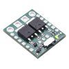
This product is a power switch implemented as a pair of P-channel MOSFETs configured as a high-side switch with reverse voltage protection and controlled by a micro slide switch. Because the main current does not go through the controlling mechanical switch, a variety of switches can be used without concern for the current they can carry. For example, a small slide or toggle switch can be mounted conveniently on a control panel with thin wires running to it, while the main power path can be shorter and with thicker wires. Pushbutton or tactile switches can also be used for momentary switching applications.
Unlike the Pololu Pushbutton Power Switches, which can lose their state when power is disconnected and reapplied, the conducting state of the MOSFET Slide Switches is determined only by the physical control switch (or a signal supplied to the “ON” pin), independent of power applied to the board. This can make them more appropriate for applications where the supplied power may be intermittent.
Warning: Do not use this switch as an emergency cutoff or similar safety disconnect in applications where failure to cut power could lead to injury or property damage.
Four versions of the MOSFET slide switches are available:
- Mini MOSFET Slide Switch LV
- Mini MOSFET Slide Switch SV
- Big MOSFET Slide Switch MP
- Big MOSFET Slide Switch HP
The two Mini MOSFET Slide Switches are smaller, lower-current versions that are useful for applications with tight size constraints or lower power requirements. Also, the the Mini LV is the only one of the four that works below 4.5 V; since it can operate down to 1.8 V, this version can be used with a single lithium cell battery.
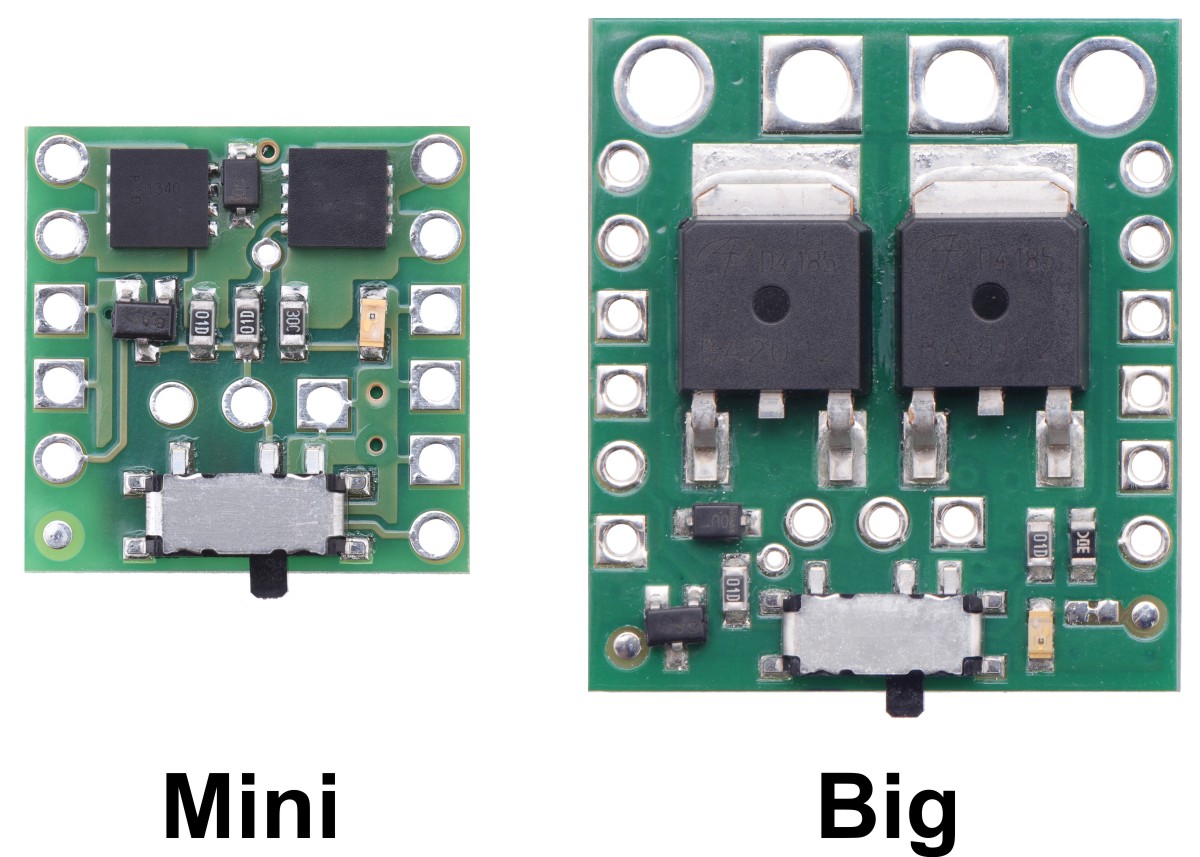 |
The pinout of the Big version is the same as the pinout of the Mini version with several additional redundant connection points for convenience, including main power connections that are compatible with 5 mm terminal blocks.
The primary functional difference between the each of the units arises from the MOSFET used, which sets the operating range and performance of the units:
 LV |  SV |  MP |  HP | |
|---|---|---|---|---|
| Absolute max voltage: | 20 V | 40 V | ||
| Recommended operating voltage: | 1.8 V to 16 V | 4.5 V to 32 V | ||
| MOSFET combined on resistance (max) | 26 mO @ 1.8 V | |||
| 16 mO @ 4.5 V | 90 mO @ 4.5 V | 40 mO @ 4.5 V | 13 mO @ 4.5 V | |
| 50 mO @ 10 V | 30 mO @ 10 V | 8.6 mO @ 10 V | ||
| Continuous current at 55°C(1) | 3.0 A | 2.0 A | 4.0 A | 6.0 A |
| Continuous current at 150°C(1) | 6.0 A | 4.3 A | 8.0 A | 16 A |
| Maximum current | 12 A | 7.2 A | 40 A | 90 A |
| Current consumption in on state(2) | ~210 µA/V | ~65 µA/V | ||
| LED color | red | green | ||
| Size | 0.6" × 0.6" × 0.1" | 0.8" × 1.0" × 0.16" | ||
| Weight | 0.6 g | 2.7 g | ||
1 At 12 V with ambient temperature of 22°C in still air.
2 On state current is dominated by indicator LED; current is approximately proportional to input voltage.
Using the MOSFET Slide Switch
|
|
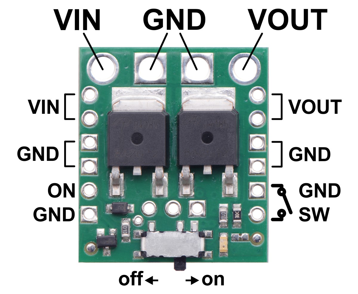
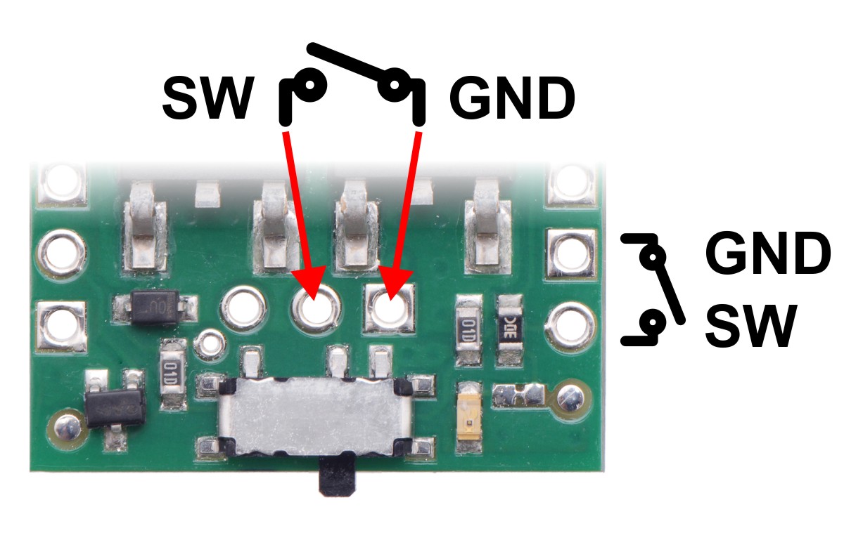
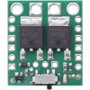
In the most basic application, power can be applied to the VIN and ground pins, with the on-board mini slide switch controlling power on the VOUT pins. To use an alternate SPST switch to control the MOSFETs, set the on-board slide switch to the off position and connect the alternate switch between ground and the switch control terminal, which is accessible both in the center of the board and along the side. The following example shows a larger slide switch soldered directly to the three through-hole pins in the center of the board:
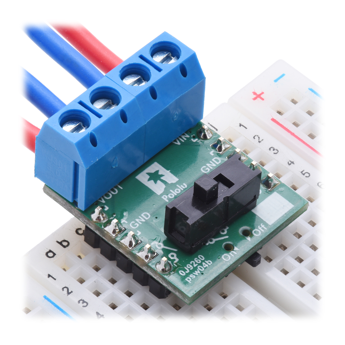 |
An example of using a different through-hole slide switch with the Big MOSFET Slide Switch. |
|---|
If the physical switch is in the “off” position, the switch state can also be controlled by a digital signal (e.g. from a microcontroller) via the “ON” control pin. Driving the “ON” pin low (or leaving it disconnected) will leave the switch off; driving the pin beyond approximately 1 V will turn the switch on. The maximum voltage for the “ON” pin is 30 V, independent of the switch voltage (VIN).
Each power node can be accessed through a large hole along the top side of the board or two smaller 0.1"-spaced holes along the sides of the board. For applications drawing more than 5 A, you should either use the large holes or both 0.1"-spaced holes for each power connection.
Included Hardware
|
|
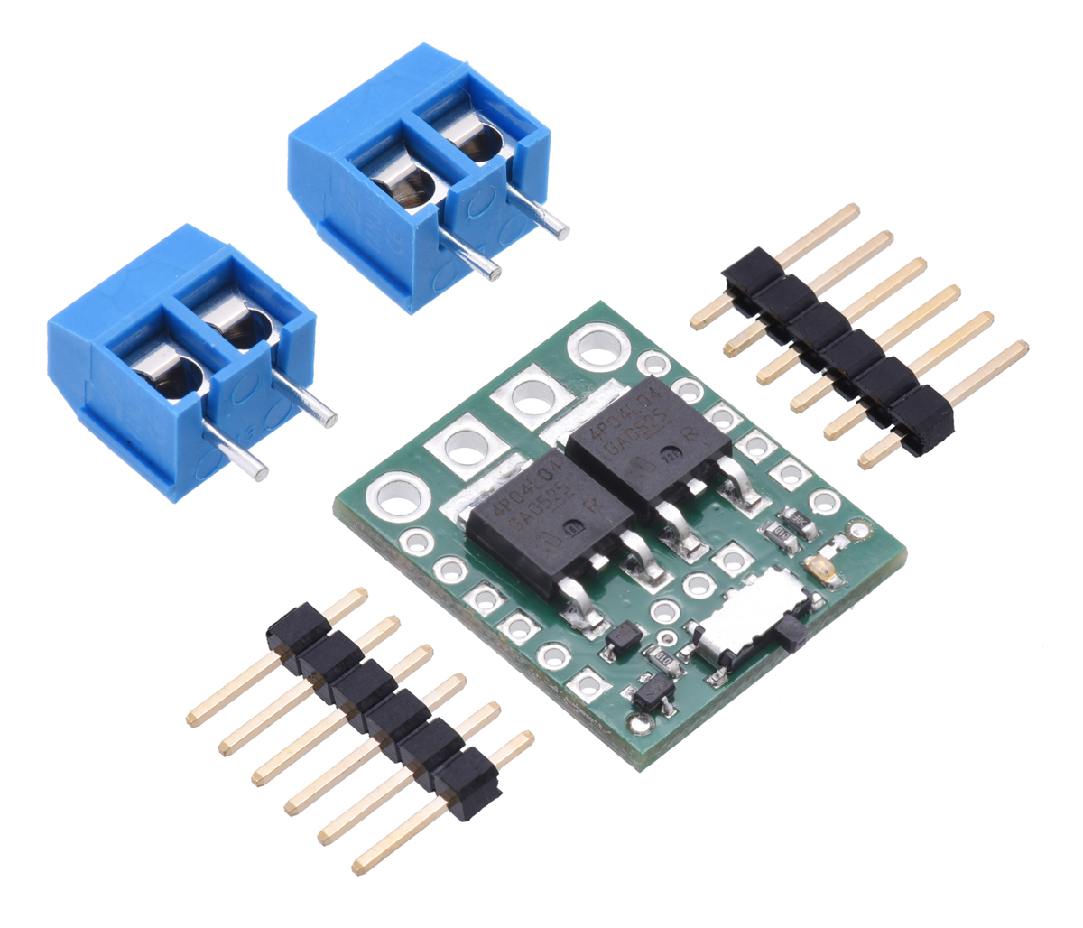
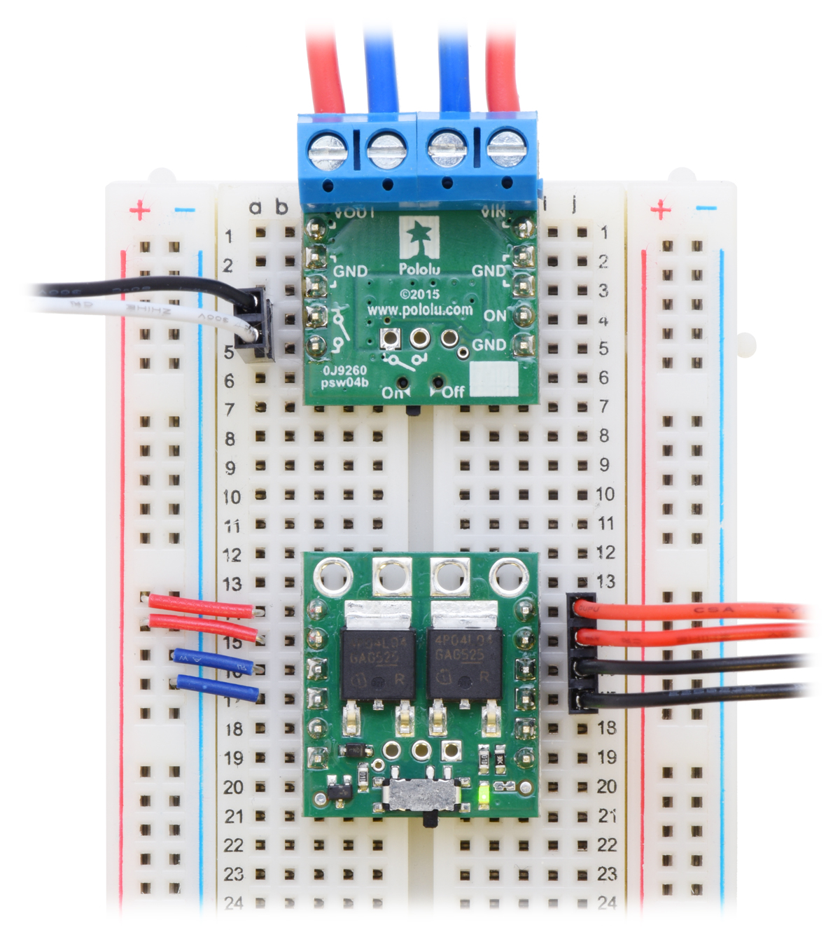
Two 6-pin straight breakaway male headers and two 2-pin 5mm terminal blocks are included with each switch, and you can choose which of these components, if any, to solder to the board. The terminal blocks work with the four large holes, and the header strips allow the switch to be used with solderless breadboards and perforated circuit boards with standard 0.1" spacing. If you want to use the terminal blocks, Pololu recommend you install them on the side of the board without components, as shown in the above breadboard picture. The terminal blocks will cover one of each of the smaller VIN and VOUT holes, so you should not solder header pins into those holes if you plan on using terminal blocks.
Note that the terminal blocks are only rated for 16 A, so for higher-power applications, thick wires should be soldered directly to the board.
 |
Thermal and power dissipation considerations
Because MOSFETs in the on state are effectively resistive, the power heating the board is proportional to the square of the current flowing through it. The comparison table near the top of this page shows typical currents that heat the MOSFETs to 55°C, where the MOSFETs start being noticeably warm but are still generally safe to touch, and currents that heat the MOSFETs to 150°C the absolute limit for the MOSFETs. With adequate cooling, or for brief periods if the MOSFETs are not hot to begin with, currents up to the listed maximums are attainable.
Transient protection
Interrupting large currents can cause voltage spikes (positive on the input side and negative on the output side) that depend on the inductance of the power connections and that can exceed the limits of the device. Appropriate measures to limit the size of these spikes include minimizing lengths of wires, placing capacitors at the power switch to smooth the spikes and absorb some of the energy, placing a schottky diode across the power output to absorb negative spikes, and placing a transient voltage suppressor (TVS) across the power input to absorb positive spikes.
Schematic diagram
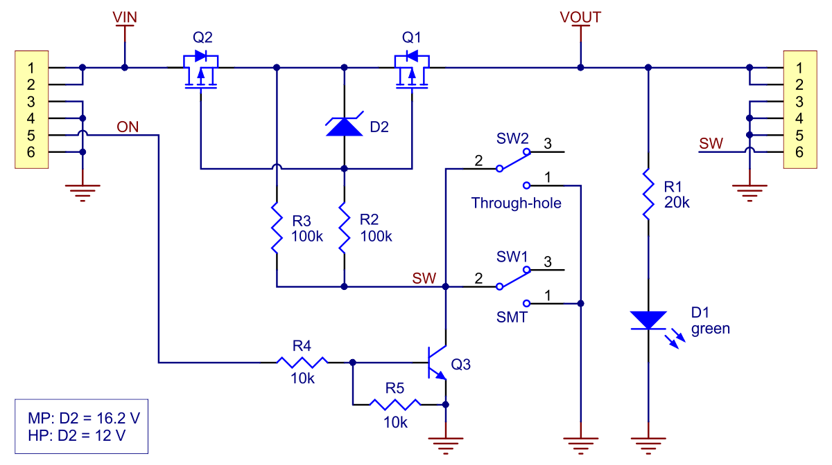 |
Schematic diagram of the Big MOSFET Slide Switch with Reverse Voltage Protection. |
|---|
This diagram is also available as a downloadable PDF (647k pdf).
People often buy this product together with:
 | Mini Pushbutton Power Switch with Reverse Voltage Protection, LV |
 | Mini MOSFET Slide Switch with Reverse Voltage Protection, LV |
 | Mini MOSFET Slide Switch with Reverse Voltage Protection, SV |
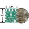
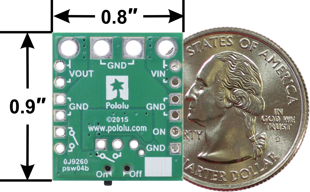
Dimensions
| Size: | 0.8" × 0.9" × 0.16"1 |
|---|---|
| Weight: | 2.6 g2 |
General specifications
| Current rating: | 16 A3 |
|---|---|
| Minimum operating voltage: | 4.5 V |
| Maximum operating voltage: | 40 V4 |
| Reverse voltage protection?: | Y |
Identifying markings
| PCB dev codes: | psw04b |
|---|---|
| Other PCB markings: | 0J9260 |
Notes:
- 1
- Without included optional connectors. This also does not include the slide switch lever, which extends past the edge of the board by approximately 0.04" (1 mm).
- 2
- Without included optional connectors.
- 3
- Continuous at 12 V, without exceeding 150°C.
- 4
- Recommended maximum is 32 V.
File downloads
-
Big MOSFET Slide Switch with Reverse Voltage Protection schematic diagram (647k pdf)
Printable schematic diagram of the Big MOSFET Slide Switch with Reverse Voltage Protection.
-
Dimension diagram of the Pololu Big MOSFET Slide Switch with Reverse Voltage Protection (389k pdf)
-
3D model of the Big MOSFET Slide Switch with Reverse Voltage Protection (3MB step)
-
Drill guide for the Big MOSFET Slide Switch with Reverse Voltage Protection (37k dxf)
This DXF drawing shows the locations of all of the board’s holes.
Exact shipping can be calculated on the view cart page (no login required).
Products that weigh more than 0.5 KG may cost more than what's shown (for example, test equipment, machines, >500mL liquids, etc).
We deliver Australia-wide with these options (depends on the final destination - you can get a quote on the view cart page):
- $3+ for Stamped Mail (typically 10+ business days, not tracked, only available on selected small items)
- $7+ for Standard Post (typically 6+ business days, tracked)
- $11+ for Express Post (typically 2+ business days, tracked)
- Pickup - Free! Only available to customers who live in the Newcastle region (must order online and only pickup after we email to notify you the order is ready). Orders placed after 2PM may not be ready until the following business day.
Non-metro addresses in WA, NT, SA & TAS can take 2+ days in addition to the above information.
Some batteries (such as LiPo) can't be shipped by Air. During checkout, Express Post and International Methods will not be an option if you have that type of battery in your shopping cart.
International Orders - the following rates are for New Zealand and will vary for other countries:
- $12+ for Pack and Track (3+ days, tracked)
- $16+ for Express International (2-5 days, tracked)
If you order lots of gear, the postage amount will increase based on the weight of your order.
Our physical address (here's a PDF which includes other key business details):
40 Aruma Place
Cardiff
NSW, 2285
Australia
Take a look at our customer service page if you have other questions such as "do we do purchase orders" (yes!) or "are prices GST inclusive" (yes they are!). We're here to help - get in touch with us to talk shop.
Have a product question? We're here to help!
 DC-DC Power Module 25WSKU: DFR0205 Brand: DFRobotThis Power Module is a small size 5A 350KHz 25V Buck DC to DC Converter.It can c ...
- Rocker Switch - Round w/ Blue LEDSKU: COM-11155 Brand: SparkfunThese panel-mounting rocker switches have built-in indicator lights to let you k ...
- Adafruit Power Relay FeatherWingSKU: ADA3191 Brand: Adafruit FeatherA Feather board without ambition is a Feather board without FeatherWings! This i ...
- Gravity: I2C SD2405 RTC ModuleSKU: DFR0469 Brand: DFRobotWe're glad to introduce a new member in Gravity family: Gravity I2C SD2405 RTC m ...


- 600 Pack of 1/4 Watt 1% Resistors (30 values, 20 of each)SKU: CE05092 Brand: Core ElectronicsThis is a pack of 600 resistors, all 1%, 1/4 Watt with markings on the paper str ...
- 120 Pack of Electrolytic Capacitors (12 types, 10 of each)SKU: CE05130 Brand: Core ElectronicsThis pack of Electrolytic Capacitors includes 12 types, 10 of each.
- Colorful Square Tactile Button Switch Assortment - 15 packSKU: ADA1010 Brand: AdafruitLittle clicky switches are standard input "buttons" on electronic projects. Thes ...
- Thru-hole 5-way Navigation switchSKU: ADA504 Brand: AdafruitThis navigation switch is an intuitive way to add 5 button's worth of interfacin ...


Guides

The Maker Revolution
Projects

The Rats Nest VCC Desktop Power Supply

Remote-Controlled Mars Rover

FlipperMate: Hands-Free Pinball

Makers love reviews as much as you do, please follow this link to review the products you have purchased.
Product Comments