As an avid space-lover, I have always admired the amazing engineering that goes into the various robotic missions we have sent out into the great unknown. Of these adventurous autonomous argonauts, the ground-based explorers such as Sojourner, Spirit and Opportunity, Curiosity and more recently Perseverance have a special character about them, no doubt because of their characteristic ‘faces’. These missions have a special place in the eyes of many people, solitary travellers in a vast, inhospitable desert millions of kilometres away.
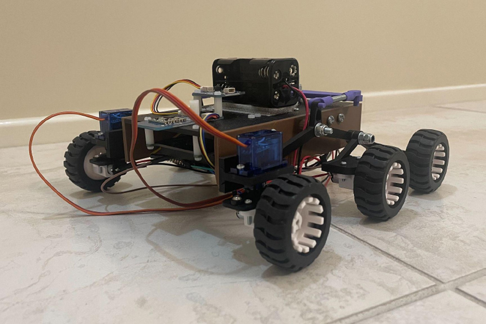
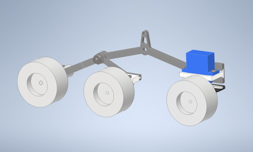
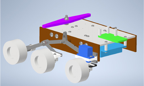
It is my admiration and avid interest in these missions that led me to create my own, albeit far simpler and smaller-scale, version. This Pico-based project sports the characteristic rocker-bogey drivetrain of the robotic Mars missions. Instead of a 20-40 minute round-trip communication, I have made use of the PiicoDev Transceiver module to communicate with the rover, and a joystick module for movement control. Four AA batteries power two steering servos and four micro metal geared DC motors with a 298:1 ratio. Using a Raspberry Pi Pico allows addition of extra modules such as an OLED on the controller for a visualisation of the direction and speed commands, as well as sensing modules such as an accelerometer on the rover itself.
Creation Process
During the design and implementation phases of this project, several issues and areas of improvement arose.
Power Management: As with all electronics projects, this rover needs a power source. However, not just any power source will do, as various components of the rover, such as the Pico, drive motors, and servos, operate at different voltages and currents.
The use of motors ruled out the possibility of using the Pico as a centralised power source due to the high and sometimes sudden current draw from each motor and servo. However, any Piicodev modules, such as the radio transceiver, could be powered by the Pico through the Qwiic connector on the LiPo platform. The metal gear motors used in the drivetrain operate nominally at 6V, whereas the servos are standard 5V servos, although their operating range is 4.8-6V. Hence, to simplify wiring, the servos and drive motors could be powered by the same source.
All that was left was powering the Pico. My original plan was to use a separate power supply, that being a 9V battery and 5V-output buck converter to safely power the Pico; an additional power supply would not only increase the complexity and wire-routing requirements of the build, but also add an additional 60g to the weight of the rover. Upon further inspection of the Makerverse motor drivers, I found they each feature a regulated 5V output, perfectly suited to power the microcontroller.
The final power solution, hence, consists of 4xAA batteries, supplying a nominal 6V to each drive and servo motor, whilst the pico picks off a regulated 5V from one of the motor drivers.
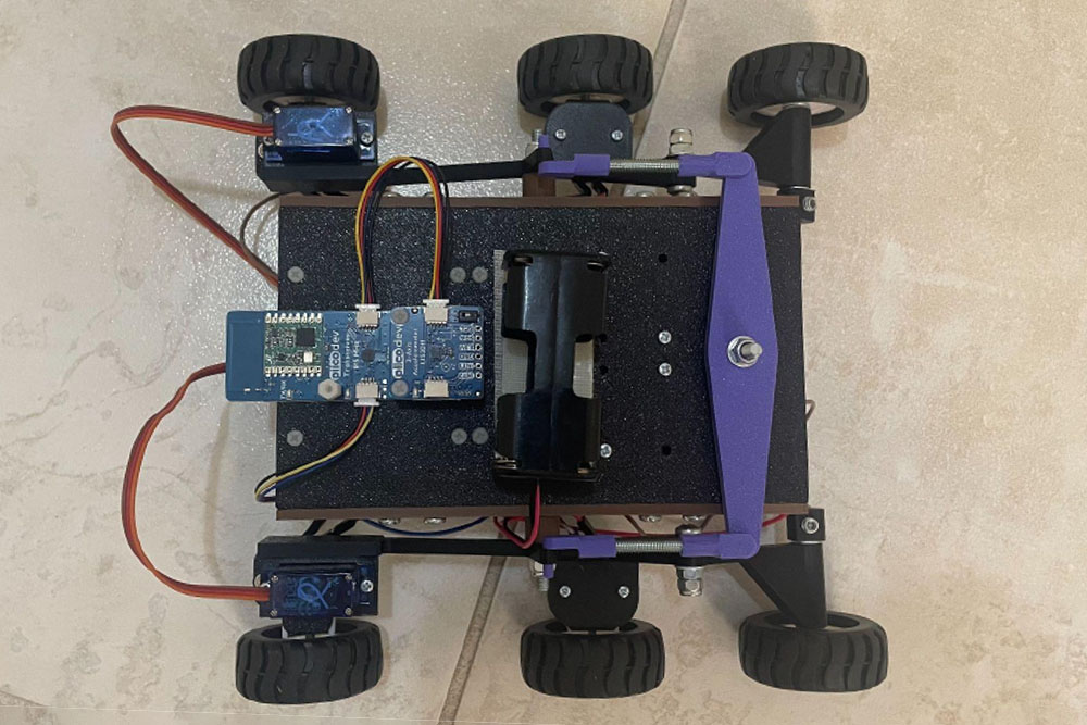
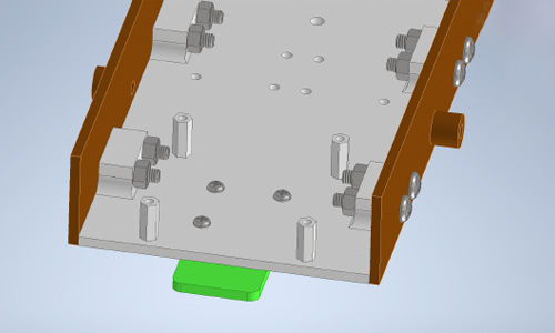
Wiring: To ensure the project was easy to build, and looked aesthetically pleasing from most angles, a protoboard and male headers were used to allow components such as the servo motors to be ‘plugged in’, whilst the wires connecting the motor drivers to the Pico and drive motors were routed underneath the standoffs.
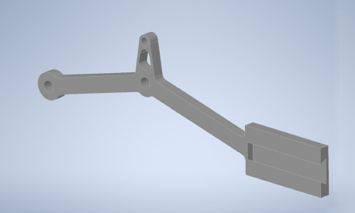
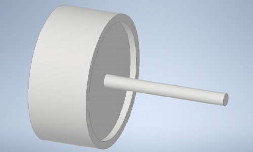
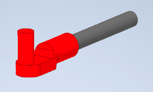
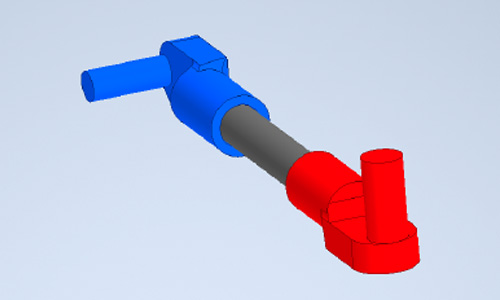
Manufacturing: For ease in prototyping and to make the rover design more accessible, I turned to 3d printing for producing the non-electronic components of the rover. A particular challenge was printing the rocker and bogey arms so they were dimensionally accurate and structurally sound.
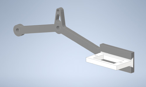
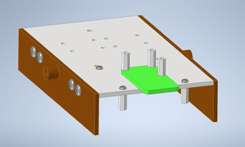
Both the rocker and bogey consist of a perpendicular protrusion with precisely sized and placed holes for mounting the servo motor and the middle drive motor, respectively. These components could either be placed upright or flat on a 3d printing build plate. Placing the rocker and bogey flat on the build plate allows for the main structure to be printed accurately and with a good surface finish, however the mounting sections will not be as strong, and the holes will not have a good finish as they are printed free-floating. Alternatively, printing the rocker and bogey so these protrusions were flat on the build plate solves the latter issue, however the rest of the structure would require supports, increasing the chances of print failure and worsening their surface finish.
The solution to this problem was printing the mounting bracket sections of the rocker and bogey separately, and using a friction-fit dovetail shape to achieve the required shape.
Future Improvements and Modifications
This design, like everything, is not without its own fair share of flaws and compromises in the name of either cost or complexity. The following are some possible future improvements and/or additions to the design to add more functionality to the rover, or improve the structure.
Solar power: For some extra realism and environmental friendliness, adding a large solar panel and rechargeable (possibly LiPo) battery would be an amazing addition, allowing the rover to better resemble its celestial counterparts. One hurdle I foresee with adding solar power and a rechargeable battery, at least a LiPo battery, would be the output voltage. As mentioned previously, the motors can run on 6V whilst the pico requires 5V. LiPo batteries have a nominal output voltage of 3.7V, so possibly a multi-cell battery or buck converter would be required.
Structural improvements: The rover design is quite wide relative to its width, which in conjunction with relatively thin and flexible rocker and bogey suspension arms, the chassis tends to sag slightly. Increasing the angle of the rocker and bogey will raise the rover more off the ground, as well as increased width of the connecting arms would improve the rigidity of the drivetrain. Additionally, some ribs and built-in struts on the rocker and bogey arms will reduce the bending deflection when under load. The width of the chassis itself could be narrowed slightly, however the electronic components and wires do fit nicely on the underside as-is.
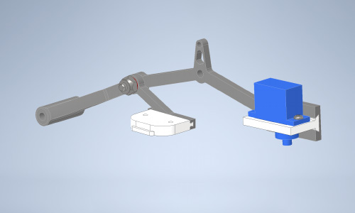
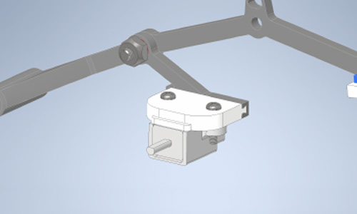
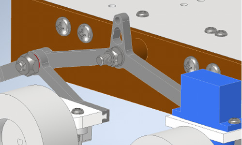
Another structural improvement is to the motor attachment bracket for the front servo motors. When assembled, it is quite difficult for a screwdriver to access the screw heads and securely fit the pieces together. Alternatively, increasing the distance between the driver motor and servo horn attachment, possibly by using two brackets instead of one, could improve the assembly process. Specifically, rather than using one bracket to attach to the servo horn and the drive motor, one plate/bracket could be made that attaches to the servo, and then a second is created to attach the drive motor. The bracket of the servo horn would feature raised hollow cylinders for screws, which would attach the drive motor bracket to the servo horn bracket.
Steering: For simplicity and to reduce cost, this rover design features a single pair of servos mounted at the front for steering. In reality, six-wheeled rovers feature a second pair of steered wheels at the rear. Adapting the bogey to allow for another servo and/or drive motor would not only increase the rover's top straight line speed, but also decrease the turning circle and eliminate any skidding from the rear wheels when steering.
Sensors: Through the use of a Raspberry Pi Pico, additional PiicoDev (or other) sensors could be attached in a modular fashion to, say, measure magnetic heading, acceleration, or equip distance sensors to allow for automatic or semi-automatic pathfinding.
Bill of Materials
| Description | Quantity | Price (AUD$) | Subtotal |
|---|---|---|---|
| Raspberry Pi Pico 2 (or equivalent microcontroller) | 2 | 8.70 | 17.40 |
| PiicoDev LiPo Expansion Module | 2 | 5.40 | 10.80 |
| PiicoDev Transceiver Module | 2 | 20.05 | 40.10 |
| Makerverse 2 Channel Motor Driver | 2 | 7.10 | 14.20 |
| FS90MG Micro Servo | 2 | 7.40 | 14.80 |
| Micro Metal Geared DC motor (6V 50RPM) | 4 | 13.50 | 54.00 |
| Pololu Micro Metal Gearmotor Bracket Pair Extended | 2 | 8.35 | 16.70 |
| Wheel Pair 42x19mm | 3 | 3.95 | 11.85 |
| PiicoDev OLED Module | 1 | 11.95 | 11.95 |
| Joystick Module | 1 | 9.25 | 9.25 |
| AA Battery Holder (4 x AA) | 1 | 6.95 | 6.95 |
| Male to Female Jumper Wires | 1 | 7.50 | 7.50 |
| Male Pin Headers | 1 | 0.35 | 0.35 |
| Protoboard | 1 | 1.75 | 1.75 |
| Piicodev 3 Module Platform | 2 | 4.80 | 9.60 |
| Stahl 383 Assorted Fasteners Kit | 1 | 5.35 | 5.35 |
| M4 Nylock Bolts | 1 | 4.95 | 4.95 |
| M4 Threaded Rod (approximately 70 mm total length) | 1 | ? | ? |
| M4 Steel Rod (approximately 100 mm total length) |
1 | ? | ? |
| M5 Grub Screws Socket Head 5 Pack (Bunnings) | 1 | 4.15 | 4.15 |
| PiicoDev Cable 100mm | 3 | 0.85 | 2.55 |
| Total | 244.20 | ||
Build Process:
Rover:
1. Take the right rocker piece
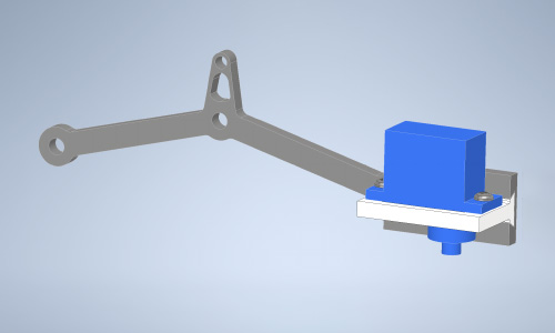
2. Slot in a servo holder into the in-built dovetail
3. Screw the servo to the bracket using M2.5 x 6 screws. Ensure the servo is in its neutral head position
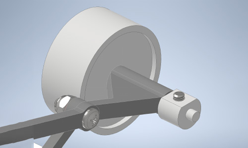
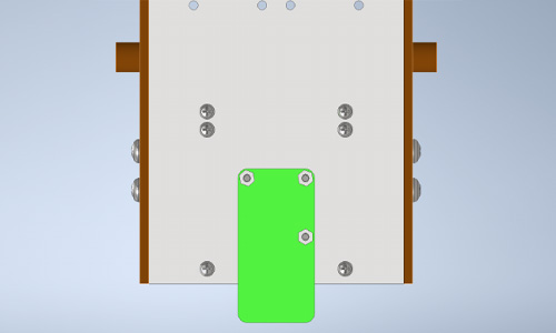
4. Slot a M4 screw through the rocker and right bogey with a washer (shown in red)
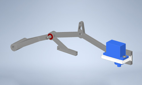
5. Fasten the bogey to the rocker with an M4 Nylock nut
6. Slot in a motor holder to the bogey dovetail
7. Screw in the motor bracket and motor to the bogey
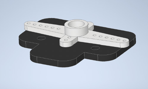
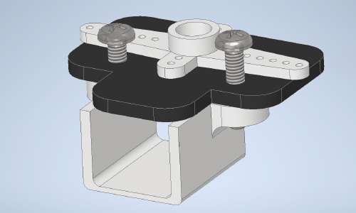
8. Take a servo attachment plate with slits for attaching it to the servo horn
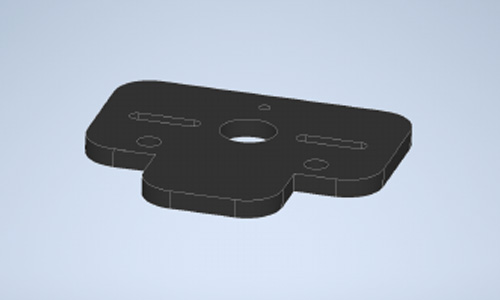
9. Screw the two-pronged servo horn to the attachment plate
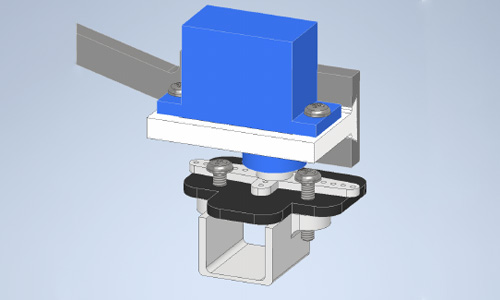
10. Loosely screw the motor bracket to the attachment plate, leaving room for screwdriver access to the plate’s central hole for fastening the horn to the servo head
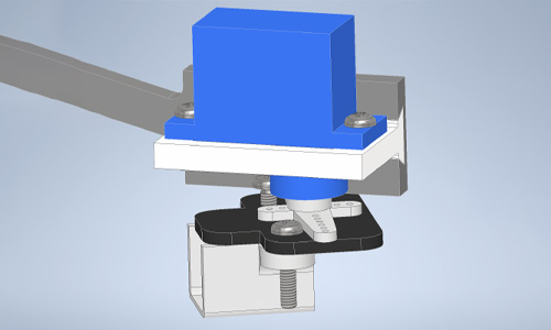
11. Using a fine screwdriver, fit the servo horn to the servo and screw in the horn to the servo head.
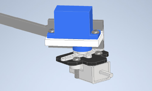
12. Rotate the servo manually to the two extremes to fully screw in the motor and motor bracket with a fine screwdriver
13. Repeat the previous step for the final motor bracket screw
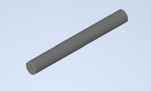
14. Press fit a wheel to a 50 mm length of M4 steel rod. File down the end manually to create a D profile.
15. Slot the wheel and axle into the rear of the bogey and lock it in place using a collar and M5 set screw.
16. Press fit the remaining wheels onto the motor shafts. Repeat for the left hand side.
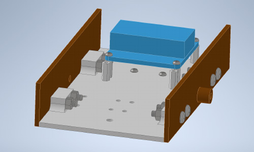
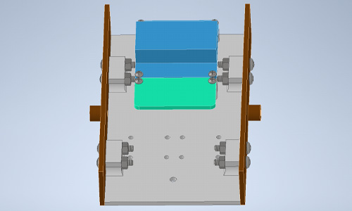
17. Take the rover base plate
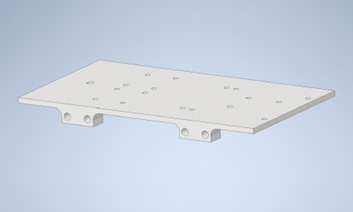
18. Place the side panels either side, lining up the four mounting holes
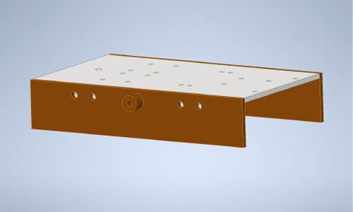
19. Fasten the side panels to the base plate using M4 x 20 screws and M4 nuts
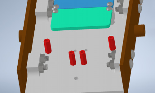
20. Attach four nylon M2.5 hexagonal standoffs to the underside of the base plate
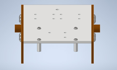
21. Attach the PiicoDev Transceiver module to the top of the base plate using the three inner mounting holes on the base plate
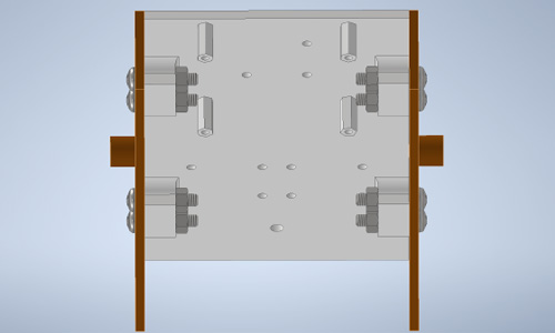
22. Screw the PiicoDev LiPo platform to the four hexagonal standoffs on the underside of the base plate
23. Attach two more hexagonal standoffs adjacent to the LiPo platform on the underside of the base plate
24. Screw the protoboard to the two standoffs adjacent to the Lipo platform
25. Attach four more hexagonal standoffs in a diagonal pattern on the underside of the base plate
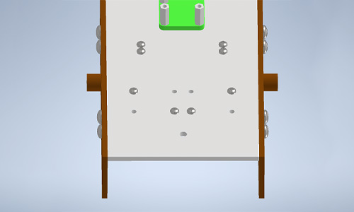
26. Screw the two Makerverse motor drivers to the diagonally-placed hexagonal standoffs
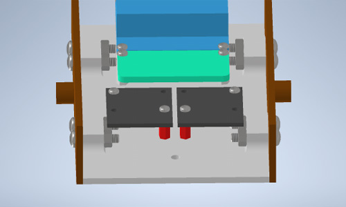
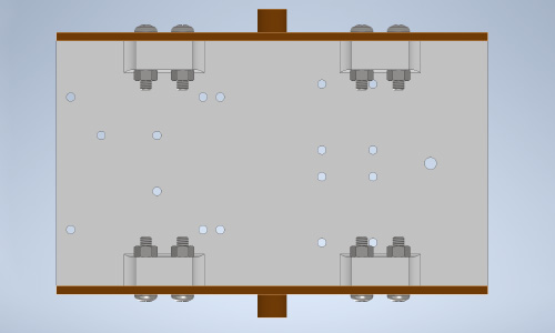
27. Place two M4x20 screws on the inside of each side plate, threads sticking outside the chassis.
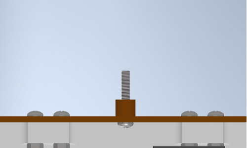
28. Place an M4x20 screw through the single hole at the rear of the chassis, threads sticking out above the base plate, and fasten it in place with a nut and two washers on top of the nut for spacing.
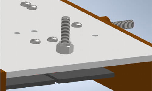
27. Place two M4x20 screws on the inside of each side plate, threads sticking outside the chassis.
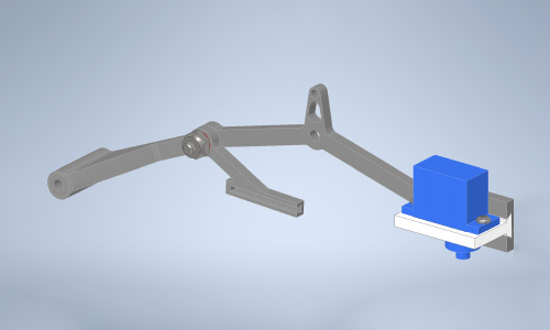
30. Attach each rocker and bogey assembly to the bolt of each side plate.
31. Fasten each rocker and bogey assembly with an M4 nylock nut and washer
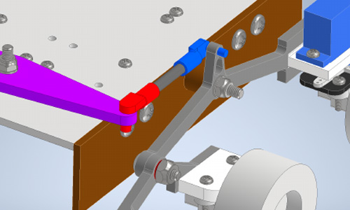
32. Take a 35 mm length of M4 threaded steel rod
33. Thread the hook with a larger pin diameter onto the threaded rod. Do not thread the hook all the way
34. Thread the hook with the smaller pin diameter onto the threaded rod, leaving the pin perpendicular to the larger pin. Do not thread the hook on the thread the entire way.
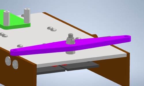
35. Press-fit the larger pin into the outer hole of the suspension arm and press-fit the smaller pin into the respective hole in each rocker assembly. Thread or unthread the smaller / larger pin hook to ensure each side is level.
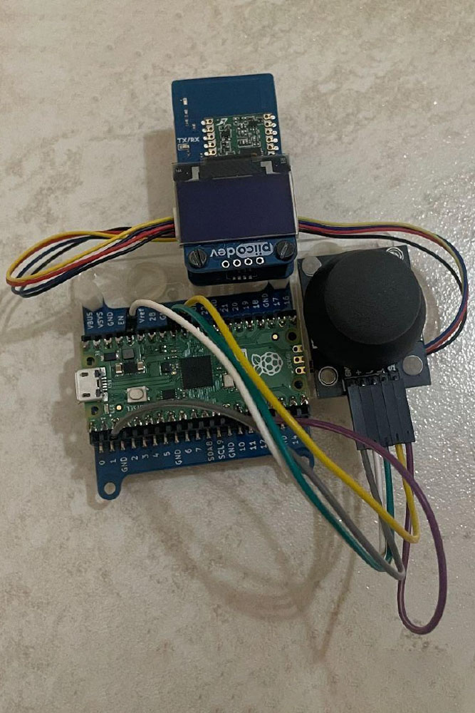
Controller:
Assemble a Pico 2, Lipo platform, joystick module, and PiicoDev OLED and Transceiver module on one 3-module mounting platform as shown in the image below:
Joystick Circuit Diagram
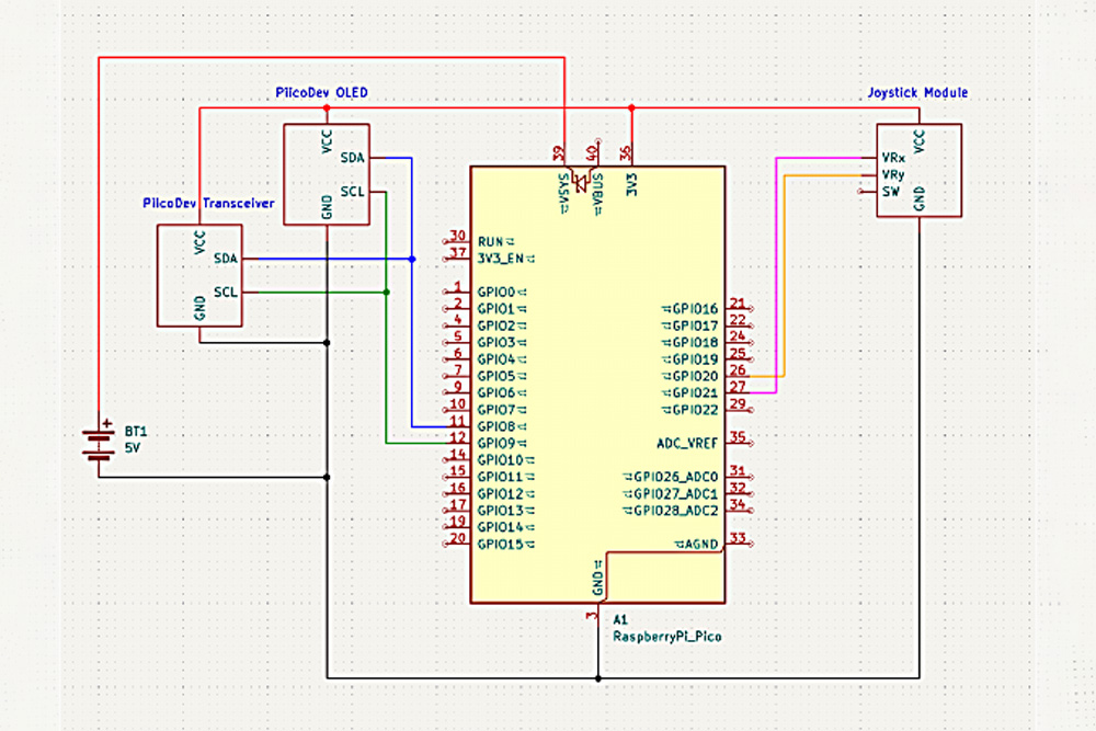
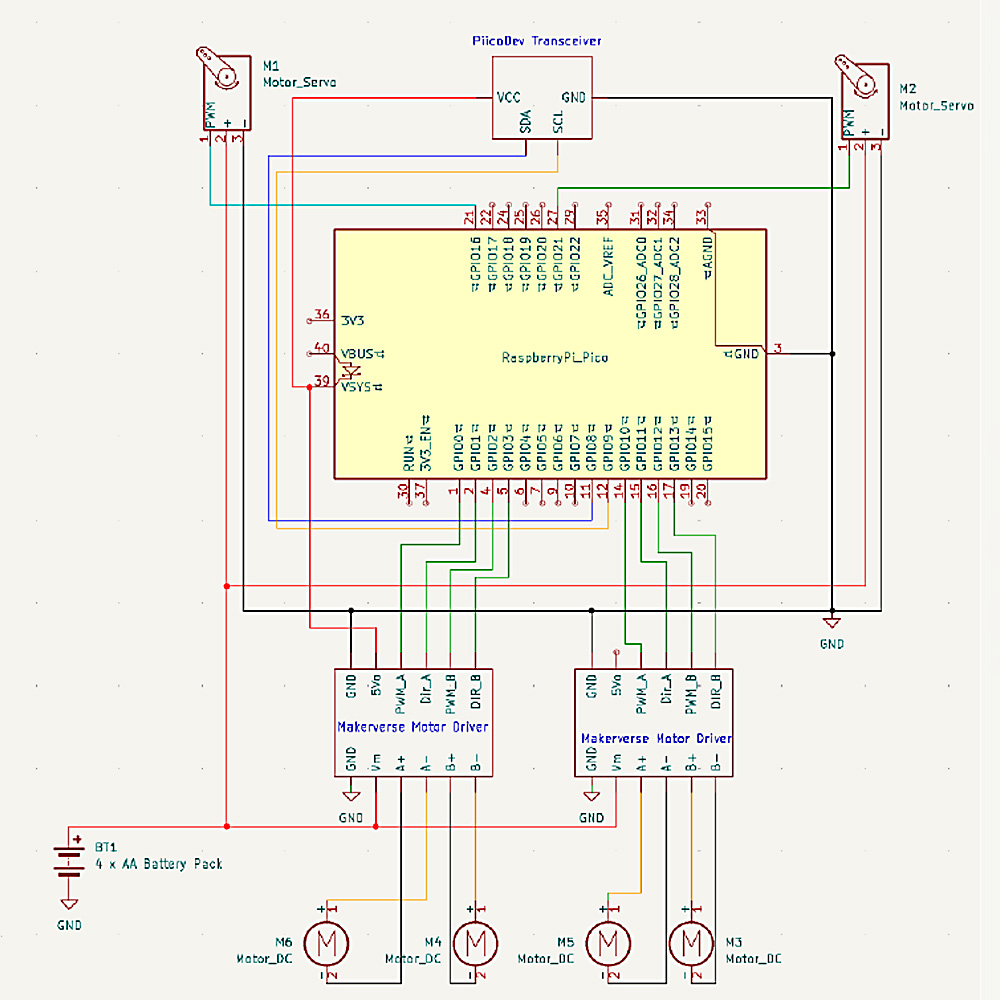
Rover Circuit Diagram
Controller Code
from machine import Pin, ADC
from PiicoDev_Unified import sleep_ms
from PiicoDev_Transceiver import PiicoDev_Transceiver
from PiicoDev_SSD1306 import create_PiicoDev_SSD1306, WIDTH, HEIGHT
from math import sin, cos, radians

oled = create_PiicoDev_SSD1306()

oled.rotate(0)

# Start sequence
oled.fill(0)
oled.text("Starting...", 0, 0)
oled.show()
sleep_ms(300)

oled.fill(0)
oled.rect(24,14,80,36,1)
oled.circ(45,28,4,0)
oled.circ(80,27,7,0)
oled.rect(50,40,10,5,1)
oled.line(88,14,88,8,1)
oled.circ(88,4,4,0)
oled.text("RC Rover",0,0)
oled.show()
sleep_ms(2000)

# Pins for Joystick Module
xAxis = ADC(Pin(27))
yAxis = ADC(Pin(26))

button = Pin(17, Pin.IN, Pin.PULL_UP)

radio = PiicoDev_Transceiver()

centreX = int(WIDTH/2)
centreY = int(HEIGHT/2)

# Custom map function like in Arduino for converting the joystick pot readings to a specified range
def map(input, in_min, in_max, out_min, out_max):
    return (input - in_min) * (out_max - out_min) / (in_max - in_min) + out_min

# This function is from the magnetometer demo guide from Core, it draws the artwork onto the OLED display.
# It was exactly what I wanted in terms of visualising what command the controller was sending.
# It takes an angle and draws a line at that angle from the centre of the display - along with some other nice stuff.
def drawCompass(heading, vel):
    rads = radians(heading + 180) # convert angle to radians and offset by 180 degrees (to account for y increasing down the display)
    length = map(vel, -95, 95, -25, 25) # compass needle length (in pixels) from centre proportional to speed

    if length < 0:
        rads = radians(180 - heading)

    # Convert polar coordinates (length, angle) to cartesian coordinates (x,y) for plotting on display. Offset the coordinates by half the screen width/height to draw from the centre - rather than the top-left of the display.
    x = int( length * sin(rads) + WIDTH/2 )
    y = int( length * cos(rads) + HEIGHT/2 )

    # Plot the compass on the display
    oled.fill(0)
    oled.line(centreX, centreY, x, y, 1) # draw the compass needle
    oled.circ(x,y,4)                  # put a forward-indicator on the end
    oled.text(str(heading),100,57)      # show the heading in the bottom-right corner
    oled.text(str(vel),0,57)          # show the speed in the bottom left corner
    oled.show()

while True:
    oled.fill(0)

    # Read Joystick potentiometer values
    xValue = xAxis.read_u16()
    yValue = yAxis.read_u16()
    buttonValue = button.value()

    # Getting an angle and speed based on how far forward / backward and left / right the stick is, respectively
    # 65 degrees to 115 degrees was chosen since there are only 2 steering wheels and the chassis is relatively long
    Angle = map(yValue, 0, 65535, 65, 115)
    Speed = int(map(xValue, 0, 65535, -95,95))

    # Buffer zone for noise
    if -10 <= Speed and Speed <= 10:
        Speed = 0

    Heading = 90 - round(Angle)
    drawCompass(Heading, Speed)

    radio.send(("Speed", Speed))
    sleep_ms(25)
    radio.send(("Angle", int(Angle)))
    sleep_ms(25)
Rover Code
from PiicoDev_Transceiver import PiicoDev_Transceiver
from Makerverse_Motor_2ch import motor
from servo import Servo
from PiicoDev_Unified import sleep_ms

radio = PiicoDev_Transceiver()

left_servo = Servo(pin_id = 27)
right_servo = Servo(pin_id = 21)

mleft1 = motor(pwmPin = 12, dirPin = 13)
mleft2 = motor(pwmPin = 10, dirPin = 11)
mright1 = motor(pwmPin = 2, dirPin = 3)
mright2 = motor(pwmPin = 0, dirPin = 1)

# # Grouping motors
left_side = [mleft1, mleft2]
right_side = [mright1, mright2]
steering = [left_servo, right_servo]

old_angle = 90
new_angle = 0
speed = 0

# Driving function
def drive(left_speed, right_speed):
    if abs(left_speed) <= 15:
        for left in left_side:
            left.stop()
    else:
        for left in left_side:
            left.speed(left_speed)

    if abs(right_speed) <= 15:
        for right in right_side:
            right.stop()
    else:
        for left in left_side:
            left.speed(left_speed)

        for right in right_side:
            right.speed(right_speed)

while True:
    # Receiving and sorting data
    if radio.receive():
        message = radio.message
        if message[0] == "Speed":
            speed = message[1]
        if message[0] == "Angle":
            new_angle = message[1] - 3

    # Setting Steering angle

    new_angle = max(65, min(115, int(new_angle))) # Trying to avoid incorrect overshoots from servos

    # Gradually moving servos according to direction, adding +step since last value is excluded in range
    if abs(new_angle - old_angle) >= 2:
        for servo in steering:
            servo.write(new_angle)
    else:
        for servo in steering:
            servo.write(old_angle)

    old_angle = new_angle

    # Driving Block:
    # Due to the width of the rover, the wheel speeds have to be changed to avoid slipping and allow turning
    inside_speed = int(0.60*speed)
    outside_speed = int(0.90*speed)

    if 65 <= new_angle and new_angle <= 80:
        drive(inside_speed, outside_speed)
    elif 100 <= new_angle and new_angle <= 115:
        drive(outside_speed, inside_speed)
    else:
        drive(speed, speed)

    sleep_ms(25)
