


Pololu 3.3V, 2.6A Step-Down Voltage Regulator D24V22F3
Available with a lead time
Expect dispatch between Jul 27 and Jul 30
Quantity Discounts:
- 10+ $27.71 (exc GST)
- 25+ $26.85 (exc GST)
 |
The D24V22Fx family of step-down voltage regulators generates lower output voltages from input voltages as high as 36 V. They are synchronous switching regulators (also called switched-mode power supplies (SMPS) or DC-to-DC converters) with typical efficiencies of 85% to 95%, which is much more efficient than linear voltage regulators, especially when the difference between the input and output voltage is large. These regulators can typically support continuous output currents between 1.4 A and 2.6 A, though the actual available output current is a function of the input voltage and efficiency (see the Typical efficiency and Maximum continuous output current sections below). In general, the available output current is a little higher for the lower-voltage versions than it is for the higher-voltage versions, and it decreases as the input voltage increases.
These regulators have a typical quiescent (no load) current draw of around 1 mA, and an enable pin can be used to put the boards in a low-power state that reduces the quiescent current to approximately 5 µA to 10 µA per volt on VIN.
The modules have built-in reverse-voltage protection, short-circuit protection, a thermal shutdown feature that helps prevent damage from overheating, and a soft-start feature that reduces inrush current.
Several different fixed output voltages are available:
- D24V22F3: Fixed 3.3V output
- D24V22F5: Fixed 5V output
- D24V22F6: Fixed 6V output
- D24V22F7: Fixed 7.5V output
- D24V22F9: Fixed 9V output
- D24V22F12: Fixed 12V output
The different voltage versions of this regulator all look very similar, so you should consider adding your own distinguishing marks or labels if you will be working simultaneously with multiple versions. This product page applies to all versions of the D24V22Fx family.
The D24V22Fx family is intended to replace Pololu's older D24V25Fx family of step-down voltage regulators. The two designs have the same size and similar current capabilities and input voltage ranges, but they do not have the same pinout and are based on different internal circuits, so there are fundamental differences in operation. In particular, these newer D24V22Fx regulators have much lower dropout voltages and provide a “power good” signal, and the newer design allows for higher output voltages (e.g. 12 V).
For higher-power alternatives, please consider Pololu's D36V28Fx family of step down regulators that can handle current between 2 A and 4 A and take input voltages up to 50 V.
Pololu manufacture these boards in-house at Pololu's Las Vegas facility, which gives Pololu the flexibility to make these regulators with customized components to better meet the needs of your project. For example, if you have an application where the input voltage will always be below 20 V and efficiency is very important, Pololu can make these regulators a bit more efficient at high loads by replacing the 40V reverse voltage protection MOSFET with a 20V one. Pololu can also customize the output voltage. If you are interested in customization, please contact us.
Features
- Input voltage:
- 4 V to 36 V for the version that outputs 3.3 V
- [output voltage + dropout voltage] to 36 V for output voltages of 5 V and higher (see the dropout voltage section for details)
- Fixed 3.3 V, 5 V, 6 V, 7.5 V, 9 V, or 12 V output (depending on regulator version) with 4% accuracy
- Typical maximum continuous output currents between 1.4 A abd 2.6 A (see the maximum continuous output current graph below)
- Typical efficiency of 85% to 95%, depending on input voltage, output voltage, and load (see the efficiency graph below)
- Switching frequency: ~400 kHz
- Integrated reverse-voltage protection, over-current and short-circuit protection, over-temperature shutoff, and soft-start
- 1 mA typical no-load quiescent current; this can be reduced to approximately 5 µA to 10 µA per volt on VIN by disabling the board (see the quiescent current graph below)
- “Power good” output indicates when the regulator cannot adequately maintain the output voltage
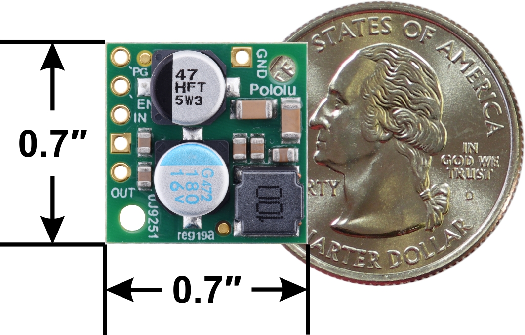
- Compact size: 0.7" × 0.7" × 0.31" (17.8 mm × 17.8 mm × 8 mm)
- Two 0.086" mounting holes for #2 or M2 screws
Using the regulator
Connections
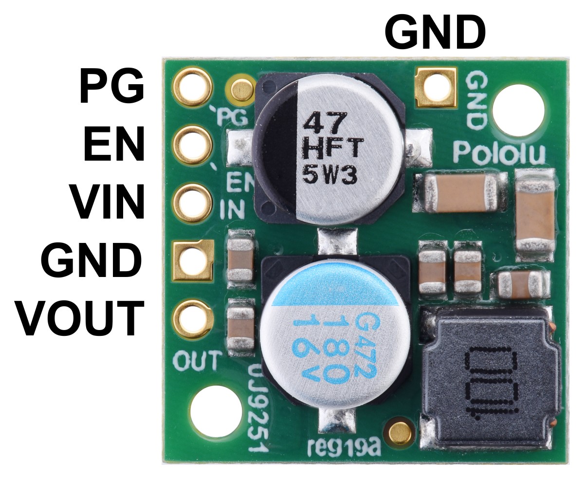
These buck regulators have five main connection points for five different electrical nodes: power good (PG), enable (EN), input voltage (VIN), ground (GND), and output voltage (VOUT). The board also features a second ground connection point off the main row of connections that might be convenient for applications where you are soldering wires directly to the board rather than using it in a breadboard.
 |
The input voltage, VIN, powers the regulator. Voltages between 4 V and 36 V can be applied to VIN, but for versions of the regulator that have an output voltage higher than 4 V, the effective lower limit of VIN is VOUT plus the regulator’s dropout voltage, which varies approximately linearly with the load (see below for a graph of dropout voltages as a function of the load).
The output voltage, VOUT, is fixed and depends on the regulator version: the D24V22F3 version outputs 3.3 V, the D24V22F5 version outputs 5 V, the D24V22F6 version outputs 6 V, the D24V22F7 version outputs 7.5 V, the D24V22F9 version outputs 9 V, and the D24V22F12 version outputs 12 V.
The regulator is enabled by default: a 270 kO pull-up resistor on the board connects the EN pin to reverse-protected VIN. The EN pin can be driven low (under 1 V) to put the board into a low-power state. The quiescent current draw in this sleep mode is dominated by the current in the pull-up resistor from EN to VIN and by the reverse-voltage protection circuit, which altogether will draw between 5 µA and 10 µA per volt on VIN when EN is held low. If you do not need this feature, you should leave the EN pin disconnected.
The “power good” indicator, PG, is an open-drain output that goes low when the regulator’s output voltage falls below around 85% of the nominal voltage and becomes high-impedance when the output voltage rises above around 90%. An external pull-up resistor is required to use this pin.
|
|


The five main connection points are labeled on the top of the PCB and are arranged with a 0.1" spacing for compatibility with solderless breadboards, connectors, and other prototyping arrangements that use a 0.1" grid. Either the included 5×1 straight male header strip or the 5×1 right angle male header strip can be soldered into these holes. For the most compact installation, you can solder wires directly to the board.
 |
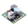
Pololu Step-Down Voltage Regulator D24V22Fx, side view. |
|---|
The board has two 0.086" (2.18 mm) diameter mounting holes intended for #2 or M2 screws. The mounting holes are at opposite corners of the board and are separated by 0.52" (13.21 mm) both horizontally and vertically. For all the board dimensions, see the dimension diagram (204k pdf).
Details for item #2857
Typical efficiency
The efficiency of a voltage regulator, defined as (Power out)/(Power in), is an important measure of its performance, especially when battery life or heat are concerns. This family of switching regulators typically has an efficiency of 85% to 95%, though the actual efficiency in a given system depends on input voltage, output voltage, and output current. See the efficiency graph below for more information.
 |
Typical dropout voltage
The dropout voltage of a step-down regulator is the minimum amount by which the input voltage must exceed the regulator’s target output voltage in order to ensure the target output can be achieved. For example, if a 5 V regulator has a 1 V dropout voltage, the input must be at least 6 V to ensure the output is the full 5 V. Generally speaking, the dropout voltage increases as the output current increases. Since this family of regulators require an input voltage of at least 4 V, dropout voltage is not a consideration for this 3.3 V version.
Maximum continuous output current
The maximum achievable output current of these regulators varies with the input voltage but also depends on other factors, including the ambient temperature, air flow, and heat sinking. The graph below shows maximum output currents that these regulators can deliver continuously at room temperature in still air and without additional heat sinking.
 |
During normal operation, this product can get hot enough to burn you. Take care when handling this product or other components connected to it.
Quiescent current
The quiescent current is the current the regulator uses just to power itself, and the graph below shows this for the different regulator versions as a function of the input voltage. The module’s EN input can be driven low to put the board into a low-power state where it typically draws between 5 µA and 10 µA per volt on VIN.
 |
People often buy this product together with:
 | Pololu 5V, 2.5A Step-Down Voltage Regulator D24V22F5 |
 | Pololu 12V, 2.2A Step-Down Voltage Regulator D24V22F12 |
 | Pololu 5V, 5A Step-Down Voltage Regulator D24V50F5 |
Dimensions
| Size: | 0.7" × 0.7" × 0.31"1 |
|---|---|
| Weight: | 2.3 g1 |
General specifications
| Minimum operating voltage: | 4 V |
|---|---|
| Maximum operating voltage: | 36 V |
| Continuous output current: | 2.3 A2 |
| Output voltage: | 3.3 V |
| Reverse voltage protection?: | Y |
| Maximum quiescent current: | 1 mA3 |
Identifying markings
| PCB dev codes: | reg19a |
|---|---|
| Other PCB markings: | 0J9251 |
Notes:
- 1
- Without included optional headers.
- 2
- Typical continuous output current at 24 V in. Actual achievable continuous output current is a function of input voltage and is limited by thermal dissipation. See the output current graph under the description tab for more information.
- 3
- Quiescent current is typically under 1 mA for most of the operating range. The ENABLE pin can be used to reduce the quiescent current to less than 10 µA per volt on VIN.
File downloads
Exact shipping can be calculated on the view cart page (no login required).
Products that weigh more than 0.5 KG may cost more than what's shown (for example, test equipment, machines, >500mL liquids, etc).
We deliver Australia-wide with these options (depends on the final destination - you can get a quote on the view cart page):
- $3+ for Stamped Mail (typically 10+ business days, not tracked, only available on selected small items)
- $7+ for Standard Post (typically 6+ business days, tracked)
- $11+ for Express Post (typically 2+ business days, tracked)
- Pickup - Free! Only available to customers who live in the Newcastle region (must order online and only pickup after we email to notify you the order is ready). Orders placed after 2PM may not be ready until the following business day.
Non-metro addresses in WA, NT, SA & TAS can take 2+ days in addition to the above information.
Some batteries (such as LiPo) can't be shipped by Air. During checkout, Express Post and International Methods will not be an option if you have that type of battery in your shopping cart.
International Orders - the following rates are for New Zealand and will vary for other countries:
- $12+ for Pack and Track (3+ days, tracked)
- $16+ for Express International (2-5 days, tracked)
If you order lots of gear, the postage amount will increase based on the weight of your order.
Our physical address (here's a PDF which includes other key business details):
40 Aruma Place
Cardiff
NSW, 2285
Australia
Take a look at our customer service page if you have other questions such as "do we do purchase orders" (yes!) or "are prices GST inclusive" (yes they are!). We're here to help - get in touch with us to talk shop.
Have a product question? We're here to help!
 Signal Diode (1N4148)SKU: CE05255 Brand: Core Electronics0.2A Forward Current, 1V Forward Voltage, Fast Switching Type.
- Voltage Regulator 5V (7805)SKU: CE05291 Brand: Core Electronics
An absolute staple! The ubiquitous L7805 voltage regulator, a three-terminal ...
- Low Profile Crystal Oscillator - 10 MhzSKU: CE05292 Brand: Core ElectronicsIdeal for precise MCU timing.
- Dual Digital Display DC Voltmeter & Ammeter 0-100V 0-100ASKU: CE05132 Brand: Core ElectronicsAn all in one solution for monitoring voltage and current.


- Heat Sink Thermal Tape - 3M 8810 - 80mm x 80mmSKU: ADA1468 Brand: AdafruitGet that heat sink stuck on good and strong with 3M's thermal tape. Specifically ...
- Raspberry Pi Model B - GPIO Shrouded Header (2x20)SKU: PRT-13054 Brand: SparkfunThis 2x20 shrouded header has the same number and spacing of pins as the Raspber ...
- Raspberry Pi B - GPIO Ribbon Cable (40-pin, 150mm)SKU: CAB-13028 Brand: SparkfunThis 2x20 flat ribbon-cable fits the GPIO headers on the Raspberry Pi B+ so you ...
- LED Holder - 5mm (Chrome Finish)SKU: COM-11147 Brand: SparkfunThese plastic LED holders have a slick chrome finish and make it possible to pan ...


Videos
View AllGuides

PiicoDev Magnetometer- Getting Started Guide

How to Drive High Power LEDs – 3W Aluminum Backed Star LEDs

The Maker Revolution

How to Use DC Regulators/Converters
Projects

The Rats Nest VCC Desktop Power Supply

Wireless QI Phone Charger Powered by Raspberry Pi

mmPi-Pico HAT

Makers love reviews as much as you do, please follow this link to review the products you have purchased.
Product Comments