High power LEDs (Light Emitting Diodes) have different requirements that need to be met when compared to regular LEDs. Current regulation using only resistors is impractical so it is necessary to use a switched-mode voltage and current regulator. Also, they generate significantly more heat which must be drawn away from the LED to prevent overheating damage. This guide will provide all the knowledge, tools and process to power whatever High Powered LEDs you happen to come across.
High power LEDs are almost always Surface Mounted components. Through-hole designs don’t provide enough heat conduction. Warm Red 3 Watt Aluminum backed PCB LEDs are what will be used here but worth noting there are other power levels and types (fully addressable LEDs and kinds of colours) that will suit whatever set-up you want. All single colour LEDs will work with a system like the one set up here
We will figure out what wires to use (selecting the right gauge), choose good heat sinks to pull enough heat away, and dive into voltage/current requirements using the Datasheets so we can select the correct electrical componentry. LEDs are incredible pieces of modern technology, the real unsung heroes in our electronics world, but they do need to be utilised correctly to take advantage of not only their incredible brightness but their long lifespan as well. The contents of this guide can be seen below.
· What You Need
· What are LEDs
· LED Current and Voltage Requirements
· Choosing the Buck (Step-Down) or Boost (Step-Up) Converter as the LED Driver
· Determine the Wire Gauge
· Schematics and Hardware Set-Up for One High Power LED
· Demonstration of Single LED Node
· Schematics and Hardware Set-Up for Four High Power LEDs in Series with a Switch
· Demonstration of Four LED Nodes in Series
· Where to Now - Other Colours, Dimming and 3D Printed Cases for Toggle Switch and LED Driver
LED is an electrical component that emits light when electricity flows through in one direction, from the Anode (positive side) to the Cathode (negative side). LED is an acronym standing for ‘Light Emitting Diode’. Basically, LEDs are like tiny light bulbs, they just require a lot less power to light up and are much more efficient in producing high light outputs. This will be focused on single colour non-addressable LEDs. Check out this guide if you want to control multicoloured, fully addressable LEDs.

As always if you have any questions, queries, or things to add please let us know your thoughts!
What You Need
This guide will provide all the knowledge and tools to power whatever High Powered LED you come across. By the end of this tutorial we will have Four 3W LEDS attached in series that can be turned on and off via a switch. But more importantly we will also have all the knowledge needed to expand or shrink the system and know which components will and won’t work together. Below is everything you need to make this set up run correctly with 3W Surface Mounted LEDs.
- 5 LEDs 3W Surface Mount (I will use the Red Version here, there is even a chainable pre-wired version which means you wouldn’t need to solder anything)
- Heatsinks to mount to the back of the LEDs
- DC Power Wall Plug (12 Volt and 2 Amp)
- DC Barrel Jack Adapter for use with the 12V DC 2A Plugpack
- Buck/Boost Converter (For this we will use DC-DC Adjustable Step-down Module 5A 75W)
- 18 AWG Wire
- Toggle Switch
- Soldering Station and Solder (Only if required)
- Multimeter (to correctly adjusting the Buck/Boost converter)
- Little Screw Driver
What are LEDs
The best guide to learn everything you need in this regard to what LEDs are can be found right here by Sam, A Crash Course All About LEDs. Definitely give it a look if you want to know more about these amazing glowing orbs.
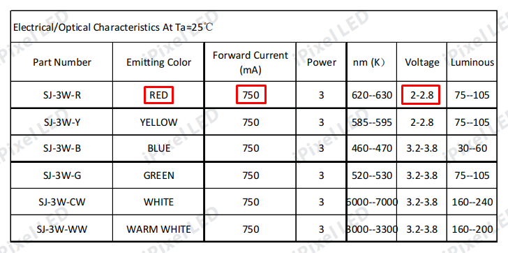
Looking at the datasheet for the specific 3W Red LEDs it can be seen that we need 2-2.8 Forward Voltage and 750mA Forward Current to be supplied by our LED Driver to drive one High Power 3W Red LED. Forward Voltage is the voltage in which Current starts to flow in the normal conducting direction. Forward Current of a diode is the maximum safe current you can continuously pass through the device without causing it damage.
LED Current and Voltage Requirements
LEDs are unlike other traditional incandescent lights where higher voltages produce brighter light. The amount of light (Lumens) an LED emits depends on how much current is supplied, see the diagram below. High-power LEDs can commonly take currents from 350mA to 3000mA. Too much current will result in thermal runaway and broken LEDs.
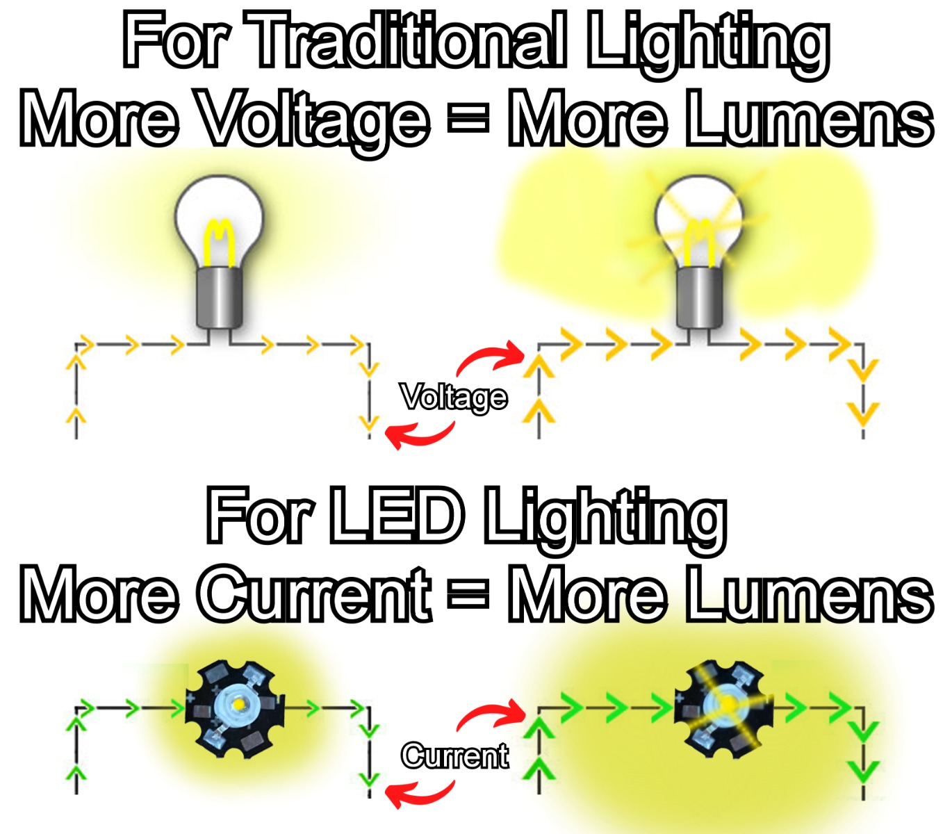
Now most power supplies are made to regulate voltage, not current. If you connected a standard DC voltage regulated power supply to a line of LEDs it would provide too much current to the LEDs and cause them to break. Just remember that LEDs are greedy for current and need somebody to supervise them otherwise they will become gluttons and die a very early life.
This is why we need a Constant Current LED Driver between the DC power supply and the LEDs. This acts as the supervisor. The LED driver can regulate the current and voltage provided to the LEDs so that they are always at the perfect level. These devices normally provide a range of voltages and currents which can be altered to precise levels by rotating the adjustment potentiometer. Setting the LED driver correctly means the LED system is never able to exceed the maximum current rating of the LEDs.
So, make sure to pick a LED Driver that can provide enough power for the LEDs (keeping in mind how voltages and currents add/multiply when components are connected in series or parallel). Once the LEDs are chosen these values can be confirmed through specification sheets. It is good to know what you are looking for from your lighting application. For example, if you want dimming then you need to choose a driver with dimming capabilities or be ready to incorporate a microcontroller into your system. The most appropriate LED driver for this (and most) applications would be a buck/boost converter.
In regard to selecting the right power supply, the output voltage needs to be at least a few volts higher than the total forward voltage rating of the LEDs. No matter what LED Driver you choose there will be some inefficiencies. Forward voltage is the voltage in which current starts to flow in the normal conducting direction, for each specific led this can be found on the specification sheet.
Choosing the Buck (Step-Down) or Boost (Step-Up) Converter as the LED Driver
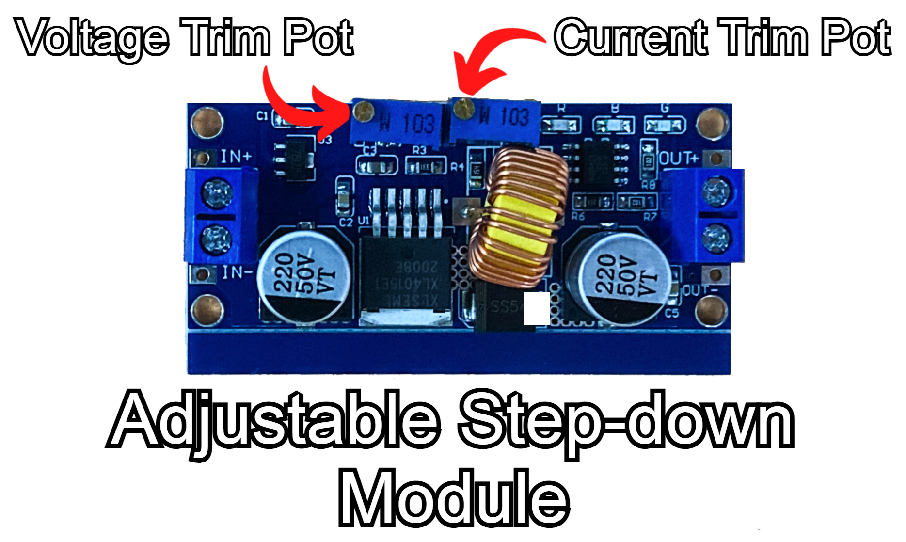
This DC-DC Adjustable Step-down Module 5A 75W (see this buck-converter in the image below) in combination with a 12 Volt 2 Amp DC Wall Power Supply will do perfectly for our purposes here.
A buck-boost converter is a type of DC-to-DC converter that has an output voltage magnitude that is either greater than or less than the input voltage. The technology of buck, boost, and buck-boost converters are utilized around the world to provide regulated low-voltage DC/DC power in nearly every electronics market. Importantly for the LED Driving these devices manage and prevent excess current flow.
Depending on whether your incoming voltage from the Power Supply is too high or too low for the connected LEDs you will need to incorporate a buck or boost converter. If the voltage and current are too high for the LEDs (we will be receiving 12 Volts and 2 Amps directly from the DC Wall Power Supply) you will need a buck (step-down) converter, see the one used in this guide below. On the other hand, if the voltage is too low you will need a boost (step-up) converter.
There are other combinations of electronics that can manage current and voltage correctly for high-power LEDs (like Linear Regulator and 555 Timers for dimming) however using a buck/boost driver is the best everyday solution for driving LEDs. These are the low heat and reasonably high-efficiency solution to driving high-power LEDs.
Determine the Wire Gauge
Any 18AWG (American Wire Gauge) Wire will do perfectly for our purposes here. Stranded wire is preferable.
It is important to use the right gauge for the application. Too thin a wire will get hot and potentially heat the wire to the point where it will melt and break the circuit. To figure this out from scratch the best way is by using the great Webpage Engineers Toolbox. This lets us take our values from our planned system and determine an appropriate thickness of wire to provide us with a good factor of safety. Current through the system is the main factor to manage in regards to selecting a wire size for these comparatively Low Voltages. By comparatively Low Voltages, I mean less than 120 Volts. Voltage lower than this won't be melting wire insulation or air arcing or doing flashovers. For those curious, the highest ever voltage produced was done by Oak Ridge National Laboratory where they reached 25.5 MegaVolts with their Van de Graaf Generator. This organization also developed the first atomic bombs and has an annual budget of over 2.4 Billion USD. Back to what we're doing here, see below for a table from the Engineers Toolbox Website that covers AWG sizing with regards to the current through the system.

Schematics and Hardware Set-Up for One High Power LED
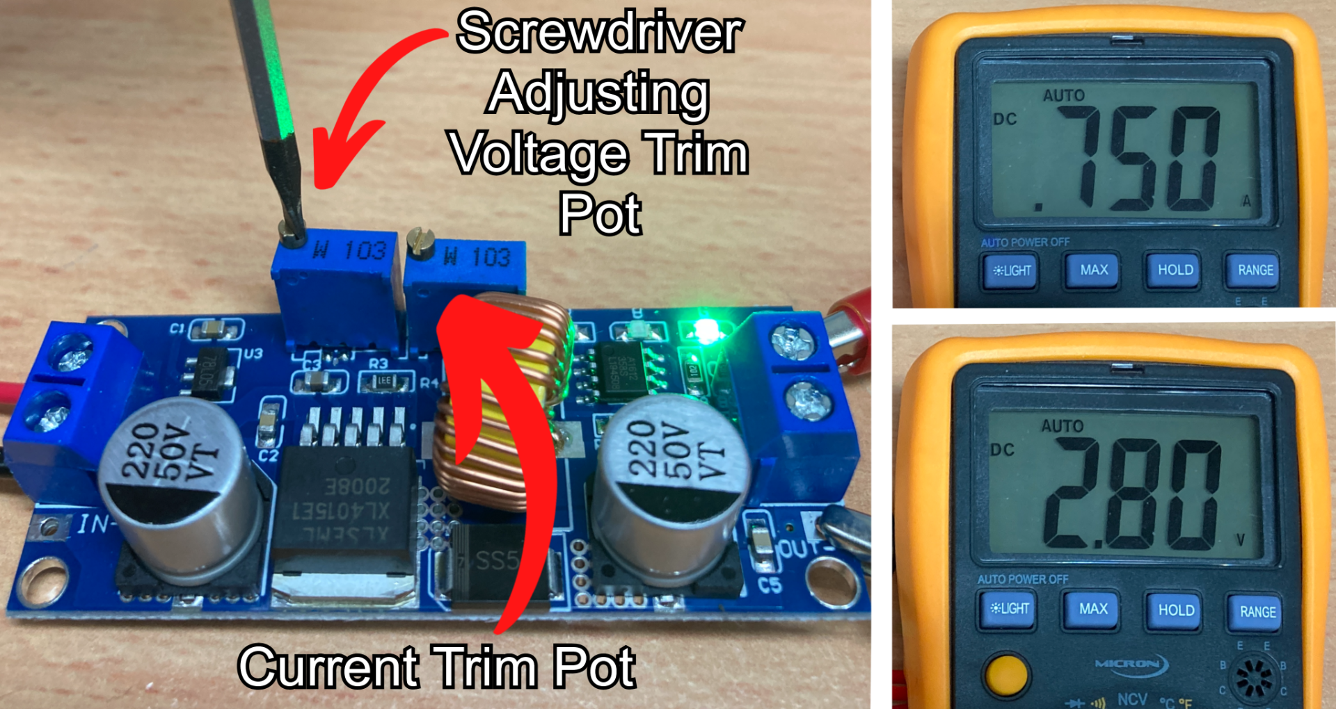
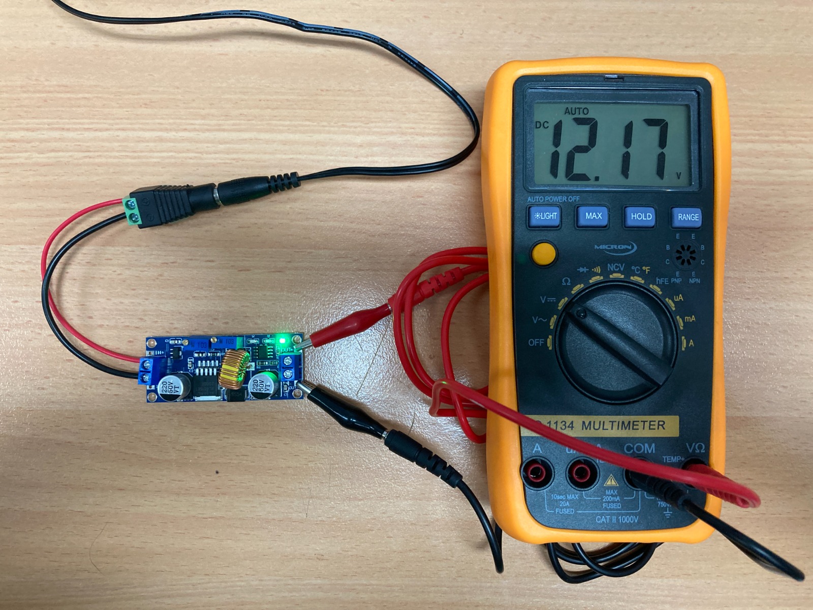
It is important before powering up that we have adjusted the Step-Down Module correctly. Thus, before connecting any LEDs do the following. Connect up the DC-DC Adjustable Step-Down Module to the Power supply and turn it on. Then using a multimeter connect the Red cord to the output + and the Black cord to the output – of the device. With this wired correctly to the Multimeter (see image below), we can then measure the current and voltage coming out of the LED Driver. Note that you need to move the Multimeter Red wire and adjust the Setting Wheel when measuring the current. See the Multimeter below hooked up to measure the stock voltage (left) or the stock current (right) that comes out of the Powered LED Driver. For a guide on using a Multimeter check here.

Looking at the datasheet for our 3W LEDs (which you can access here or on the product page in the specification). The important section of it can be seen in the image below. we can see we need a 2-2.8 Voltage and a 750mA Current to come out of our Step Down Module to drive One High Power 3W Red LED.
Now by adjusting the Screw Trim Potentiometer, as you can see in the annotated image below, we can now adjust it to our desired value. These LED drivers have two Trim Potentiometers that you can adjust with a screwdriver. These rotate around significantly more than anyone with experience of a normal potentiometer would realise. From the smallest voltage up to the highest, it takes 40+ full rotations. From the smallest current up to the highest output current, it takes 40+ rotations too. Adjust these so we can obtain the values that we found from the 3W LED Datasheet as you can see I've done in the image below.
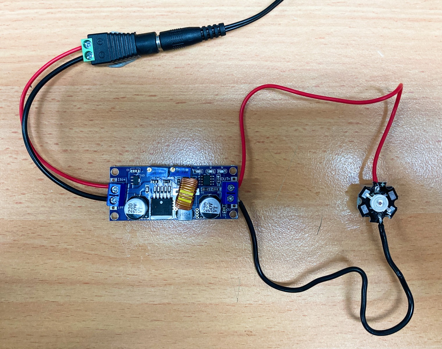
Below is the schematic of the setup we will do today. Very simple. I will only solder the sections I have no choice, which are the pads of the LED nodes. If I had chosen these LEDs no soldering would be required. All other connections are screw-down terminals. Bare, twisted stranded wire is best for screw-down terminals. Keep in mind that the 3W LED is mounted to a heatsink for thermal dispersion. Also, keep in mind that because LEDs are Diodes there are positive and negative terminals to connect to. If you connect these incorrectly it will break the LED node. On surface-mounted LEDs, the positive/negative terminal will be indicated by the PCB board. For Through-Hole LEDs the longer leg will be the positive side (you can remember this because to form a + symbol you need a longer length of material than if you were to form a – symbol).

So with all the parts selected and adjusted, based on the knowledge under our belts, procede to connect everything according to the schematic. With that complete whenever we power the system, we will see our LED light-up really, really bright! Don't stare directly at it when it is. Your eyes will thank me. See everything assembled below. The Star LED is sitting on a small Raspberry Pi heatsink.
Demonstration of Single LED Node
And now let's turn on our system! As soon as the power goes to the system the LED lights up, just check the image below. Note that the LED is mounted securely to a heatsink to dissipate the heat. After letting it run for approximately 10 minutes and it was perfectly okay.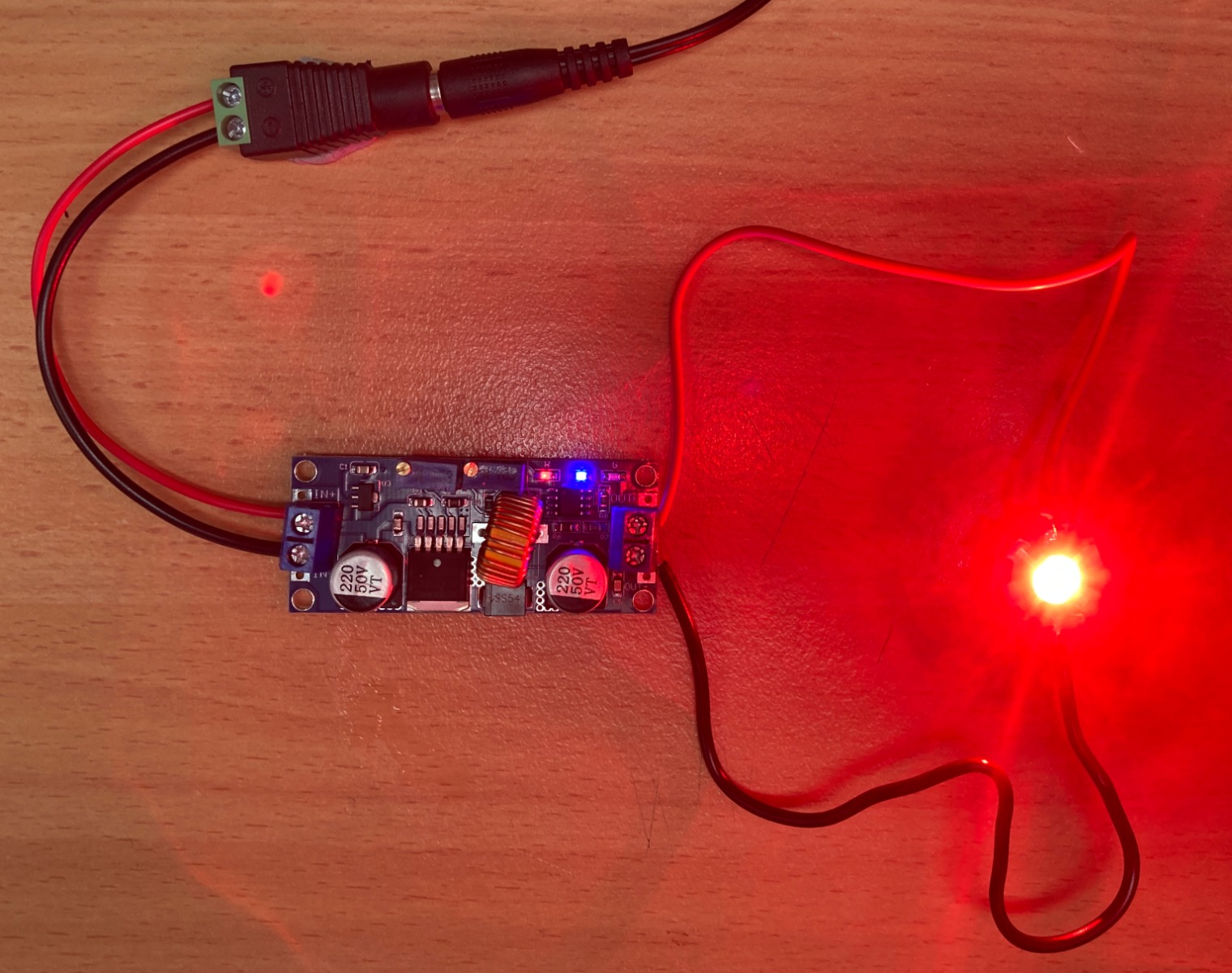
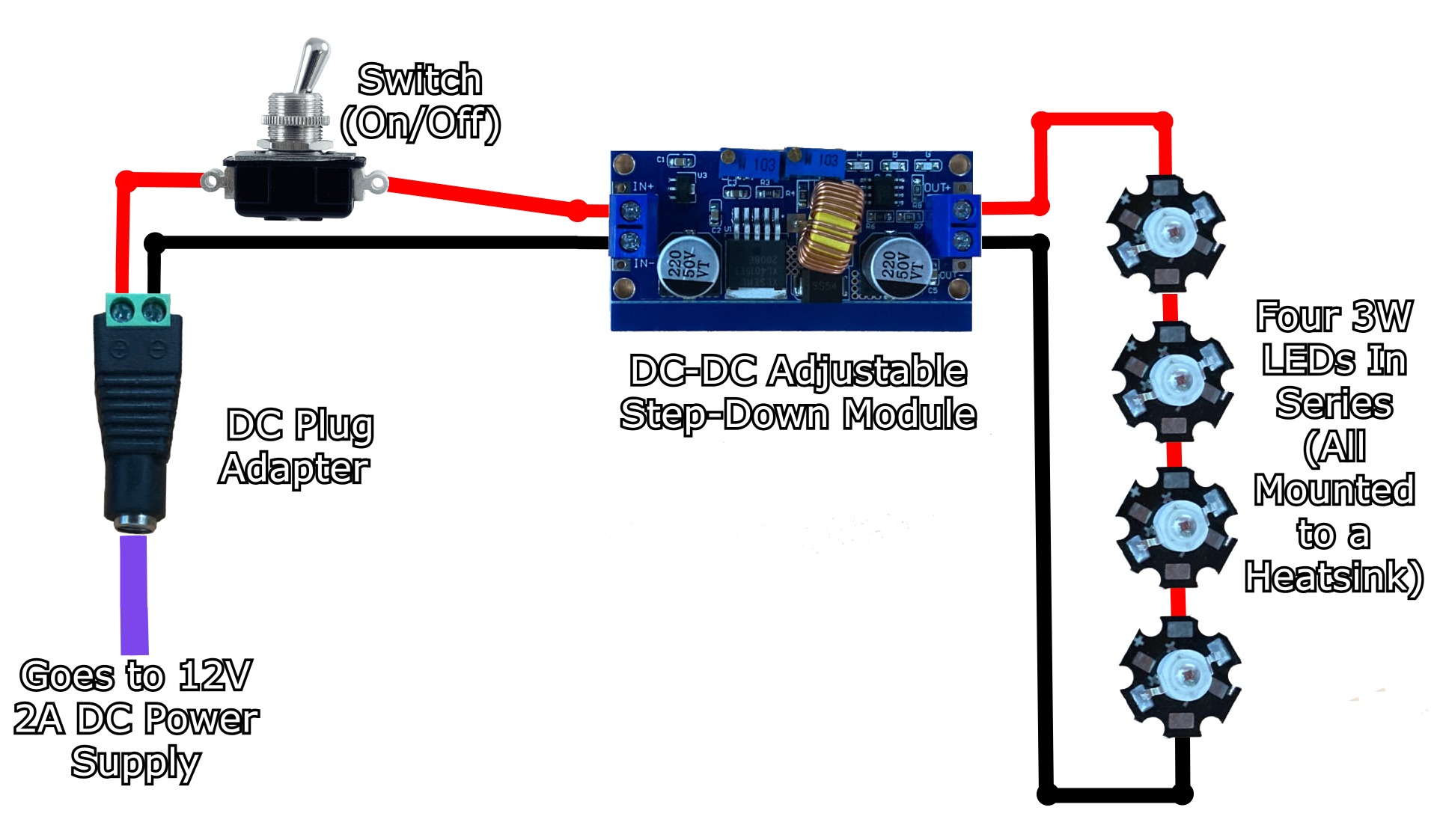
Schematics and Hardware Set-Up for Four High Power LEDs in Series with a Switch.
Now we are going to put four of these High Power 3W Red LEDs in series into the circuit just like the diagram below. Knowing that it is 4 of these LEDs in a row we know that the current draw can stay the same, however, we will need to increase the voltage. A Voltage of 2-2.8 Volts is needed for a single LED. Thus, for 4 we need 4 times as much which results in a required voltage of 8-12.2 Volts. Thus, we will need to use our Multimeter again and use it to set the Voltage Trim Potentiometer. The other new addition to this schematic is the added switch. With this, we can then have easy control of when we want the LEDs on and when we want the LEDs off.
Below is an image of using the Multimeter to set the correct voltage. The Adjustable Voltage Potentiometer was adjusted (over 20 full rotations) so that way the voltage could get to the 8-12.2 Volt range. As our LEDs are in series we will not need to adjust our current from the 750mA range.
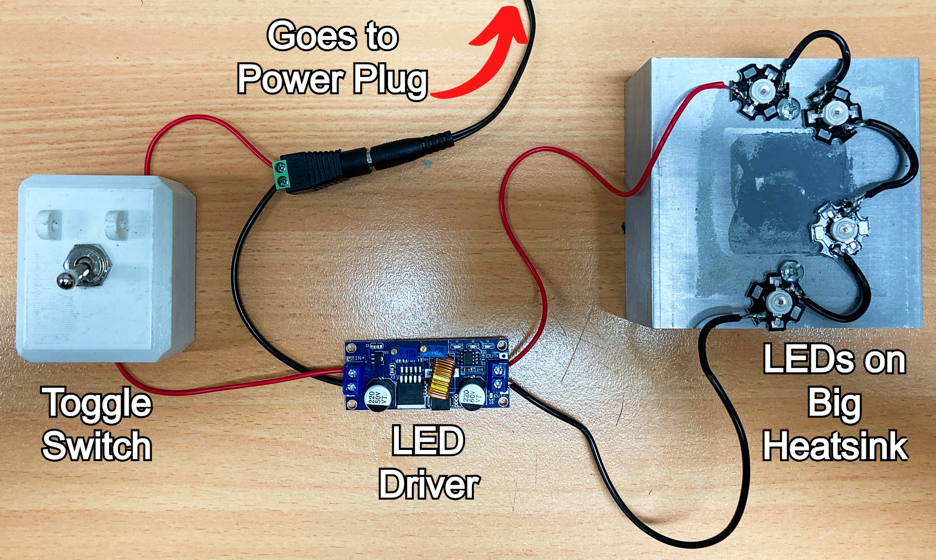
And below shows everything all wired up just like the schematic, with all the LED Nodes attached to an aluminum heat sink. This heatsink is overkill for these LEDs but it is convenient to show how you can screw them down onto surfaces thanks to their Star PCB shape. This aluminum heatsink came from pulling apart a Peltier thermoelectric cooler from Adafruit. You could use a simple bar of aluminum from a hardware store or use four little heat sinks like before.
Demonstration of 4 LED Nodes in Series
And now we can turn it on using the switch! As soon as power gets to the system the LED lights up really bright. Check the image below for exactly this and do try to avoid staring at them directly.

Where to Now - Other Colours, Dimming, 3D Printed Cases for Toggle Switch and LED Driver
So now not only do you have all the knowledge on part selection when it comes to high power LEDs but also exactly how to wire them up and harness their bright properties. Other colours are definitely available, from green, blue, red, warm white, cool white, or even triple output high power RGB LED (which would need to be wired up slightly different). There is even chainable 3W LED versions which means you wouldn’t need to solder any parts, check the image below.

Currently, we have them pushing out the maximum amount of light possible. If you wanted to add the ability to Dim the lights this is the perfect opportunity to use a micro-controller like an Arduino or ESP32 board. One thing microcontrollers are really good at is turning the current on and off very rapidly (using PWM). Switching on/off quickly enough can be a very effective and commonly used dimming method for high-power LEDs. You could also achieve this using a 555 timer, a potentiometer, and other componentry.
For this, I created an enclosure for the LED Driver and for the Switch. Both of these files are freely available online with locations here and here. Check the image below for both of these in action. If you don’t have a 3D printer you can find a similar Missle Switch Cover part here.


