
APM81815 Step-Down Voltage Regulator Carrier (5V)
A tiny buck regulator that turns up to 72 V into a steady 5 V at ~1.1 A, with up to 95% efficiency, soft-start, short-circuit and thermal protection, and an enable pin. 0.1" pads that suit breadboards and headers.
In stock, ships same business day if ordered before 2PM
Fastest delivery: Tomorrow*
Disclaimer:
For next-day delivery, the shipping address must
be in the AusPost next-day network, eParcel Express must be selected, and the order must be placed
before 2PM AEST Mon-Thurs excluding NSW Public Holidays. Orders may be delayed due to AusPost
pickup timings and order verifications. eParcel Express is typically a 1-day service within the
AusPost next-day network, though it is sometimes 2+ days.
We are offering these carrier boards with support from Pololu and Allegro Microsystems as an easy way to use or evaluate their APM81815 step-down voltage regulators; we therefore recommend referencing the APM81815 datasheet (2MB pdf) for detailed documentation of the regulator IC operation.
The APM81815 is a synchronous buck (step-down) voltage regulator that generates lower voltages from input voltages as high as 72 V (80 V absolute maximum). They are switching regulators (also called switched-mode power supplies (SMPS) or DC-to-DC converters), which makes them much more efficient than linear voltage regulators, especially when the difference between the input and output voltage is large. On our boards at room temperature and with no additional heat sinking or airflow, these regulators can typically support continuous output currents between 0.5 A and 1.5 A, depending on the input voltage and output voltage (see the Maximum continuous output current section below). In general, the available output current decreases as the input voltage increases.
This family includes four versions, one for each output voltage supported by the APM81815:
| Item # | Output voltage | Typical max output current(1) |
Input voltage range(2) | Size |
|---|---|---|---|---|
| #5266 | 3.3 V | 1.1 A | 5 V – 72 V | 0.4″ × 0.75″ |
| #5267 | 5 V | 1.1 A | 5.05 V – 72 V | |
| #5268 | 5.35 V | 1.1 A | 5.4 V – 72 V | |
| #5269 | 12 V | 0.8 A | 12.1 V – 72 V | |
| Note 1: At 48 V in. Actual achievable continuous output current is a function of input voltage and is limited by thermal dissipation. See the output current graphs on the product pages for more information. | ||||
| Note 2: Minimum input voltage is subject to dropout voltage considerations; see the dropout voltage section of product pages for more information. | ||||
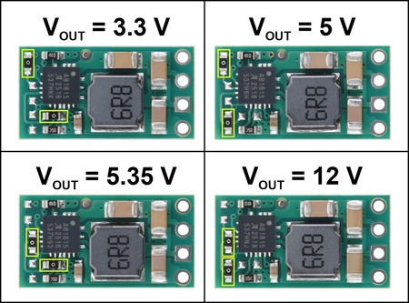
Four output voltage options are available, with the voltage determined by how a pair of zero-ohm resistors are populated.
The regulators feature short-circuit protection and thermal shutdown protection, which helps prevent damage from overheating. The boards do not have built-in protection against reverse voltage, but reverse-voltage protection modules are available for adding that functionality.
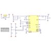
Schematic diagram
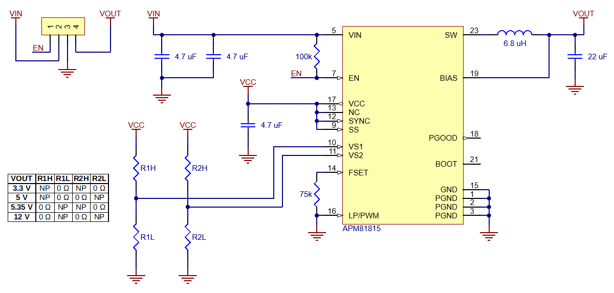
Schematic diagram of the APM81815 Step-Down Voltage Regulator Carrier.
Details for this version
This APM81815 is configured to output a fixed 5V.
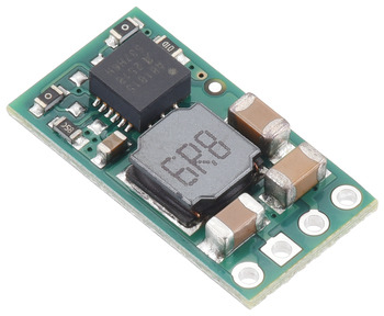
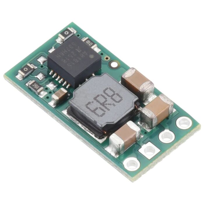
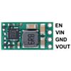
APM81815 Step-Down Voltage Regulator Carrier, 5V Out.
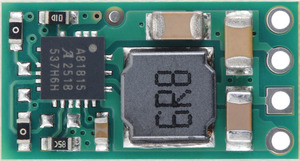
APM81815 Step-Down Voltage Regulator Carrier, 5V Out.
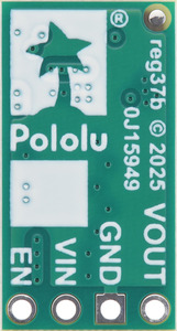
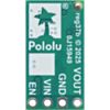
APM81815 Step-Down Voltage Regulator Carrier, bottom view.
Features
- Input voltage: 5.05 V to 72 V (80 V absolute max)
- Output voltage: 5 V with 2% accuracy
- Typical maximum continuous output current: 0.5 A to 1.5 A (see the maximum continuous output current graph below)
- Typical efficiency of 55% to 95%, depending on input voltage and load (see the efficiency graph below)
- Switching frequency: ~1 MHz under heavy loads
- < 0.1 mA typical no-load quiescent current (see the quiescent current graph below)
- Optional enable input with precision threshold can be used for simple on/off control or to implement a custom low-voltage cutoff
- Soft-start feature limits inrush current and gradually ramps output voltage
- Short-circuit and over-temperature protection
- PCB is 4-layer, 2-oz copper for improved thermal dissipation
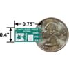
- Small size: 0.4″ × 0.75″ × 0.13″ (10.2 mm × 19.1 mm × 3.2 mm)
- Weight: 1.0 g
Connections
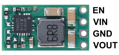
Pinout of the APM81815 Step-Down Voltage Regulator Carrier.
This regulator has four connections: enable (EN), input voltage (VIN), ground (GND), and output voltage (VOUT).
The input voltage, VIN, powers the regulator. Voltages between 5 V and 72 V can be applied to VIN, but generally the effective lower limit of VIN is VOUT plus the regulator’s dropout voltage, which varies approximately linearly with the load (see below for graphs of the dropout voltage as a function of the load). Additionally, please be wary of destructive LC spikes (see below for more information).
VOUT is the regulated output voltage.
The regulator, which is enabled by default, can be put into a low-power state that disables the output by reducing the voltage on the EN pin below 1.05 V (typical), and it can be brought out of this state again by increasing the voltage on EN past 1.2 V (typical; the actual rising threshold can vary between 1.15 V and 1.25 V). The shutdown current draw in this sleep mode is dominated by the current through the 100 kΩ pull-up resistor between EN and VIN, resulting in approximately 10-20 μA per volt on VIN. (Note that the shutdown current draw when the regulator is disabled can be greater than the quiescent draw while enabled; see the quiescent current graph below for more details.)
The four connections are labeled on the back side of the PCB and are arranged with a 0.1″ spacing along the edge of the board for compatibility with solderless breadboards, connectors, and other prototyping arrangements that use a 0.1″ grid. You can solder wires or 0.1″ header pins directly to the board. Note: header pins are not included with this product, but 1×4 straight male headers and 1×4 right-angle male headers are available separately.
Typical efficiency
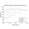
The efficiency of a voltage regulator, defined as (Power out)/(Power in), is an important measure of its performance, especially when battery life or heat are concerns.
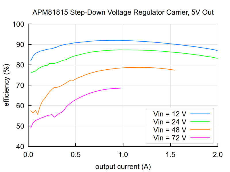
Typical efficiency of the APM81815 Step-Down Voltage Regulator Carrier, 5V Out.
Maximum continuous output current
The maximum achievable output current of these regulators varies with the input voltage but also depends on other factors, including the ambient temperature, air flow, and heat sinking. The graph below shows maximum output currents that these APM81815 regulators can deliver continuously on our boards at room temperature in still air and without additional heat sinking.
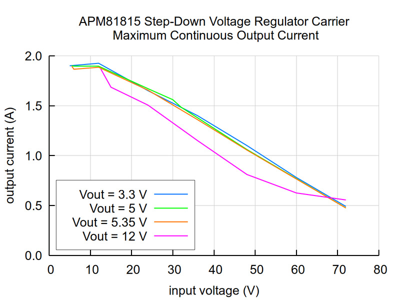
Typical maximum continuous output current of the APM81815 Step-Down Voltage Regulator Carrier.
During normal operation, this product can get hot enough to burn you. Take care when handling this product or other components connected to it.
Quiescent current
The quiescent current is the current the regulator uses just to power itself, and the graph below shows this for the different regulator versions as a function of the input voltage.
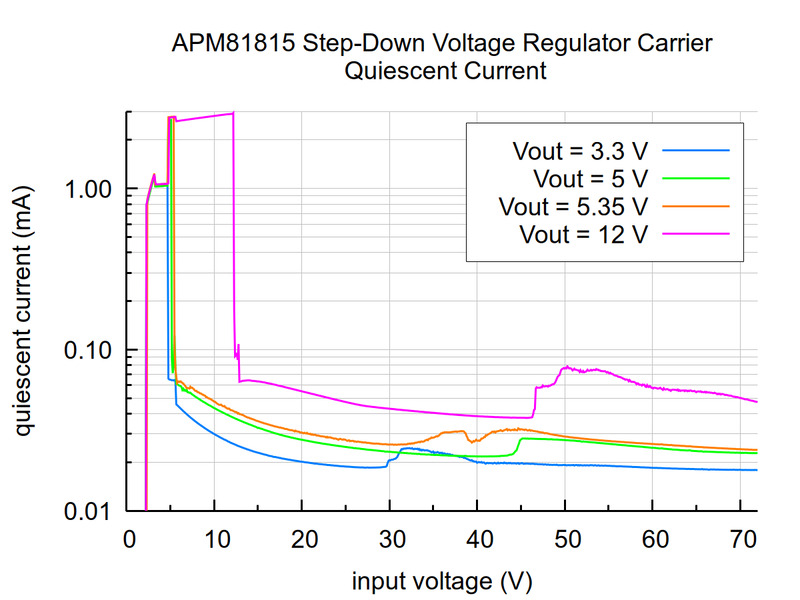
Typical quiescent current of the APM81815 Step-Down Voltage Regulator Carrier.
Typical dropout voltage
The dropout voltage of a step-down regulator is the minimum amount by which the input voltage must exceed the regulator’s target output voltage in order to ensure the target output can be achieved. For example, if a 5 V regulator has a 1 V dropout voltage, the input must be at least 6 V to ensure the output is the full 5 V. Generally speaking, the dropout voltage increases as the output current increases. (Note that for the 3.3 V version, the dropout is at least 1.7 V due to the regulator’s 5 V minimum operating voltage.) The graphs below shows the dropout voltages for the four different regulator versions as a function of output current.
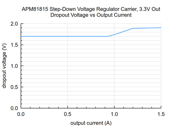
Typical dropout voltage of the APM81815 Step-Down Voltage Regulator Carrier, 3.3V Out.
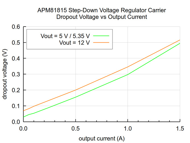
Typical dropout voltage of the APM81815 Step-Down Voltage Regulator Carrier (5V output versions and above).
LC voltage spikes
When connecting voltage to electronic circuits, the initial rush of current can cause voltage spikes that are much higher than the input voltage. If these spikes exceed the regulator’s absolute maximum voltage (80 V), the regulator can be destroyed. In our tests with typical power leads (~30″ test clips), we observed spikes approaching the maximum recommended operating voltage of 72 V at input voltages approaching 40 V. Power supplies or leads with high inductance will make these spikes worse. An electrolytic capacitor (47 μF is a good starting point) can be added close to the regulator between VIN and GND to help suppress these spikes.
More information about LC spikes can be found in our application note, Understanding Destructive LC Voltage Spikes.
Exact shipping can be calculated on the view cart page (no login required).
Products that weigh more than 0.5 KG may cost more than what's shown (for example, test equipment, machines, >500mL liquids, etc).
We deliver Australia-wide with these options (depends on the final destination - you can get a quote on the view cart page):
- $3+ for Stamped Mail (typically 10+ business days, not tracked, only available on selected small items)
- $7+ for Standard Post (typically 6+ business days, tracked)
- $11+ for Express Post (typically 2+ business days, tracked)
- Pickup - Free! Only available to customers who live in the Newcastle region (must order online and only pickup after we email to notify you the order is ready). Orders placed after 2PM may not be ready until the following business day.
Non-metro addresses in WA, NT, SA & TAS can take 2+ days in addition to the above information.
Some batteries (such as LiPo) can't be shipped by Air. During checkout, Express Post and International Methods will not be an option if you have that type of battery in your shopping cart.
International Orders - the following rates are for New Zealand and will vary for other countries:
- $12+ for Pack and Track (3+ days, tracked)
- $16+ for Express International (2-5 days, tracked)
If you order lots of gear, the postage amount will increase based on the weight of your order.
Our physical address (here's a PDF which includes other key business details):
40 Aruma Place
Cardiff
NSW, 2285
Australia
Take a look at our customer service page if you have other questions such as "do we do purchase orders" (yes!) or "are prices GST inclusive" (yes they are!). We're here to help - get in touch with us to talk shop.
Have a product question? We're here to help!
 Logic Level Converter Bi-DirectionalSKU: CE07510 Brand: MakerverseThis Bi-Directional Logic Level Converter is a breadboard-friendly device that c ...
- Makerverse USB-C LiPo ChargerSKU: CE08374 Brand: Makerverse
A battery charger with selectable charge currents and USB-C!
- DC-DC Multi-output Buck Converter (3.3V/5V/9V/12V)SKU: DFR1015 Brand: DFRobotThis DC-DC Step Down Voltage Converter steps down voltage from 7.5V~30V to 3.3V/ ...
- Pibow Frame for Raspberry Pi Touch Display 2 (10.1") – Noir BlackSKU: PIM793 Brand: Pimoroni
Prop your Pi 5 touchscreen at any angle, protect its exposed back, and keep e ...


- Logic Level Converter Bi-DirectionalSKU: CE07510 Brand: MakerverseThis Bi-Directional Logic Level Converter is a breadboard-friendly device that c ...
- Super Bright Red 5mm LED (25 pack)SKU: ADA297 Brand: AdafruitNeed some really bright LEDs? Adafruit are big fans of these clear red LEDs, in ...
- Super Bright Blue 5mm LED (25 pack)SKU: ADA301 Brand: AdafruitNeed some really bright LEDs? Adafruit are big fans of these clear blue LEDs, in ...
- Super Bright Green 5mm LED (25 pack)SKU: ADA300 Brand: AdafruitNeed some really bright LEDs? Adafruit are big fans of these clear green LEDs, i ...


Videos
View AllGuides

PiicoDev Magnetometer- Getting Started Guide
How to Drive High Power LEDs – 3W Aluminum Backed Star LEDs

The Maker Revolution
How to Use DC Regulators/Converters
Projects
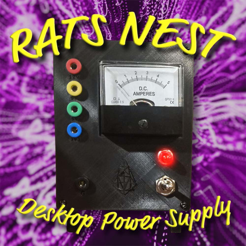
The Rats Nest VCC Desktop Power Supply
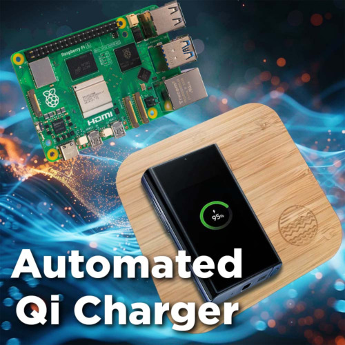
Wireless QI Phone Charger Powered by Raspberry Pi
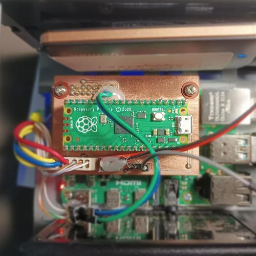
mmPi-Pico HAT

Makers love reviews as much as you do, please follow this link to review the products you have purchased.
Product Comments