
5V Step-Up/Step-Down Voltage Regulator S9V11E2F5
A compact 5 V buck-boost regulator that holds a steady output from 3 V to 16 V inputs, supplying up to 1.7 A at typical efficiencies of 85% to 95%.
Available with a lead time
Expect dispatch between Oct 29 and Nov 02
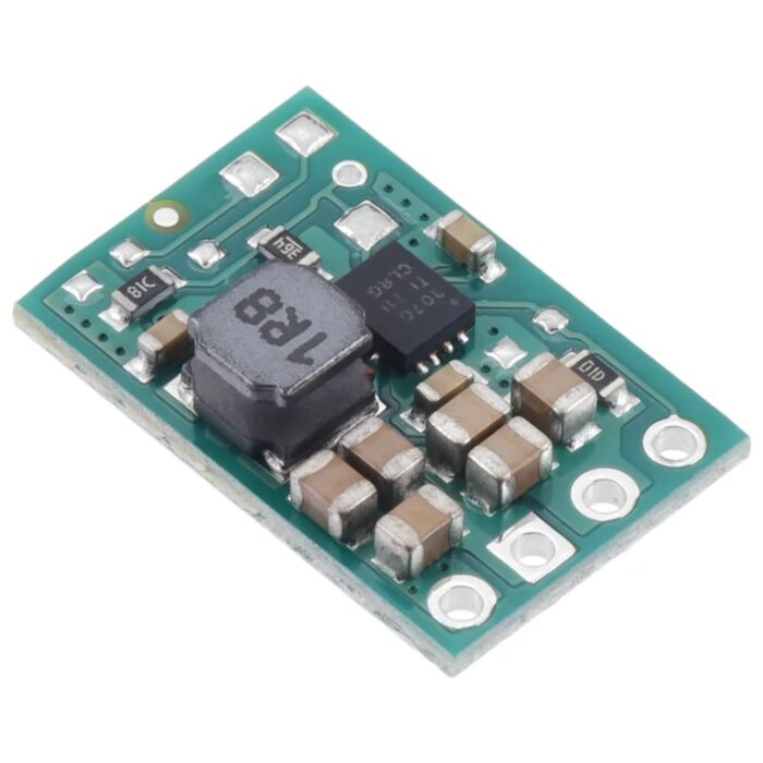
The S9V11E2F5 is a compact buck-boost switching regulator from Pololu's S9V11x family. It delivers a fixed 5 V output from input voltages between 2 V and 16 V (3 V is needed to start). It supplies a maximum continuous output current of 1.7 A for input voltages close to or greater than the output. The board measures 0.43″ × 0.65″ × 0.16″ (10.9 × 16.5 × 4.0 mm).
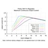
The 1.7 A rating applies after startup. Startup current is limited to approximately 700 mA until the output voltage reaches the nominal voltage. After startup, the actual achievable maximum continuous current is a function of input and output voltage and is limited by thermal dissipation. See the output current graph below for more information.
Overview

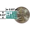
Step-Up/Step-Down Voltage Regulator S9V11E2x, bottom view with dimensions and a US quarter for size reference.
The S9V11x family of efficient switching regulators (also called switched-mode power supplies (SMPS) or DC-to-DC converters) uses a buck-boost topology to convert both higher and lower input voltages to a regulated output voltage. They take input voltages from 2 V to 16 V and increase or decrease them as necessary. They offer typical efficiencies of 85% to 95% and typical continuous output currents over 1.5 A for input voltages close to or greater than the output voltage. (Note: The minimum start-up voltage is 3 V, but the regulator will operate down to 2 V after startup.)
This flexibility in input voltage suits battery-powered applications especially well, where the battery voltage starts above the regulated voltage and drops below it as the battery discharges. Without the usual restriction of keeping the battery voltage above the required voltage throughout its life, new battery packs and form factors can be considered.
These regulators have short-circuit protection, and thermal shutdown prevents damage from overheating. The boards do not have built-in protection against reverse voltage, but reverse-voltage protection modules are available for adding that functionality. Note that the startup current is limited to approximately 700 mA until the output voltage reaches the nominal voltage. After startup, the available current is a function of the input voltage (see the maximum continuous output current graph below).
The different members of this family offer different output voltage options. These range from fixed voltages (some with selectable alternatives) to adjustable voltages that can be set anywhere between 2.5 V and 9 V. Some versions also have an adjustable low-voltage cutoff that can be set anywhere from 2 V to 16 V and used to prevent your battery from over-discharging. This is particularly useful for battery chemistries that can be damaged when over-discharged, including Li-ion and LiPo. Across the family, fixed-output versions are offered at 3.3 V, 5 V, 6 V, 7.5 V and 9 V. All versions share the 2 V – 16 V input range (3 V startup).
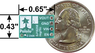
Step-Up/Step-Down Voltage Regulator S9V11E2x, bottom view with dimensions and a US quarter for size reference.
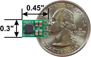
Pololu 5V Step-Up/Step-Down Voltage Regulator S9V11F5 next to a US quarter dollar for size reference.
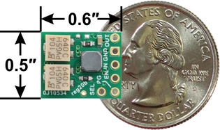
2.5-9V Fine-Adjust Step-Up/Step-Down Voltage Regulator w/ Adjustable Low-Voltage Cutoff S9V11MACMA next to US quarter dollar for size reference.
Details for this version
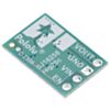
This item is the S9V11E2F5, which outputs a fixed 5 V. The different versions of the S9V11E2Fx regulators all look very similar. To help tell them apart, the bottom silkscreen includes a blank space where you can add your own distinguishing marks or labels.

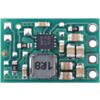
5V Step-Up/Step-Down Voltage Regulator S9V11E2F5.

5V Step-Up/Step-Down Voltage Regulator S9V11E2F5.
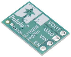
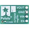
Step-Up/Step-Down Voltage Regulator S9V11E2x, bottom view.
Features
- Input voltage: 2 V to 16 V (note: this regulator requires 3 V to start, but it can operate down to 2 V after startup)
- Fixed 5 V output with +5/-3% accuracy
- Max continuous output current when input voltage ≥ output voltage: 1.7 A (note: startup current is limited to 700 mA until output voltage reaches the nominal voltage; see the maximum continuous output current graph below for current capabilities across the full input voltage range)
- Low quiescent current: < 0.2 mA for most of the operating range (see the quiescent current graph below)
- Enable input can be used to put the board into a low-power state where it typically draws 10 µA per volt on VIN
- Soft-start feature limits inrush current and gradually ramps output voltage
- Integrated over-temperature and short-circuit protection
- Power-saving feature maintains high efficiency at low currents
- Compact size: 0.43″ × 0.65″ × 0.16″ (10.9 × 16.5 × 4.0 mm); the dimension diagram listed under Resources below has more information
Using the Regulator
Connections
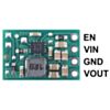
The S9V11E2x step-up/step-down regulator has four connections: the output voltage (VOUT), ground (GND), the input voltage (VIN), and an enable input (EN).
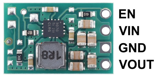
Pinout of the Step-Up/Step-Down Voltage Regulator S9V11E2x.
The input voltage, VIN, should be between 3 V and 16 V when the regulator is first powered. After the regulator is running, it can continue operating down to 2 V. Lower inputs can shut down the voltage regulator, and higher inputs can destroy the regulator. Make sure that noise on your input is not excessive, and be wary of destructive LC spikes (see the LC voltage spike section below for more information).
VOUT is the regulated output voltage. The regulator's soft-start feature gradually ramps up the VOUT voltage on start-up to limit inrush current draw.
The regulator is enabled by default. It can be put into a low-power sleep state by reducing the voltage on EN below 0.7 V, and brought out of this state again by increasing the voltage on EN past 0.8 V. The quiescent current draw in this sleep mode is dominated by the current in the 100 kΩ pull-up resistor from EN to VIN. This is approximately 10 µA per volt on VIN (e.g. approximately 30 µA with 3 V in). The tight tolerance of the enable input allows a precise low-VIN cutoff to be set, such as with the output of an external voltage divider powered by VIN. This is useful for battery-powered applications where draining the battery below a particular voltage threshold could permanently damage it.
The four connections are labelled on the back side of the PCB. They are arranged with a 0.1″ (2.54 mm) spacing along the edge of the board for compatibility with solderless breadboards, connectors, and other prototyping arrangements that use a 0.1″ grid. You can solder wires or 0.1″ header pins directly to the board. Note: header pins are not included with this product, but 1×4 straight male headers and 1×4 right-angle male headers are available separately.
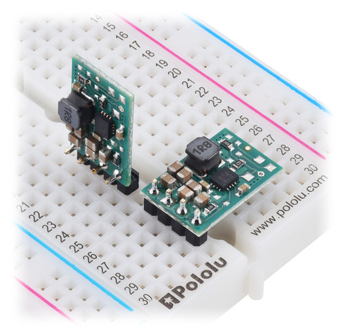
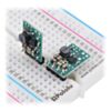
S9V11E2x step-up/step-down voltage regulators, soldered with straight and right-angle headers (not included), on a breadboard.
Typical efficiency
The efficiency of a voltage regulator, defined as (Power out)/(Power in), is an important measure of its performance, especially when battery life or heat are concerns.

Typical efficiency of Step-Up/Step-Down Voltage Regulator S9V11x with VOUT set to 5V.
Maximum continuous output current
The maximum achievable output current of the regulator varies with the input voltage. It also depends on other factors, including the ambient temperature, air flow, and heat sinking. The graph below shows the maximum output currents that the regulators in the S9V11x family can deliver continuously at room temperature in still air, without additional heat sinking. (Note: this graph does not apply to the smaller S9V11F5, which has lower output current capabilities due to its more compact PCB; see the graphs on its product page for more information.)
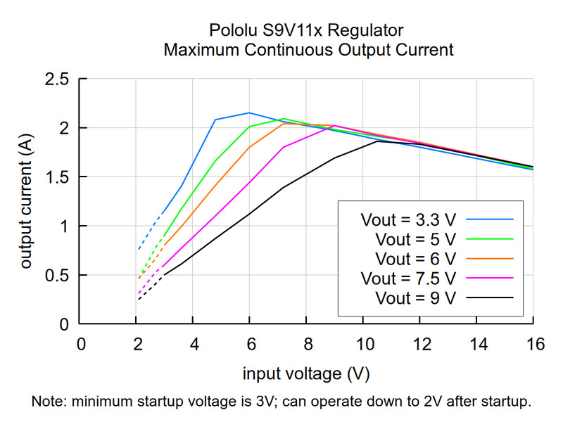
Typical maximum continuous output current of Step-Up/Step-Down Voltage Regulator S9V11x.
Note that the startup current is limited to approximately 700 mA. Currents in excess of this are only available after the output has finished rising to 5 V. Large capacitive loads will generally not pose a problem because they will gradually charge up even with the current limit active. They may increase the time it takes the regulator to start up, but the regulator should still eventually reach 5 V. A purely resistive load, however, could prevent the regulator from ever reaching 5 V. For example, if you put a 5 Ω resistor between VOUT and GND and then apply power to the regulator, the output voltage will never rise past 3.5 V, the voltage at which the current draw reaches the 700 mA limit. As such, this regulator is intended for applications like robotics, where any large loads are controllable and can be applied only after the regulator has finished starting up.
During normal operation, this product can get hot enough to burn you. Take care when handling this product or other components connected to it.
Quiescent current
The quiescent current is the current the regulator uses just to power itself, and the graph below shows this as a function of the input voltage. The module's EN input can be driven low to put the board into a low-power state where it typically draws 10 µA per volt on VIN.
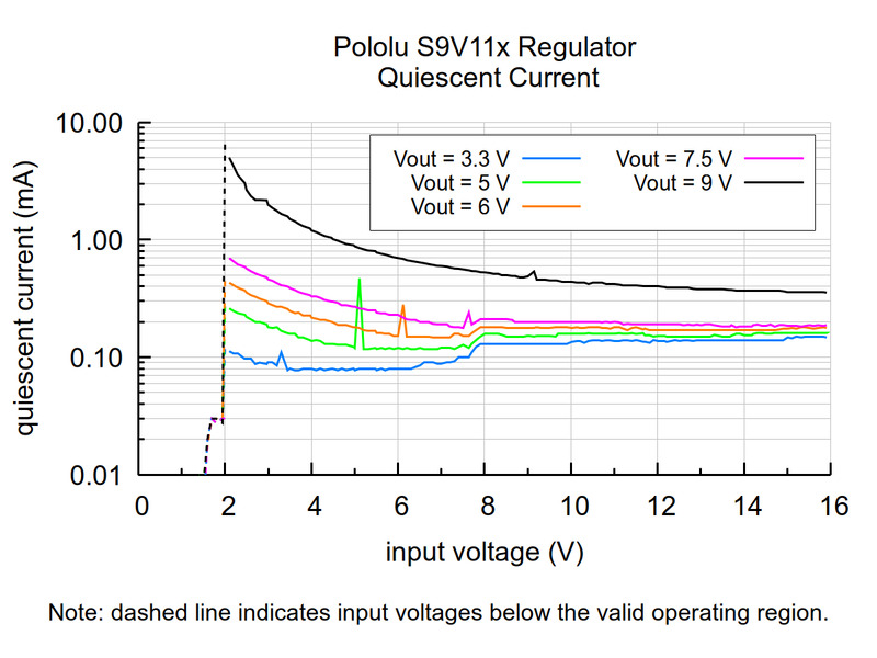
Typical quiescent current of the Step-Up/Step-Down Voltage Regulator S9V11x.
LC voltage spikes
When connecting voltage to electronic circuits, the initial rush of current can cause voltage spikes that are much higher than the input voltage. If these spikes exceed the regulator's maximum voltage (16 V), the regulator can be destroyed. In Pololu's tests with typical power leads (~30″ (76 cm) test clips), spikes approaching 16 V were observed at input voltages approaching 9 V. Power supplies or leads with high inductance will make these spikes worse. An electrolytic capacitor (33 μF is a good starting point) can be added close to the regulator between VIN and GND to help suppress these spikes.
Pololu's application note on destructive LC voltage spikes, listed under Resources below, covers LC spikes in more detail.
Resources
Exact shipping can be calculated on the view cart page (no login required).
Products that weigh more than 0.5 KG may cost more than what's shown (for example, test equipment, machines, >500mL liquids, etc).
We deliver Australia-wide with these options (depends on the final destination - you can get a quote on the view cart page):
- $3+ for Stamped Mail (typically 10+ business days, not tracked, only available on selected small items)
- $7+ for Standard Post (typically 6+ business days, tracked)
- $11+ for Express Post (typically 2+ business days, tracked)
- Pickup - Free! Only available to customers who live in the Newcastle region (must order online and only pickup after we email to notify you the order is ready). Orders placed after 2PM may not be ready until the following business day.
Non-metro addresses in WA, NT, SA & TAS can take 2+ days in addition to the above information.
Some batteries (such as LiPo) can't be shipped by Air. During checkout, Express Post and International Methods will not be an option if you have that type of battery in your shopping cart.
International Orders - the following rates are for New Zealand and will vary for other countries:
- $12+ for Pack and Track (3+ days, tracked)
- $16+ for Express International (2-5 days, tracked)
If you order lots of gear, the postage amount will increase based on the weight of your order.
Our physical address (here's a PDF which includes other key business details):
40 Aruma Place
Cardiff
NSW, 2285
Australia
Take a look at our customer service page if you have other questions such as "do we do purchase orders" (yes!) or "are prices GST inclusive" (yes they are!). We're here to help - get in touch with us to talk shop.
Have a product question? We're here to help!
 Solder Leaded - 15-gram TubeSKU: TOL-09162 Brand: SparkfunThis is your basic tube of leaded solder with a 63/37 water soluble resin core. ...
- 499:1 Metal Gearmotor 25Dx58L mmSKU: POLOLU-1591 Brand: PololuThis cylindrical, 2.28" x 0.98" x 0.98" brushed DC gearmotor with a 498.87:1 met ...
- 24AWG White 4 Core Security Cable (per metre)SKU: AW2341 Brand: Core Electronics
If you need data and power somewhere far from your control box - grab some of ...
- 20 AWG Figure 8 Speaker Cable (per metre)SKU: AW2116 Brand: Core Electronics
Robust, audio-grade cable - Perfect when a little more power is needed.


Videos
View AllGuides

PiicoDev Magnetometer- Getting Started Guide

The Maker Revolution
How to Use DC Regulators/Converters
Powering Portable Projects: Batteries
Projects
The Rats Nest VCC Desktop Power Supply
Wireless QI Phone Charger Powered by Raspberry Pi
mmPi-Pico HAT

Makers love reviews as much as you do, please follow this link to review the products you have purchased.
Product Comments