The aim of this project was to use the sun to charge some batteries with 1W and 2W Seeed solar panels. The DFRobot Solar LiPo Charger and a Sunflower Solar Power Manager were purchased. Initially, this was unsuccessful because I did not realize the panels need full sun to produce full power. The LiPo was connected such that it was shaded by the panel but it still got a little too hot for my liking. The solution was to place the solar panel in the sun connected via a 3 meter cable to the charger inside the house. All the items listed work perfectly for charging LiPo batteries.
For charging phone, tablet, and power bank devices they receive a charge via a 5V USB port and can draw up to 2A or more. Investigation of my phone showed it would charge at 430mA from a computer USB port and 1.3A from the charger supplied with the phone. So minimum power would be 5V x 2A = 10W which was the aim for the project.
Bill of Materials: (major items only)
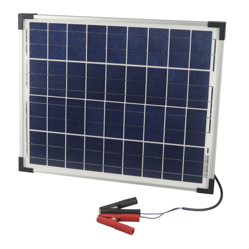
12V 20W Solar Panel with Clips Jaycar CAT.NO: ZM9052
Monocrystalline
Open Circuit Voltage: 22V
Short Circuit Current: 1.21A
Voltage at Power Max: 17.4V
Current at Power Max: 1.16A
Dimensions: 435 x 356 x 25 (LxWxH)
Warranty: 5 years, 20 years for power output no less than 80%
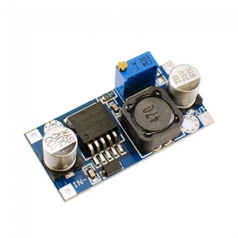
Adjustable Switching Power Supply Module IN 4V-35V OUT 1.5V-30V LM2596S SKU: CE05572
Input voltage: 4V to 35V DC
Output voltage: 1.23V to 30V
Output current: 3A max
Efficiency: 92%
Dimensions: 48 x 23 x 14 (LxWxH)
Design:
The 20W solar panel was chosen so it would provide enough charge when the sunlight conditions were not ideal; such as clouds or early morning / late afternoon. The panel would also be mounted outside on the house roof, so a long-life robust design was needed.
The power supply module was chosen due to its flexibility, power output and the ability to finely adjust the output level using the 20 turn pot. Although it will only be operated at 5V, it can be set to different output voltages in the future, if the situation changes. The large input range also allows for changes to the panel configuration.
Construction:
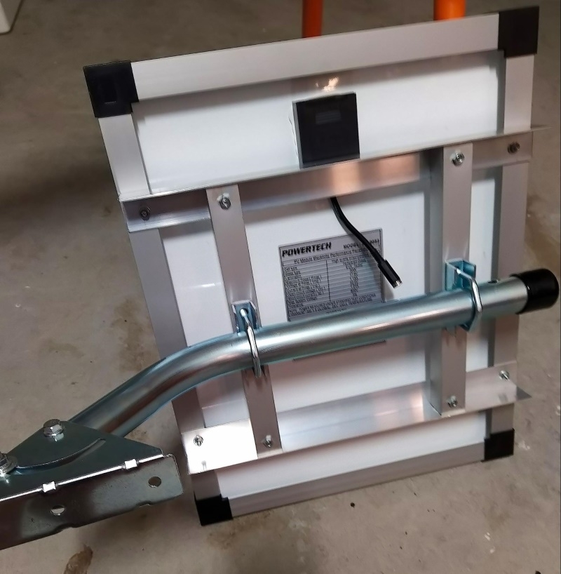
Solar Panel and mounting hardware.
The pics show the hardware that was purchased from Bunnings Warehouse and how it was put together. The end result is a fairly robust mount for the panel. The Antsig antenna mast worked very well for angling the panel to face the sun.
The original panel cable was too short to run from the roof to the garage so it was cut and a 2.1mm power plug installed. The connecting cable is an Automotive / Marine 7.5A power cable and is about 6 metres in length. If this was done again the cable would be soldered to the terminals inside the box on the panel. This would be more robust and reduce the chance of moisture ingress. The 2.1mm plug and connecting cable was used for flexibility in testing.

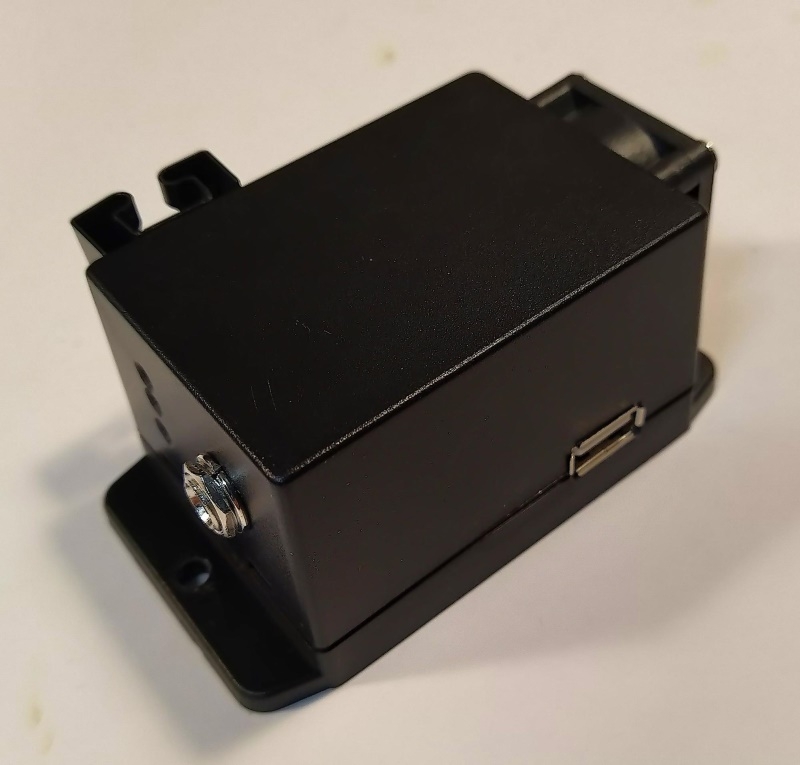
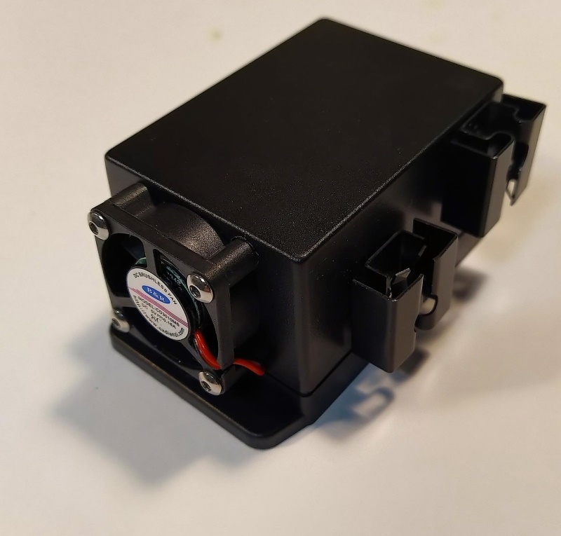
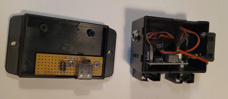
5V USB Power Supply
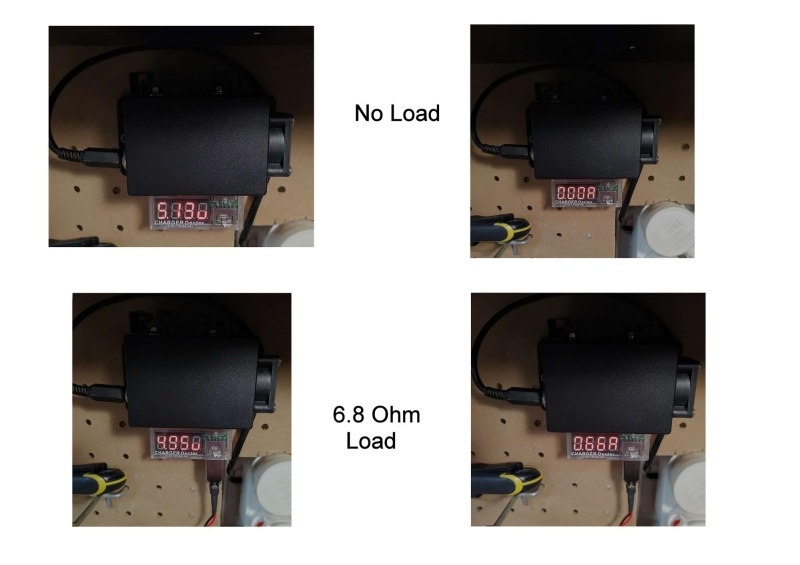
The switching power supply module was mounted inside a small jiffy box. A USB female connector mounted on a small Veroboard inside the box and a 2.1mm power plug socket installed at one end. A Raspberry Pi 5V fan is attached at the other end to remove heat from the box. A few small vent holes were made at the plug end to allow air to flow across the module. A Charge Doctor shows the voltage and current conditions on the USB port. Two small heat sinks were mounted to the module screws for heat dissipation.
A point to note here is the 2 mounting screws on the module are not at the same potential. One is connected to Vin+ the other to Vout-. Shorting Vin+ to Vout- (GND) would not be good. The design of the module does not allow for a heat sink to be easily attached.
Testing:
Solar Panel.
The solar panel produced around 20V with no load and maximum current around 17V with an ideal load. (as per the specifications) 5W & 10W resistors of various values were used to assess the best operating conditions.
Overload condition.
If the panel is overloaded, the voltage drops to a low level and stays there even if the load conditions are changed. ie full sun, then cloud, then full sun. Removal of the load is required to bring the panel back to full voltage. This mainly occurred when the panel was operating close to its full load capacity for the conditions. If it was operating at half its full potential then it would recover correctly if the output dropped briefly for any reason.
The same effect was noticed when the panel was disconnected from the power supply but the load remained attached to the supply. Connecting the panel in this situation would cause it not to work. Connecting the panel first, then the load, it would work correctly. Possibly the startup current of the power supply was too great. Again it happened only when close to its full capacity, less than full and it would work ok.
Power supply heat issue.
Initially, the box did not have a fan or heat sinks. Testing showed the mounting screws became very hot when providing the 1.3A to charge the phone for a few hours. Two small heat sinks were added to the mounting screws but did not change the heat output by very much. Adding the fan solved the heat problem. The heat sinks now get mildly warm and the overall temperature is at a good level.
Phone charge current issue.
Initially, the supply would only charge the phone at 430mA but was capable of providing over 2A. Why ??
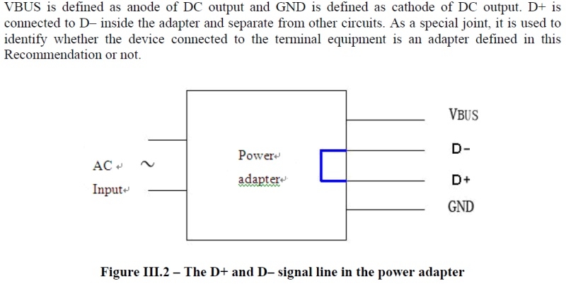
This proved to be because of the way the phone detects the difference between a PC USB port and a Phone charger plug pack. The charger simply connects the D+ and D- pins of the USB A connector inside the charger. The phone detects this connection and switches to a higher charge mode.
So, a jumper was installed on the D+ and D- pins on the Veroboard. The phone is now charged at 1.3A and takes about 2 to 3 hours to charge. At 430mA the phone takes about 6 to 8 hours to charge.
The following is from a recommended standard for phone charger plug packs.
TELECOMMUNICATION STANDARDIZATION SECTOR ITU-T L.1000 (03/2010)
Universal power adapter and charger solution for mobile terminals and other ICT devices
Ideal charging time.
Power is only available while the sun is shining. Testing has shown the usable power to charge the phone is from 9:00am to 3:00pm, at this time of year, where I am located. Most people use their phones during the day and recharge at night. But this is not an issue for me because of my situation. (retired)
Conclusion:
The solar charger has been used to charge a phone, a LiPo Christmas decoration and as a power supply for Arduino and Raspberry Pi projects. (the Christmas decoration has a USB charger installed)
It has worked successfully in all instances.
The savings in electricity to charge the phone is about $1 per charge, not a lot. It will take some time to recoup the cost of the project, but given the 20-year life span of the panel, it should pay for itself many times over.
When using solar panels consideration should be given to the available sunlight and location of the panel. A management device is recommended to ensure the maximum power is delivered from the panel for the current conditions. The amount of output can vary significantly during normal daylight hours. Even a small shadow can reduce the output by a significant amount.
This is a fairly simple project; a solar panel connected to a power supply, adding some form of management device would be a future improvement.
Overall I have learned a lot from this project about solar panels, their advantages, and limitations.
Check out the two forum topics where this project was discussed:

