


5V Step-Up/Step-Down Voltage Regulator S13V30F5
In stock, ships same business day if ordered before 2PM
Fastest delivery: Tomorrow*
Disclaimer:
For next-day delivery, the shipping address must
be in the AusPost next-day network, eParcel Express must be selected, and the order must be placed
before 2PM AEST Mon-Thurs excluding NSW Public Holidays. Orders may be delayed due to AusPost
pickup timings and order verifications. eParcel Express is typically a 1-day service within the
AusPost next-day network, though it is sometimes 2+ days.
Quantity Discounts:
- 10+ $26.27 (exc GST)
- 25+ $25.45 (exc GST)
 |
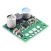
The S13VxF5 family of efficient switching regulators (also called switched-mode power supplies (SMPS) or DC-to-DC converters) use a buck-boost topology to convert both higher and lower input voltages to a regulated 5 V output. They take input voltages from 2.8 V to 22 V and increase or decrease them as necessary, offering a typical efficiency of over 85% and typical continuous output currents between 1 A and 3 A . The flexibility in input voltage offered by this family of regulators is especially well-suited for battery-powered applications in which the battery voltage begins above 5 V and drops below as the battery discharges. Without the typical restriction on the battery voltage staying above the required voltage throughout its life, new battery packs and form factors can be considered.
The different members of this family offer different continuous output currents:
- S13V10F5: 1 A continuous output current
- S13V15F5: 1.5 A continuous output current
- S13V20F5: 2 A continuous output current
- S13V30F5: 3 A continuous output current
The regulators have under-voltage lockout, output over-voltage protection, and over-current protection. A thermal shutdown feature also helps prevent damage from overheating and a soft-start feature limits the inrush current and gradually ramps the output voltage on startup. The larger 3 A S13V30F5 has reverse-voltage protection up to 20 V, but the S13V10F5, S13V15F5, and S13V20F5 do not.
 |
Details for item #4082
Features
- Input voltage: 2.8 V to 22 V
- Output voltage: 5 V with 3% accuracy
- Typical maximum continuous output current: 2 A to 4 A, depending on input voltage (see the maximum continuous output current graph below)
- Typical efficiency of 85% to 95%, depending on input voltage and load (see the efficiency graph below)
- 10 mA to 20 mA typical no-load quiescent current (see the quiescent current graph below); can be reduced to 2 µA to 10 µA per volt on VIN by disabling the board
- Input under-voltage lockout and output over-voltage protection
- Soft-start feature limits inrush current and gradually ramps output voltage
- Integrated reverse-voltage protection up to 20 V, over-current protection, and over-temperature shutoff
- Fixed switching frequency of ~500 kHz
- Compact size: 0.9" × 0.9" × 0.38" (22.9 mm × 22.9 mm × 9.7 mm); see the dimension diagram (294k pdf) for more information
- Two 0.086" mounting holes for #2 or M2 screws
 |
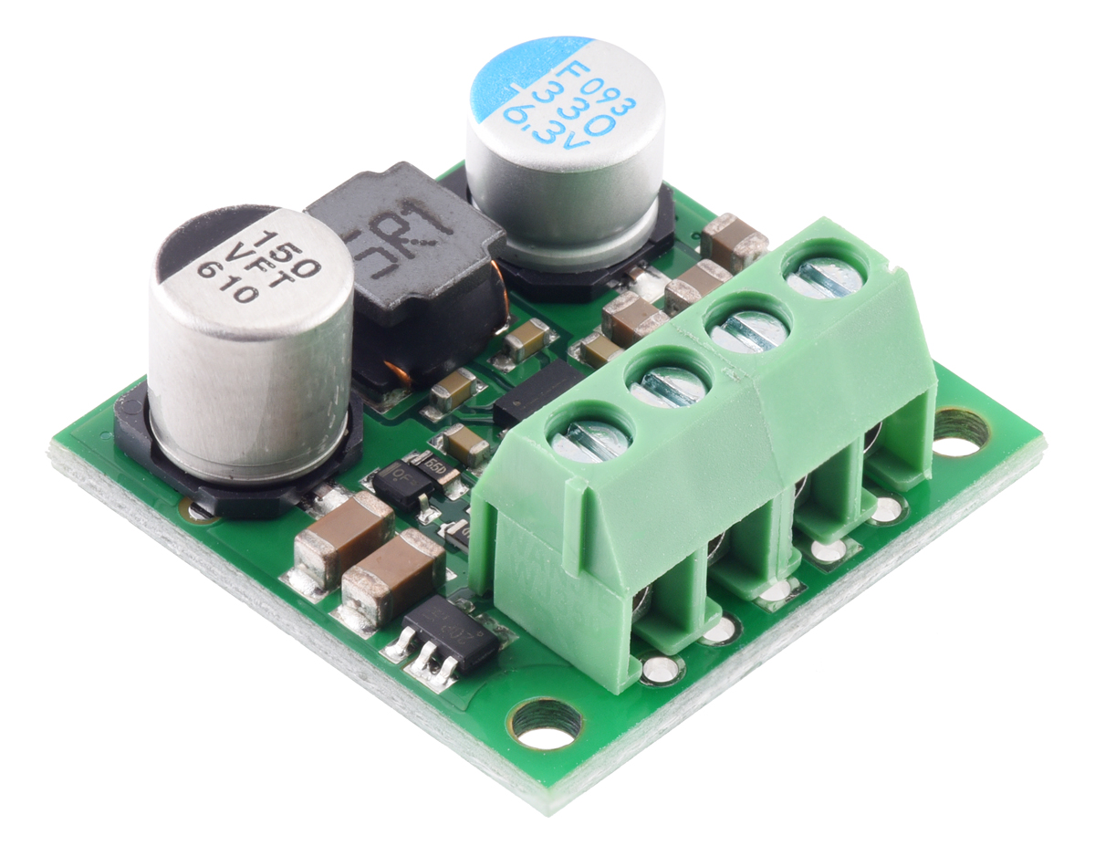
|
5V Step-Up/Step-Down Voltage Regulator S13V30F5, side view. |
|---|
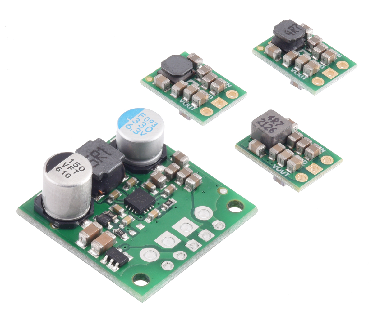
Connections
The step-up/step-down regulator has four connections: enable (EN), the input voltage (VIN), ground (GND), and the output voltage (VOUT). The input voltage, VIN, powers the regulator. Voltages between 2.8 V and 22 V can be applied to VIN. VOUT is the regulated output voltage.
The regulator, which is enabled by default, can be put into a low-power sleep state by bringing the EN pin low. The rising threshold for the EN pin is between 1 V and 1.2 V, and the falling threshold is at most 160 mV lower than that (i.e. the falling hysteresis is 160 mV max). This allows a precise low-VIN cutoff to be set, such as with the output of an external voltage divider powered by VIN, which can be useful for battery powered applications where draining the battery below a particular voltage threshold could permanently damage it. The quiescent current draw in sleep mode is dominated by the current in the 475 kO pull-up resistor from ENABLE to VIN and in the reverse-voltage protection circuit, which altogether will be between 2 µA and 10 µA per volt on VIN.
The regulator has two sets of through-holes: five smaller holes arranged with a 0.1" spacing along the edge of the board (for compatibility with standard solderless breadboards and perfboards and connectors that use a 0.1" grid) and four larger holes intended for 3.5 mm-pitch terminal blocks. VIN, GND, and VOUT are available at both the smaller holes and larger holes, but EN is only available on the smaller row of through-holes.
 |
|
5V Step-Up/Step-Down Voltage Regulator S13V30F5, with included hardware. |
|---|
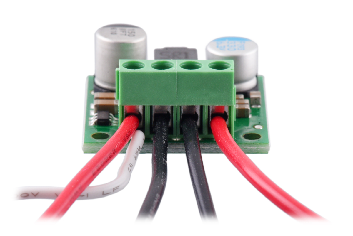
The regulator includes a 5×1 straight male header strip and two 2-pin, 3.5 mm-pitch terminal blocks, and it can be assembled with either the header or terminal blocks, not both. The 0.1" male header can be soldered into the smaller through-holes. Alternatively, the terminal blocks can be locked together and soldered into the larger holes to allow for convenient temporary connections of unterminated wires (see Pololu's short video on terminal block installation). You can also solder wires directly to the board for the most compact installation.
|
|

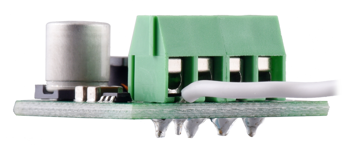
If the terminal blocks are used, a small wire (not included) can be soldered to the enable pin as shown below, so it will not interfere with the VIN terminal block connection.
|
|
Typical efficiency
The efficiency of a voltage regulator, defined as (Power out)/(Power in), is an important measure of its performance, especially when battery life or heat are concerns.
 |
Maximum continuous output current
The maximum achievable output current of the regulator varies with the input voltage but also depends on other factors, including the ambient temperature, air flow, and heat sinking. The graph below shows maximum output currents that the regulators in the S13VxF5 family can deliver continuously at room temperature in still air and without additional heat sinking.
 |
During normal operation, this product can get hot enough to burn you. Take care when handling this product or other components connected to it.
Quiescent current
The quiescent current is the current the regulator uses just to power itself, and the graph below shows this as a function of the input voltage. The module’s EN input can be driven low to put the board into a low-power state where it typically draws between 2 µA and 10 µA per volt on VIN.
 |
Typically the quiescent current of the S13V30F5 is below 20 mA, but for input voltages between about 3 V and 3.3 V the quiescent current of some units can rise to near 100 mA. Keeping connections short and adding a capacitor of a few tens of microfarads greatly reduces this spike in quiescent current.
People often buy this product together with:
 |
Pololu 3.3V Step-Up/Step-Down Voltage Regulator S7V8F3 |
Dimensions
| Size: | 0.9" × 0.9" × 0.38"1 |
|---|---|
| Weight: | 3.5 g2 |
General specifications
| Minimum operating voltage: | 2.8 V |
|---|---|
| Maximum operating voltage: | 22 V |
| Continuous output current: | 3 A3 |
| Output voltage: | 5 V |
| Reverse voltage protection?: | Y4 |
| Maximum quiescent current: | 100 mA5 |
| Output type: | fixed 5V |
Identifying markings
| PCB dev codes: | reg26a |
|---|---|
| Other PCB markings: | 0J12777 |
Notes:
- 1
- Without included optional headers or terminal blocks. Height with terminal blocks installed is approximately 0.5".
- 2
- Without included optional headers or terminal blocks.
- 3
- Typical continuous output current at 5 V in. Actual achievable continuous output current is a function of input voltage and is limited by thermal dissipation. See the output current graph under the description tab for more information.
- 4
- To -20 V. Connecting supplies over 20 V in reverse can damage the device.
- 5
- While enabled with no load. Typically the quiescent current is much lower (under 20 mV). See the quiescent current graph under the description tab for more information. Can be reduced to under 1 mA using the enable pin.
File downloads
-
Dimension diagram of the 5V Step-Up/Step-Down Voltage Regulator S13V30F5 (294k pdf)
-
3D model of the 5V Step-Up/Step-Down Voltage Regulator S13V30F5 (5MB step)
-
Drill guide for the 5V Step-Up/Step-Down Voltage Regulator S13V30F5 (41k dxf)
This DXF drawing shows the locations of all of the board’s holes.
Exact shipping can be calculated on the view cart page (no login required).
Products that weigh more than 0.5 KG may cost more than what's shown (for example, test equipment, machines, >500mL liquids, etc).
We deliver Australia-wide with these options (depends on the final destination - you can get a quote on the view cart page):
- $3+ for Stamped Mail (typically 10+ business days, not tracked, only available on selected small items)
- $7+ for Standard Post (typically 6+ business days, tracked)
- $11+ for Express Post (typically 2+ business days, tracked)
- Pickup - Free! Only available to customers who live in the Newcastle region (must order online and only pickup after we email to notify you the order is ready). Orders placed after 2PM may not be ready until the following business day.
Non-metro addresses in WA, NT, SA & TAS can take 2+ days in addition to the above information.
Some batteries (such as LiPo) can't be shipped by Air. During checkout, Express Post and International Methods will not be an option if you have that type of battery in your shopping cart.
International Orders - the following rates are for New Zealand and will vary for other countries:
- $12+ for Pack and Track (3+ days, tracked)
- $16+ for Express International (2-5 days, tracked)
If you order lots of gear, the postage amount will increase based on the weight of your order.
Our physical address (here's a PDF which includes other key business details):
40 Aruma Place
Cardiff
NSW, 2285
Australia
Take a look at our customer service page if you have other questions such as "do we do purchase orders" (yes!) or "are prices GST inclusive" (yes they are!). We're here to help - get in touch with us to talk shop.
Have a product question? We're here to help!
 Pololu 5V, 5A Step-Down Voltage Regulator D24V50F5SKU: POLOLU-2851 Brand: PololuThis small synchronous switching step-down (or buck) regulator takes an input vo ...
- Polymer Lithium Ion Battery (LiPo) 3.7V 2400mAhSKU: CE04379 Brand: Core Electronics
Welcome to the awesomeness that is LiPo batteries. Polymer Lithium Ion batter ...
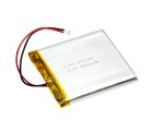
- Polymer Lithium Ion Battery (LiPo) 3.7V 4400mAhSKU: CE04380 Brand: Core ElectronicsThis Lithium Polymer Ion based battery is a slim, lightweight battery that is pe ...
- Raspberry Pi UPS HATSKU: DFR0494 Brand: DFRobotDFRobot Raspberry Pi UPS HAT is an uninterruptable power supply shield for Raspb ...


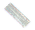
- Solderless Breadboard - 830 Tie Point (ZY-102)SKU: CE00304 Brand: Core ElectronicsIf you're prototyping a circuit big or small, then you'll want a quality breadbo ...
- Nano V3.0 BoardSKU: CE05101 Brand: Core ElectronicsThe Nano V3.0 is compatible with the Arduino Nano V3.0. This is a small, complet ...
- JST-PH 2 Pin Female ConnectorSKU: FIT0148 Brand: DFRobotThis product includes 2-pin 2.0mm mating connector housing(10 units) and crimp p ...
- JST-PH 3 Holes Female ConnectorSKU: FIT0149 Brand: DFRobotThis product includes 3-pin 2.0mm mating connector housing(10 units) and crimp p ...


Videos
View AllGuides

PiicoDev Magnetometer- Getting Started Guide

The Maker Revolution

How to Use DC Regulators/Converters

Powering Portable Projects: Batteries
Projects

Wireless QI Phone Charger Powered by Raspberry Pi

mmPi-Pico HAT

Solar Charging Station

Makers love reviews as much as you do, please follow this link to review the products you have purchased.
Product Comments