
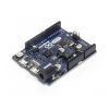


Arduino Zero
In stock, ships same business day if ordered before 2PM
Fastest delivery: Tomorrow*
Disclaimer:
For next-day delivery, the shipping address must
be in the AusPost next-day network, eParcel Express must be selected, and the order must be placed
before 2PM AEST Mon-Thurs excluding NSW Public Holidays. Orders may be delayed due to AusPost
pickup timings and order verifications. eParcel Express is typically a 1-day service within the
AusPost next-day network, though it is sometimes 2+ days.
Quantity Discounts:
- 25+ $82.39 (exc GST)
- 100+ $78.05 (exc GST)
Recommended Essentials:
")
The Zero is a simple and powerful 32-bit extension of the platform established by the UNO. The Zero board expands the family by providing increased performance, enabling a variety of project opportunities for devices, and acts as a great educational tool for learning about 32-bit application development. The Zero applications span from smart IoT devices, wearable technology, high-tech automation, to crazy robotics. The board is powered by Atmel’s SAMD21 MCU, which features a 32-bit ARM Cortex® M0+ core. One of its most important features is Atmel’s Embedded Debugger (EDBG), which provides a full debug interface without the need for additional hardware, significantly increasing the ease-of-use for software debugging. EDBG also supports a virtual COM port that can be used for device and bootloader programming.
Warning: Unlike most Arduino & Genuino boards, the Zero runs at 3.3V. The maximum voltage that the I/O pins can tolerate is 3.3V. Applying voltages higher than 3.3V to any I/O pin could damage the board.
The board contains everything needed to support the microcontroller; simply connect it to a computer with a micro-USB cable or power it with a AC-to-DC adapter or battery to get started. The Zero is compatible with all the shields that work at 3.3V and are compliant with the 1.0 Arduino pinout.
You can find your board warranty information here.
Note: Arduino and Genuino boards based on AVR microcontrollers get a reset and restart sketch execution each time the Serial Monitor of the Arduino Software (IDE) is opened. This is also the mechanism used to upload sketches to these boards. This board is different: when the Zero is connected through the Programming Port and you open the Serial Monitor, the board does not automatically reset and the sketch loaded keeps running. To restart the sketch you need to press the reset button on the board itself.
Getting Started
In the Getting Started section, you can find all the information you need to configure your board, use the Arduino Software (IDE), and start to tinker with coding and electronics. To keep your Zero's Bootloader up to date, the Update Procedure explains what you should do each time there is a new Arduino SAMD Boards release.
Technical Specifications
- Microcontroller: ATSAMD21G18, 32-Bit ARM Cortex M0+
- Operating Voltage: 3.3V
- Digital I/O Pins: 20
- PWM Pins: All but pins 2 and 7
- UART: 2 (Native and Programming)
- Analog Input Pins: 6, 12-bit ADC channels
- Analog Output Pins: 1, 10-bit DAC
- External Interrupts: All pins except pin 4
- DC Current per I/O Pin: 7 mA
- Flash Memory: 256 KB
- SRAM: 32 KB
- EEPROM: None. See documentation
- LED_BUILTIN: 13
- Clock Speed: 48 MHz
- Length: 68 mm
- Width: 53 mm
- Weight: 12 gr
OSH: Schematics
The Zero is open-source hardware! You can build your own board using the following files:
Pinout Diagram

ARM Core Benefits
The Zero has a 32-bit ARM core that can outperform typical 8-bit microcontroller boards. The most significant differences are:
- 32-bit core that allows operations on 4 byte wide data within a single CPU clock. (For more information see the int type page)
- CPU Clock at 48MHz
- 12 channels DMA controller that can relieve the CPU from doing memory intensive tasks
- 32 bit Real Time Counter (RTC) with clock/calendar function
- 32 bit CRC generator
- Two-channel Inter IC Sound (I2S) interface
- Peripheral Touch Controller (PTC)
For further information about the SAM-D21 microcontroller please refer to the datasheet.
Atmel Embedded Debugger
The Atmel Embedded Debugger (EDBG) implements a SWD interface in order to program the on-board SAMD21 and is also connected to one hardware serial of the microcontroller. This means that the 'Serial' class responds to the programming port of the board. The Zero has been designed in collaboration with ATMEL, and the on-board EDBG can be used through ATMEL Studio to get full access to the microcontroller memories to help debug your code.
Power
The Arduino Zero can be powered via the USB connector or with an external power supply. The power source is selected automatically.
External (non-USB) power can come either from an AC-to-DC adapter (such as a wall-wart) or battery, and can be connected using a 2.1mm center-positive plug connected to the board's power jack, or directly to the GND and VIN pin headers of the POWER connector.
The board can operate on an external supply of 6 to 20 volts. The recommended range is 7 to 12 volts.
The power pins are as follows:
- VIN. The input voltage to the board when it's using an external power source (as opposed to 5 volts from the USB connection or other regulated power source). You can supply voltage through this pin, or if supplying voltage via the power jack, access it through this pin.
- 5V. This pin outputs a regulated 5V from the regulator on the board. The board can be supplied with power either from the DC power jack (7 - 12V), the USB connector (5V), or the VIN pin of the board (7-12V). Supplying voltage via the 5V or 3.3V pins bypasses the regulator, and can damage your board if it is not sufficiently regulated. We don't advise it.
- 3.3V. A 3.3 volt supply generated by the on-board regulator. Maximum current draw is 800 mA. This regulator also provides power to the SAMD21 microcontroller.
- GND. Ground pins.
- IOREF. This pin on the board provides the voltage reference with which the microcontroller operates. A properly configured shield can read the IOREF pin voltage and select the appropriate power source or enable voltage translators on the outputs for working with the 5V or 3.3V.
Memory
The SAMD21 has 256 KB Flash Memory. It also has 32 KB of SRAM and up to 16 KB of EEPROM by emulation.
Input and Output
Each of the 20 general purpose I/O pins on the Zero can be used for digital input or digital output using pinMode(), digitalWrite(), and digitalRead() functions. Pins that can be used for PWM output are: 3, 4, 5, 6, 8, 9, 10, 11, 12, 13 using analogWrite() function. All pins operate at 3.3 volts. Each pin can source or sink a maximum of 7 mA and has an internal pull-up resistor (disconnected by default) of 20-50 kOhms.
In addition, some pins have specialized functions
- Serial: 0 (RX) and 1 (TX). Used to receive (RX) and transmit (TX) TTL serial data. These pins are connected to the Serial1 class. The native usb port instead responds to the SerialUSB class
- External Interrupts: available on all the pins except pin 4.
- DAC: A0. Provide a 10bit voltage output with the analogWrite() function.
- PWM: 3, 4, 5, 6, 8, 9, 10, 11, 12, 13. Provide 8-bit PWM output with the analogWrite() function.
- SPI: SS, MOSI, MISO, SCK. Located on the ICSP header only support SPI communication using the SPI library.
- LED: 13. There is a built-in LED driven by digital pin 13. When the pin is HIGH value, the LED is on, when the pin is LOW, it's off.
- Analog Inputs. Six of the 20 general purpose I/O pins on the Zero provide analog input. These are labeled A0 through A5, and each provide up to 12bits of resolution (i.e. 4096 different values). By default they measure from ground to 3.3 volts, though is it possible to change the upper end of their range using the AREF pin and the analogReference() function.
- TWI: SDA pin and SCL pin. Support TWI communication using the Wire library
There are a couple of other pins on the board:
- AREF. Reference voltage for the analog inputs. Used with analogReference().
- Reset. Bring this line LOW to reset the microcontroller. Typically used to add a reset button to shields which block the one on the board.
Programming
Uploading sketches to the SAMD21 is different from the AVR microcontrollers found in other Arduino & Genuino boards.
Either USB port can be used for programming the board, although using the Programming port is recommended due to the way the erasing of the chip is handled:
- Programming port: To use this port, select "Arduino/Genuino Zero (Programming Port)" as your board in the Arduino IDE. Connect the Zero's programming port (the one closest to the DC power jack) to your computer. The programming port uses the EDBG as a USB-to-SWD chip.
- Native port: To use this port, select "Arduino/Genuino Zero (Native USB Port)" as your board in the Arduino IDE. The Native USB port is connected directly to the SAMD21. Connect the Zero's Native USB port (the one closest to the reset button) to your computer.
Unlike other Arduino & Genuino boards which use avrdude for uploading, the Zero relies on bossac while the programming port uses openOCD.
JTAG connector for debugging through SWD
Another external debugger can be used by means of the on-board JTAG connector.
ICSP Connector used for SPI communication
Here are details of the SPI pins location within the ICSP connector:
EEPROM
Part of the Flash memory may be used as a non-volatile storage with some limitations, the lifetime of the typical flash memory is about 25K write-cycles, and unlike EEPROM, and it must be erased in pages before writing. The flash memory is erased when you upload a new sketch.
Serial ports
- Serial is a hardware serial port internally connected to the EDBG chip and corresponds to the virtual serial port on your computer when you connect the Arduino Zero through the programming USB connector;
- SerialUSB is a virtual USB serial port, which corresponds to the virtual serial port on your computer when you connect the Arduino Zero through the native USB connector.
- Serial1 is the hardware serial port connected to pin 0 and 1, which is free to use to connect to external serial devices.
Burn the Bootloader
Using the Zero Programming Port it is possible to burn the bootloader used by the Native USB port. To burn the bootloader follow this procedure:
- select Tools->Programmer->Atmel EDBG
- select Tools->Board->Arduino/Genuino Zero (Programming Port)
- select Tools->Burn Bootloader
USB Overcurrent Protection
The Zero has a resettable polyfuse that protects your computer's USB ports from shorts and overcurrent. Although most computers provide their own internal protection, the fuse provides an extra layer of protection. If more than 500 mA is applied to the USB port, the fuse will automatically break the connection until the short or overload is removed.
Physical Characteristics
The maximum length and width of the Zero PCB are 2.7 and 2.1 inches respectively, with the USB connectors and power jack extending beyond the former dimension. Three screw holes allow the board to be attached to a surface or case. Note that the distance between digital pins 7 and 8 is 160 mil (0.16"), not an even multiple of the 100 mil spacing of the other pins. The Zero is designed to be compatible with most shields designed for the Uno, Diecimila or Duemilanove. Digital pins 0 to 13 (and the adjacent AREF and GND pins), analog inputs 0 to 5, the power header, and "ICSP" (SPI) header are all in equivalent locations. Further the main UART (serial port) is located on the same pins (0 and 1).
Exact shipping can be calculated on the view cart page (no login required).
Products that weigh more than 0.5 KG may cost more than what's shown (for example, test equipment, machines, >500mL liquids, etc).
We deliver Australia-wide with these options (depends on the final destination - you can get a quote on the view cart page):
- $3+ for Stamped Mail (typically 10+ business days, not tracked, only available on selected small items)
- $7+ for Standard Post (typically 6+ business days, tracked)
- $11+ for Express Post (typically 2+ business days, tracked)
- Pickup - Free! Only available to customers who live in the Newcastle region (must order online and only pickup after we email to notify you the order is ready). Orders placed after 2PM may not be ready until the following business day.
Non-metro addresses in WA, NT, SA & TAS can take 2+ days in addition to the above information.
Some batteries (such as LiPo) can't be shipped by Air. During checkout, Express Post and International Methods will not be an option if you have that type of battery in your shopping cart.
International Orders - the following rates are for New Zealand and will vary for other countries:
- $12+ for Pack and Track (3+ days, tracked)
- $16+ for Express International (2-5 days, tracked)
If you order lots of gear, the postage amount will increase based on the weight of your order.
Our physical address (here's a PDF which includes other key business details):
40 Aruma Place
Cardiff
NSW, 2285
Australia
Take a look at our customer service page if you have other questions such as "do we do purchase orders" (yes!) or "are prices GST inclusive" (yes they are!). We're here to help - get in touch with us to talk shop.
Have a product question? We're here to help!
 3pc Heatsink Kit for Raspberry PiSKU: CE05645 Brand: Core ElectronicsA low-cost pack of heat sinks that are perfectly sized for the Raspberry Pi. Att ...
- Raspberry Pi 3+ Power Supply (Official)SKU: CE00278 Brand: Raspberry PiThe Raspberry Pi 3 Model B is the most power hungry platform released to-date an ...
- Raspberry Pi USB Power Cable with Switch (Power Only, Pi 2/3/3B/3B+)SKU: CE04443 Brand: Core ElectronicsThis handy little guy is a standard microUSB cable with an inline switch which a ...
- Micro B USB In-line Power Switch Cable (Female to Male)SKU: CE04814 Brand: Core ElectronicsUnplugging USB devices just to remove power is a thing of the past with this han ...


- Adafruit I2S MEMS Microphone Breakout - SPH0645LM4HSKU: ADA3421 Brand: AdafruitListen to this good news - Adafruit now have a breakout board for a super tiny I ...

Videos
View AllGuides

Arduino Uno Q Explained | A Hybrid Linux and Microcontroller Dev Board

How to Reinstall Linux on the Uno Q | Arduino Reflashing Guide

Getting Started with the Arduino Uno Q

How to Control a Water Pump with an Arduino
Projects

IR Break-Beam Stopwatch

Coffee Grinder With Arduino

The Hipster Coaster
Educational Workshops

Arduino Workshop for Beginners

Makers love reviews as much as you do, please follow this link to review the products you have purchased.
Product Comments