Welcome to the Arduino Workshop, where you'll be able to follow our guided course which covers everything you'll need to know in order to create your own Arduino projects and become a leveled up maker. My name is Sam and along with being a maker myself, I also enjoy teaching others how to use different technology and create amazing projects. Along with the course videos themselves, you can find all of the related course material such as code examples, circuit diagrams, images, and other resources.
We'll be working with Arduino so you'll need an Arduino board to follow this course. We'll be introducing many different concepts including working with various types of hardware such as sensors, displays, and general electronics components, and the kit we're using for all of this is the Sparkfun Inventors Kit. If you are not in Australia, you can grab from Sparkfun directly and have it shipped to you almost anywhere in the world.
Course Goals:
- Understand what an Arduino is and how it works
- Learn how to use an Arduino safely
- Program your Arduino using code that you've written in the Arduino IDE (Integrated Development Environment)
- Learn programming concepts using C and C++ along with Arduino specific programming
- Understand best practice concepts for programming and prototyping
- Use a wide variety of hardware and components and prototype your projects using a breadboard
- Build your own innovative project with Arduino
When you're ready, let's begin the Arduino Workshop!
If you run into any issues throughout this workshop, then please reach out to us on our forum. We're full-time makers and are here to help.
Chapter 1: Introduction to Arduino
1.0 Chapter Overview
In this chapter you'll learn about:
- What is Arduino
- Different types of Arduino boards
- How does the Arduino Uno board work and why it's so popular
- What is a microcontroller
- How to use the Arduino IDE (Integrated Development Environment)
- Powering and connecting your Arduino to your computer
- Uploading programs to your Arduino board
By the end of this chapter, you will have uploaded your first program to your Arduino board to control an LED.
1.1 What is Arduino?
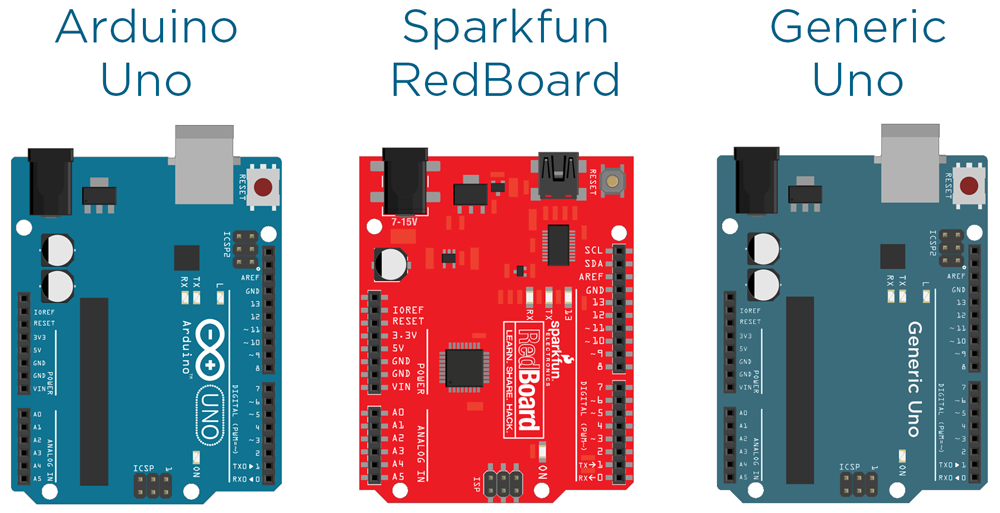
In this section, we look at what is Arduino, what it's good for makers, and some of the different types of Arduino boards available.
Section Resources:
Example Arduino Uno Variations
1.2 What is a Microcontroller?
In this section, we'll be looking at what is a microcontroller (the chip at the heart of any Arduino board), an overview of how they work, and how it integrates with the Arduino environment.
1.3 The Arduino Uno
In this section, you'll learn about the features and capabilities of the Arduino Uno board, how the layout of the board can affect your project, and why the Uno is such a great all-rounder.
1.4 Arduino IDE and the Language
In this section, we'll take a look at the Arduino IDE, which is where you write the code for your Arduino, upload it, and communicate with your board. We'll also cover the programming language that Arduino IDE uses, and where to download it.
Section Resources:
- You can download the Arduino IDE from the Arduino website.
1.5 Powering and Connecting Your Arduino
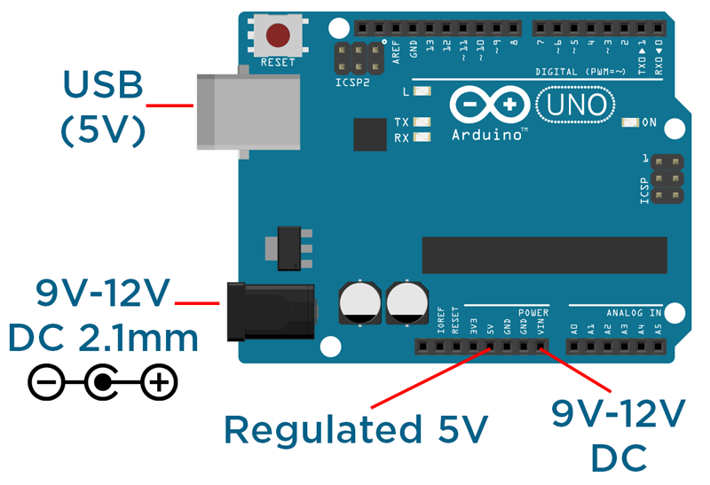
In this section, you'll be learning about the various ways to power your Arduino, and how to connect it up to your computer for uploading your programs, and communicating to the computer using the serial port.
Section Resources:
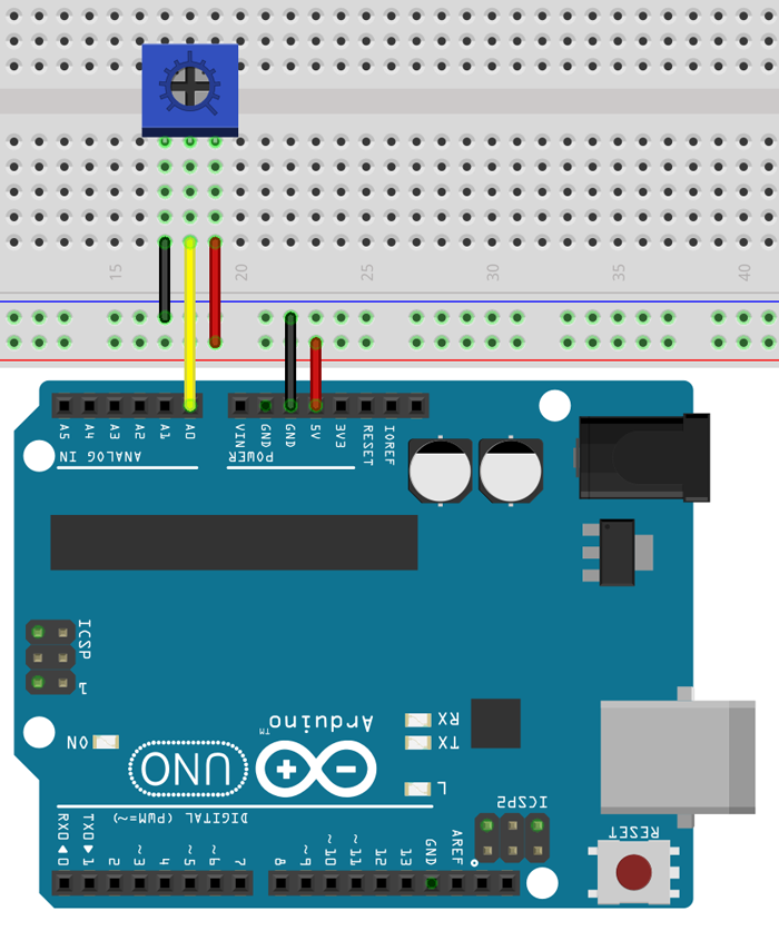
Arduino Power Layout
1.6 Hello World Example
In the final section of this chapter, we'll talk through using the Arduino IDE to upload your first program to your Arduino board.
Section Resources:
Source code for 'Hello World'
void setup() {
  pinMode(13, OUTPUT);       //setup pin 13 as an output
}

void loop() {
  digitalWrite(13, HIGH);    // turn the LED on (HIGH outputs 5V)
  delay(500);                 // wait for 500 milliseconds
  digitalWrite(13, LOW);     // turn the LED off (LOW outputs 0V)
  delay(500);                 // wait for 500 milliseconds
}
Chapter 2: Using Inputs and Outputs
2.0 Chapter Overview
In this chapter you'll learn about:
- How to properly structure your code
- Using variables to write more capable programs
- Building circuits using a breadboard
- Reading inputs and controlling outputs using the digital and analog pins
- Communicating via the serial port
By the end of the chapter, you will have created an input interface for your Arduino, using the Serial Monitor to display the data.
2.1 Program Structure
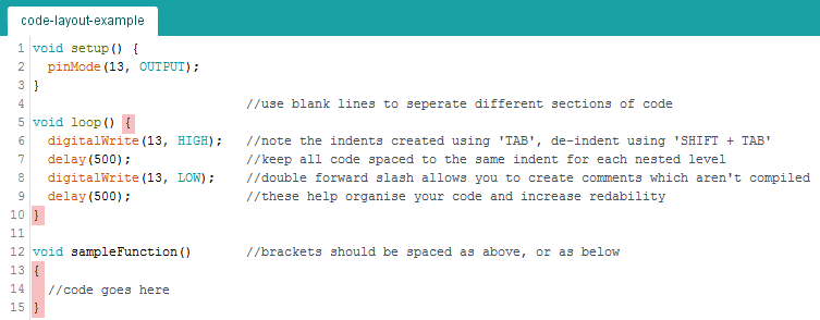
In this section, we'll be learning about how to properly structure code using indentations, nested levels, and semicolons.
Section Resources:
Example Program Structure
2.2 Using Variables
In this section, we'll explore the use of variables, which will allow you to write more sophisticated code.
Section Resources:
Arduino Reference Datatypes:
If you're interested in learning more about the various datatypes that Arduino supports, check out the reference page.
2.3 Building Your First Circuit Using a Breadboard
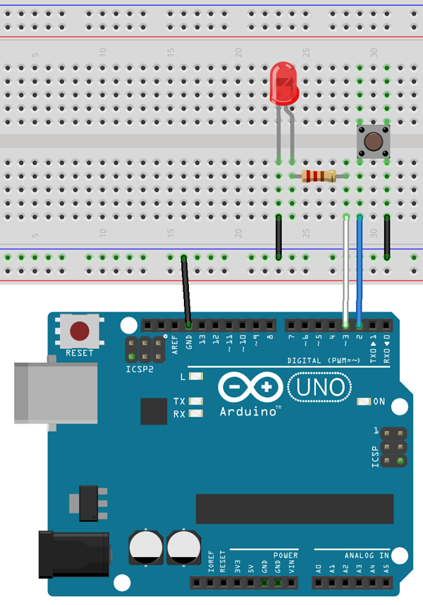
In this section, we'll look at using different components such as LEDs, buttons, jumper wires, resistors, and a breadboard to construct a circuit.
Section Resources:
Further Reading
If you'd like to know more about how electronic components work, check out the Analogue Electronics Crash Course and All About LEDs tutorials for more in-depth information.
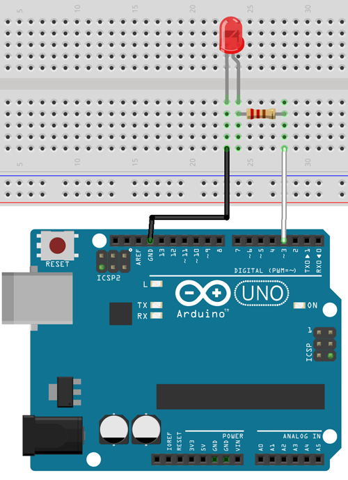
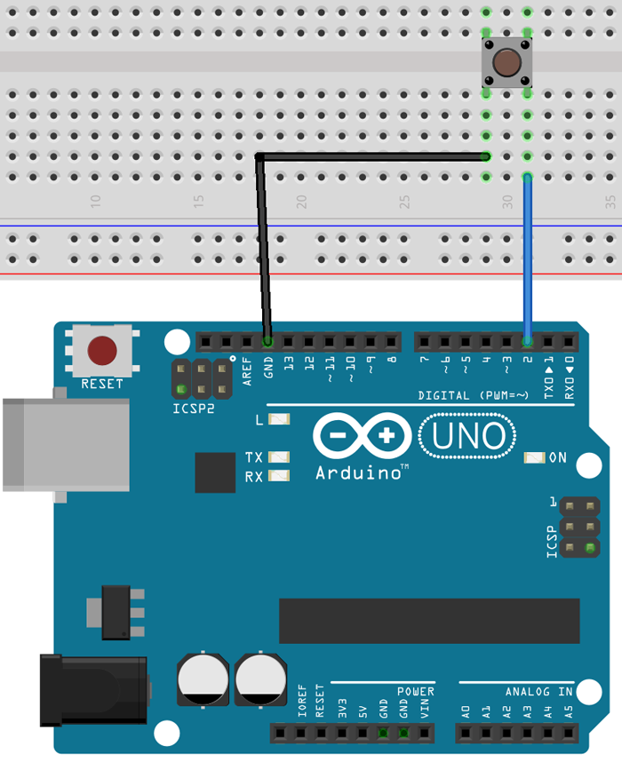
Wiring Diagram
2.4 Using Digital Pins
In this section, we'll learn how to use the digital pins to read inputs and control outputs.
Section Resources:
Source code for 'LED Button'
int buttonPin = 2;
int ledPin = 3;

void setup() {
  // setup pin modes
  pinMode(ledPin, OUTPUT);
  pinMode(buttonPin, INPUT_PULLUP);
}

void loop() {
  // read state of buttonPin and store it as the buttonState variable
  int buttonState = digitalRead(buttonPin);
  // write the value of buttonState to ledPin
  digitalWrite(ledPin, buttonState);
}
Wiring Diagram for 'Digital Pins'
2.5 Using Analogue Pins
In this section, we'll learn how to use the analog pins to read inputs and control outputs.
Section Resources:
Source Code for 'Blink Rate Control'
int ledPin = 3;
int potPin = A0;

void setup() {
  // setup pin modes
  pinMode(ledPin, OUTPUT);
  pinMode(potPin, INPUT);
}

void loop() {
  // read the value of the pot and store it as potValue
  int potValue = analogRead(potPin);

  // turn led on and wait for the time equal to potValue
  digitalWrite(ledPin, HIGH);
  delay(potValue);

  // re-read the value of the pot and store it as potValue
  potValue = analogRead(potPin);

  // turn led off and wait for the time equal to potValue
  digitalWrite(ledPin, LOW);
  delay(potValue);
}
Source Code for 'LED Brightness Control'
int ledPin = 3;
int potPin = A0;

void setup() {
  // setup pin modes
  pinMode(ledPin, OUTPUT);
  pinMode(potPin, INPUT);
}

void loop() {
  // read the value of the pot, divide it by 4, and store it as potValue
  int potValue = analogRead(potPin) / 4;

  // turn led on with the value of potValue
  analogWrite(ledPin, potValue);
}
Wiring Diagram for 'Analogue Pins'
2.6 Displaying Information Using the Serial Port
In this section, we'll be looking at using the serial port on the Arduino to communicate with a computer via USB.
Section Resources:
Source Code for 'Serial Monitoring'
int ledPin = 3;
int buttonPin = 2;
int potPin = A0;

void setup() {
  // setup pin modes
  pinMode(ledPin, OUTPUT);
  pinMode(buttonPin, INPUT_PULLUP);
  pinMode(potPin, INPUT);

  // initialise serial port with baud rate of 9600
  Serial.begin(9600);
}

void loop() {
  // read the state of buttonPin and store it as buttonState (0 or 1)
  int buttonState = digitalRead(buttonPin);

  // read the value of the pot, divide it by 4, and store it as potValue
  int potValue = analogRead(potPin);
  int filteredPotValue = potValue / 4;

  // turn led on with the value of potValue
  analogWrite(ledPin,filteredPotValue);

  // print the value of the button
  Serial.print("Button: ");
  Serial.print(buttonState);
  Serial.print("   ");

  // print the value of the pot
  Serial.print("Pot: ");
  Serial.print(potValue);
  Serial.print("   ");

  // print the value of the pot / 4 with a line return at the end
  Serial.print("Pot/4: ");
  Serial.println(filteredPotValue);
}
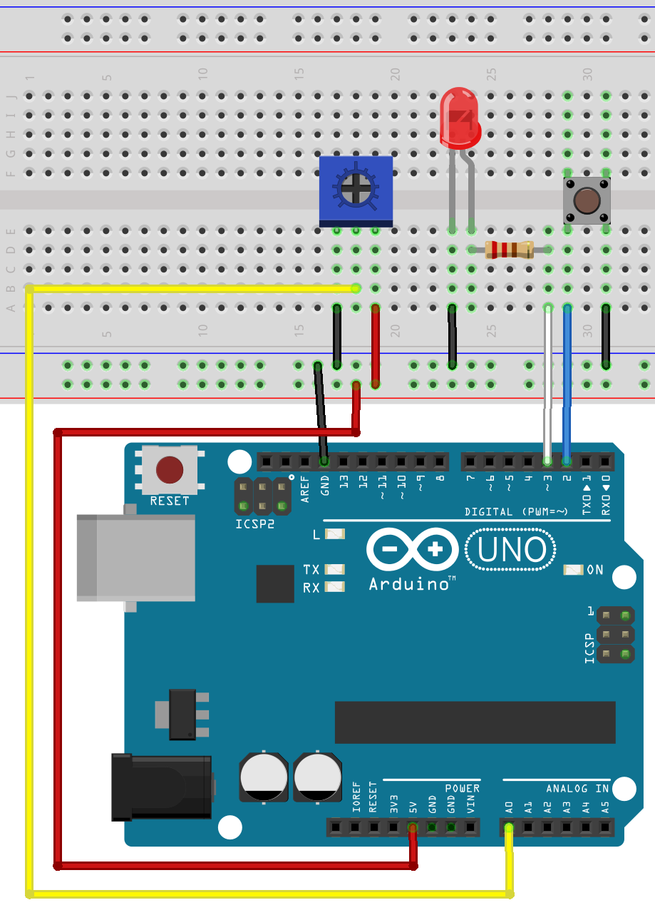
Wiring Diagram for 'Serial Reading'
Chapter 3: Decision Making and Using Logic
3.0 Chapter Overview
In this chapter you'll learn about:
- Using 'If' statements
- Using 'while' loops
- Using 'for' loops
- Using 'Switch cases'
- Using maths in Arduino
- Creating functions
- Creating sophisticated code
By the end of this chapter, you will have created your very own calculator using different functions, loops, and Serial functions.
3.1 'If' Statements
In this section, we'll be looking at using 'If' statements, which are the backbone of decision-making for microcontrollers.
Section Resources:
Source Code for 'Toggle Switch'
// pin definitions
int ledPin = 3;
int buttonPin = 2;

// global variables
int toggleState;
int lastButtonState = 1;
long unsigned int lastPress;
int debounceTime = 20;

void setup() {
  // setup pin modes
  pinMode(ledPin, OUTPUT);
  pinMode(buttonPin, INPUT_PULLUP);
}

void loop() {
  int buttonState = digitalRead(buttonPin);   //read the state of buttonPin and store it as buttonState (0 or 1)

  if((millis() - lastPress) > debounceTime)   //if the time between the last buttonChange is greater than the debounceTime
  {
    lastPress = millis();   //update lastPress
    if(buttonState == 0 && lastButtonState == 1)    //if button is pressed and was released last change
    {
      toggleState =! toggleState;                 //toggle the LED state
      digitalWrite(ledPin, toggleState);
      lastButtonState = 0;    //record the lastButtonState
    }

    if(buttonState == 1 && lastButtonState == 0)    //if button is not pressed, and was pressed last change
    {
      lastButtonState = 1;    //record the lastButtonState
    }
  }
}
Wiring Diagram for 'Digital Pins'
3.2 'While' Loops
In this section, you'll learn about using 'while' loops and how to use them to change the structure of your code.
Section Resources:
Source Code for 'LED Flash Rate'
// pin definitions
int ledPin = 3;
int buttonPin = 2;

// global variables
int toggleState;
int buttonState =1;

void setup() {
  // setup pin modes
  pinMode(ledPin, OUTPUT);
  pinMode(buttonPin, INPUT_PULLUP);
}

void loop() {
  buttonState = digitalRead(buttonPin);

  while(buttonState == 0)
  {
    toggleState =! toggleState;
    digitalWrite(ledPin, toggleState);
    delay(50);
    buttonState = digitalRead(buttonPin);
  }

  toggleState =! toggleState;
  digitalWrite(ledPin, toggleState);
  delay(200);
}
Wiring Diagram for 'LED Flash Rate'
3.3 'For' Loops
In this section, you'll look at 'for' loops which you can use to control the flow of your program.
Section Resources:
Source Code for 'LED Pulse'
// pin definitions
int ledPin = 3;

// global variables
int rampTime = 2;

void setup() {
  // setup pin modes
  pinMode(ledPin, OUTPUT);
  //initialise serial port
  Serial.begin(9600);
}

void loop() {
  // ramp LED brightness up to max
  for(int i = 0; i<256; i++)
  {
    analogWrite(ledPin, i);
    delay(rampTime);
    Serial.println(i);
  }

  // ramp LED brightness down to 0
  for(int i = 255; i>0; i--)
  {
    analogWrite(ledPin, i);
    delay(rampTime);
    Serial.println(i);
  }
}
Wiring Diagram for 'LED Pulse'
3.4 Using 'Switch' Cases
In this section, we'll dive into using 'switch' cases to implement comparative lists and outcomes.
Section Resources:
Source Code for 'Potentiometer Switch Case'
// pin definitions
int potPin = A0;

// declare global variables
int lastPotValue;

void setup() {
  // set pin modes
  pinMode(potPin, INPUT);
  //initialise Serial port
  Serial.begin(9600);
}

void loop() {
  // read potPin and divide by 255 to give 5 possible readings
  int potValue = analogRead(potPin) / 255;

  // if something has changed since last value
  if(potValue != lastPotValue)
  {
    // enter switch case
    switch(potValue)
    {
      case 0:
        Serial.println("Very Low");
        break;
      case 1:
        Serial.println("Low");
        break;
      case 2:
        Serial.println("Moderate");
        break;
      case 3:
        Serial.println("High");
        break;
      case 4:
        Serial.println("Extreme");
        break;
      default:
        Serial.println("error!");
        break;
    }
    lastPotValue = potValue;
  }
}
Wiring Diagram for 'Potentiometer Switch Case'
3.5 Using Maths
In this section, we'll look at how to use different mathematic functions and methods in Arduino.
Section Resources:
Example for 'Maths Functions'
x = y + 3;
x = y - 7;
x = y * 6;
x = y / 4;
3.6 Creating Functions
In this section, we'll be learning about using and creating your own functions to write modular, reusable code.
Section Resources:
Source Code for 'Hypotenuse Calculator'
*Update 8/1/18: I've updated the sketch for the hypotenuse calculater which is reflected in the code below. It provides rejection for non-integer values and some extra feedback.
void setup() {
  //initialise Serial port
  Serial.begin(9600);
}

void loop() {
  int a;
  int b;
  float result;

  //print instructions, and wait until there is something in the serial buffer
  Serial.print("Enter a side value: ");
  while(!Serial.available());
  a = readSerial();
    if(a == 0)
    {
      return;
    }
  Serial.print("Enter the other side value: ");
  while(!Serial.available());
  b = readSerial();
    if(b == 0)
    {
      return;
    }
  findSide(a,b);

  Serial.println();
}

//readSerial takes the next integer in the Serial buffer, clears the buffer, then returns it
int readSerial()
{
  int i = Serial.parseInt();

  //checks if the received value is a valid integer
  if(i < 1 || (i%1 != 0))
  {
    Serial.println("That isn't a valid integer");
    return 0;
  }
  Serial.println(i);
  Serial.parseInt();
  return i;
}

void findSide(int x, int y)
{
  //calculate C squared by A squared + B squared
  float hypotenuse = sqrt(x*x + y*y);

  //print out the result
  Serial.print("Hypotenuse = ");
  Serial.println(hypotenuse);
}
Chapter 4: Data Manipulation and EEPROM
4.0 Chapter Overview
In this chapter you'll learn about:
- Using variables within Arrays
- Using arithmetic, relational, logical, and assignment operators
- Manipulating data using bit-wise operators and logic
- Storing information between resets using EEPROM
By the end of this chapter, you will have created an LED sequencing display using arrays, operators, and EEPROM storage.
4.1 Arrays
In this section, we'll look at using arrays to store data, which allows for more powerful variable manipulation.
Section Resources:
Source Code for 'LED Sequencer'
int ledArray[] = {2,3,4,5,6,7,8,9};

int delayTime = 50;

void setup() {
  //initialise ledArray as outputs
  for(int i = 0; i<10; i++)
  {
    pinMode(ledArray[i], OUTPUT);
  }
}

void loop() {
  //turn LEDs on from 0-7
  for(int i = 0; i <= 7; i++)
  {
    digitalWrite(ledArray[i], HIGH);
    delay(delayTime);
  }

  //turn LEDs off from 7-0
  for(int i = 7; i >= 0; i--)
  {
    digitalWrite(ledArray[i], LOW);
    delay(delayTime*5);
  }
}
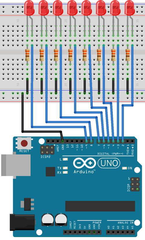
Wiring Diagram
4.2 Operators
In this section, we're going to look at using arithmetic, relational, logical, and assignment operators. These are all used for comparing and evaluating data.
Section Resources:
Relation Operators Reference
x = 4
y = 6

(x == y)  false
(x != y)  true
(x > y)   false
(x < y)   true
(x >= y)  false
(x <= y)  true
Logical Operators
x = 0
y = 1

(x && y)  false
(x || y)  true
 x = !x   x now equals 1 (not 0)
Assignment Operators
i += 2  same as i = i+2
i -= 2  same as i = i-2
i *= 2  same as i = i*2
i /= 2  same as i = i/2
4.3 Bit Math
In this section, you'll be learning about control individual bits within bytes using bit-wise operators and logic.
Section Resources:
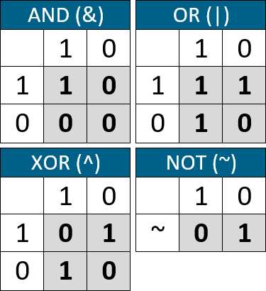
Bitwise Operator Examples
/*This section is a logic reference example.
This is not valid code and won't compile on your Arduino
//AND
    x = 0011 0100
    y = 0101 1101
x & y = 0001 0100

//OR
    x = 0011 0100
    y = 0101 1101
x | y = 0111 1101

//XOR
    x = 0011 0100
    y = 0101 1101
x ^ y = 0110 1001

//NOT
 x = 0011 0100
~x = 1100 1011
 y = 0101 1101
~y = 1010 0010

//SHIFT LEFT
     x = 0011 0100
x << 2 = 1101 0000
     y = 0101 1101
y << 2 = 0111 0100

//SHIFT RIGHT
     x = 0011 0100
x >> 2 = 0000 1101
     y = 0101 1101
y >> 2 = 0001 0111
*/
Truth Tables
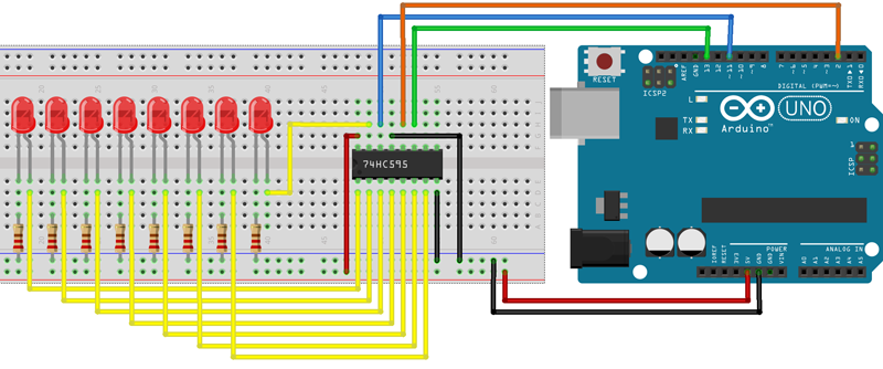
Source Code for 'AND, OR, XOR Calculator'
const int dataPin = 6;
const int clockPin = 7;
const int latchPin = 8;
byte ledMap = 0b11111111;
int delayTime = 3000;
void setup() {
  // put your setup code here, to run once:
  pinMode(dataPin, OUTPUT);
  pinMode(clockPin, OUTPUT);
  pinMode(latchPin, OUTPUT);

  Serial.begin(9600);
  shiftWrite(0x00);
  Serial.println("Enter a number between 0-255");
}
void loop() {
  if(Serial.available())
  {
    int inputVal = Serial.parseInt();

    if(inputVal > 255)
    {
      Serial.println("Uh oh, try again");
      Serial.println("Enter a number between 0-255");
      return;
    }

    Serial.print("DECIMAL: ");
    Serial.println(inputVal);
    Serial.print("BINARY: ");
    Serial.println(inputVal, BIN);
    Serial.println();

    Serial.print("AND result: ");
    Serial.println(ledMap & inputVal, BIN);
    shiftWrite(ledMap & inputVal);
    delay(delayTime);

    Serial.print("OR  result: ");
    Serial.println(ledMap | inputVal, BIN);
    shiftWrite(ledMap | inputVal);
    delay(delayTime);

    Serial.print("XOR result: ");
    Serial.println(ledMap ^ inputVal, BIN);
    shiftWrite(ledMap ^ inputVal);
    delay(delayTime);
    Serial.println();
    Serial.println("Enter a number between 0-255");
  }
}
void shiftWrite(byte value)
{
  digitalWrite(latchPin, LOW);
  shiftOut(dataPin, clockPin, MSBFIRST, value);
  digitalWrite(latchPin, HIGH);
}
Wiring Diagram for 'AND, OR, XOR Calculator'

4.4 EEPROM
In this section, we'll learn about storing data in the non-volatile memory known as EEPROM. This allows data to be retained when power is disconnected and accessed later.
Section Resources:
Source Code for 'EEPROM Counter'
#include <EEPROM.h>

// pin definitions
int ledPin = 13;
int buttonPin = 2;

// global variables
int lastButtonState = 1;
long unsigned int lastPress;
int debounceTime = 20;
int counter;

void setup() {
  // setup pin modes
  pinMode(ledPin, OUTPUT);
  pinMode(buttonPin, INPUT_PULLUP);

  //initialise Serial port
  Serial.begin(9600);

  //assign counter the value of address 0
  counter = EEPROM.read(0);
  //write a 0 to address 0. This allows for consecutive resets to reset the counter
  EEPROM.write(0,0);
}

void loop() {
  int buttonState = digitalRead(buttonPin);   //read the state of buttonPin and store it as buttonState (0 or 1)

  if((millis() - lastPress) > debounceTime)   //if the time between the last buttonChange is greater than the debounceTime
  {
    lastPress = millis();   //update lastPress
    if(buttonState == 0 && lastButtonState == 1)    //if button is pressed and was released last change
    {
      counter++;
      EEPROM.write(0, counter); //write counter to address 0
      digitalWrite(ledPin, HIGH); //momentary LED
      lastButtonState = 0;    //record the lastButtonState

      //print the results
      Serial.print("Counter: ");
      Serial.println(counter);
    }
    if(buttonState == 1 && lastButtonState == 0)    //if button is not pressed, and was pressed last change
    {
      lastButtonState = 1;    //record the lastButtonState
      digitalWrite(ledPin, LOW);  //momentary LED
    }
  }
}
Wiring Diagram for 'EEPROM Counter'
Chapter 5: Libraries, Serial Data, and Hardware
5.0 Chapter Overview
In this chapter you'll learn about:
- Using and including libraries in your projects
- Using the SPI interface to send/receive serial data
- Using the I2C interface to send/receive serial data
- Expanding your project with the Arduino hardware format called 'Shields'
5.1 Using and Including Libraries
In this section, we'll be looking at using code modules called 'libraries' which can be used to simplify complex applications.
Section Resources:
Arduino Library Reference Page
Here, you can find Arduino's information page regarding libraries which cover some of the changes for including and adding libraries with different revisions of the Arduino IDE.
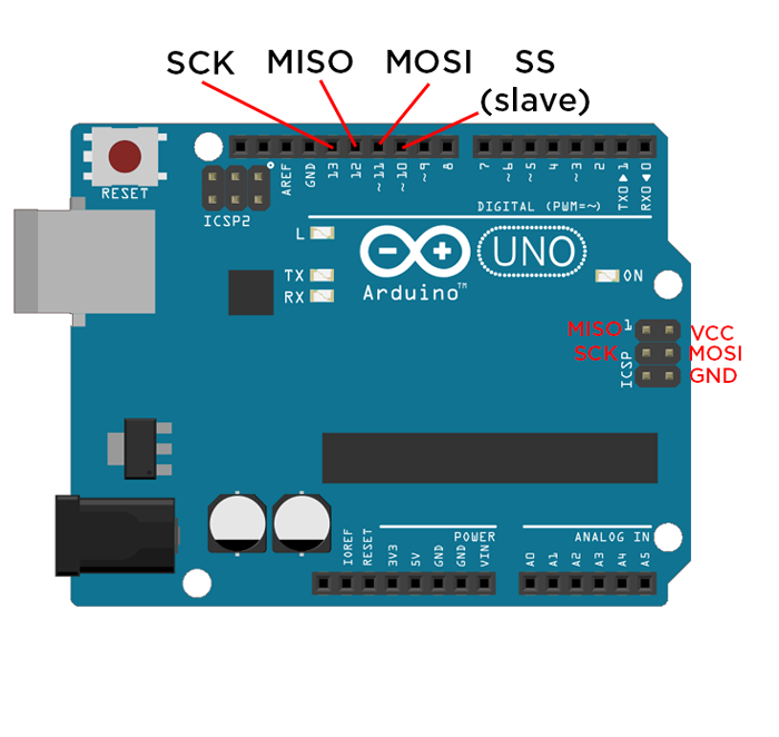
5.2 Using SPI
In this section, you'll learn how to use the SPI interface to send and receive serial data for interfacing with sensors and other devices.
Section Resources:
Arduino SPI Port
Source Code for 'SPI LED Shift Register'
#include <SPI.h>

int slaveSelect = 2;

int delayTime = 50;

void setup() {
  pinMode(slaveSelect, OUTPUT);
  SPI.begin();
  SPI.setBitOrder(LSBFIRST);
}

void loop() {
  for (int i; i < 256; i++)        //For loop to set data = 0 then increase it by one for every iteration of the loop, when the counter reaches the condition (256) it will be reset
  {
    digitalWrite(slaveSelect, LOW);            //Write our Slave select low to enable the SHift register to begin listening for data
    SPI.transfer(i);                     //Transfer the 8-bit value of data to shift register, remembering that the least significant bit goes first
    digitalWrite(slaveSelect, HIGH);           //Once the transfer is complete, set the latch back to high to stop the shift register listening for data
    delay(delayTime);                             //Delay
  }
}
Wiring Diagram for 'SPI LED Shift Register'
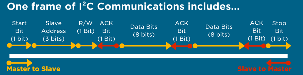
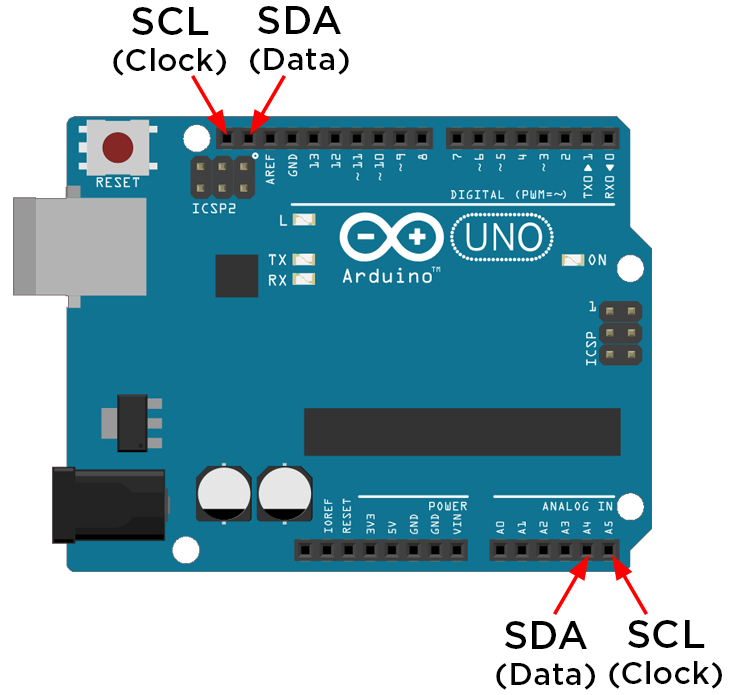
5.3 Using I2C
In this section, you'll look at using the I2C interface to send and receive serial data for interfacing with sensors and other devices.
Section Resources:
I2C Packet Structure
Arduino I2C Port
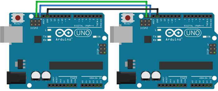
Source Code for 'Master Reader Arduino Demo (from Arduino)'
#include <Wire.h>

void setup() {
  Wire.begin();        // join i2c bus (address optional for master)
  Serial.begin(9600);  // start serial for output
}

void loop() {
  Wire.requestFrom(8, 6);    // request 6 bytes from slave device #8

  while (Wire.available()) { // slave may send less than requested
    char c = Wire.read(); // receive a byte as character
    Serial.println(c);         // print the character
  }

  delay(500);
}
Source Code for 'Slave Sender Arduino Demo (from Arduino)'
#include <Wire.h>

void setup() {
  Wire.begin(8);                // join i2c bus with address #8
  Wire.onRequest(requestEvent); // register event
}

void loop() {
  delay(100);
}

// function that executes whenever data is requested by master
// this function is registered as an event, see setup()
void requestEvent() {

  Wire.write("hello "); // respond with message of 6 bytes
  // as expected by master
}
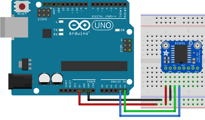
Adafruit RTC Library
You can download Adafruit's RTC library which is specifically designed for the DS3231 chip that we'll be using, here.
Wiring Diagram for 'I2C-I2C Arduino Demo'
Source Code for 'RTC Module (from Adafruit)'
// Date and time functions using a DS3231 RTC connected via I2C and Wire lib
#include <Wire.h>
#include "RTClib.h"

RTC_DS3231 rtc;

char daysOfTheWeek[7][12] = {"Sunday", "Monday", "Tuesday", "Wednesday", "Thursday", "Friday", "Saturday"};

void setup () {

#ifndef ESP8266
  while (!Serial); // for Leonardo/Micro/Zero
#endif

  Serial.begin(9600);

  delay(3000); // wait for console opening

  if (! rtc.begin()) {
    Serial.println("Couldn't find RTC");
    while (1);
  }

  if (rtc.lostPower()) {
    Serial.println("RTC lost power, lets set the time!");
    // following line sets the RTC to the date & time this sketch was compiled
    rtc.adjust(DateTime(F(__DATE__), F(__TIME__)));
    // This line sets the RTC with an explicit date & time, for example to set
    // January 21, 2014 at 3am you would call:
    // rtc.adjust(DateTime(2014, 1, 21, 3, 0, 0));
  }
}

void loop () {
    DateTime now = rtc.now();

    Serial.print(now.year(), DEC);
    Serial.print('/');
    Serial.print(now.month(), DEC);
    Serial.print('/');
    Serial.print(now.day(), DEC);
    Serial.print(" (");
    Serial.print(daysOfTheWeek[now.dayOfTheWeek()]);
    Serial.print(") ");
    Serial.print(now.hour(), DEC);
    Serial.print(':');
    Serial.print(now.minute(), DEC);
    Serial.print(':');
    Serial.print(now.second(), DEC);
    Serial.println();

    Serial.print(" since midnight 1/1/1970 = ");
    Serial.print(now.unixtime());
    Serial.print("s = ");
    Serial.print(now.unixtime() / 86400L);
    Serial.println("d");

    // calculate a date which is 7 days and 30 seconds into the future
    DateTime future (now + TimeSpan(7,12,30,6));

    Serial.print(" now + 7d + 30s: ");
    Serial.print(future.year(), DEC);
    Serial.print('/');
    Serial.print(future.month(), DEC);
    Serial.print('/');
    Serial.print(future.day(), DEC);
    Serial.print(' ');
    Serial.print(future.hour(), DEC);
    Serial.print(':');
    Serial.print(future.minute(), DEC);
    Serial.print(':');
    Serial.print(future.second(), DEC);
    Serial.println();

    Serial.println();
    delay(3000);
}
Wiring Diagram for 'RTC Module'
5.4 Interrupts
In this section, we'll look at how to use interrupts. You may have heard of them before, and they're a great way to increase your program's efficiency when dealing with hardware inputs.
Section Resources:
Source Code for 'Interrupt Debouncing'
// pin definitions
int ledPin = 3;
int buttonPin = 2;

// global variables
int toggleState;
int lastButtonState = 1;
long unsigned int lastPress;
volatile int buttonFlag;
int debounceTime = 20;

void setup() {
  // setup pin modes
  pinMode(ledPin, OUTPUT);
  pinMode(buttonPin, INPUT_PULLUP);
  attachInterrupt(digitalPinToInterrupt(2), ISR_button, CHANGE);
}

void loop() {
  if((millis() - lastPress) > debounceTime && buttonFlag)
  {
    lastPress = millis();   //update lastPress
    if(digitalRead(buttonPin) == 0 && lastButtonState == 1)    //if button is pressed and was released last change
    {
      toggleState =! toggleState;                 //toggle the LED state
      digitalWrite(ledPin, toggleState);
      lastButtonState = 0;    //record the lastButtonState
    }

    else if(digitalRead(buttonPin) == 1 && lastButtonState == 0)    //if button is not pressed, and was pressed last change
    {
      lastButtonState = 1;    //record the lastButtonState
    }
    buttonFlag = 0;
  }
}

void ISR_button()
{
  buttonFlag = 1;
}
Wiring Diagram for 'Interrupt Debouncing'
5.5 Arduino Shields
In this section, we'll be taking a look at using hardware add-on modules known as 'shields'. They're a great way to easily expand your project's capabilities.
Chapter 6: Where to From Here?
6.0 Further Resources
It's time to wrap up the Arduino Workshop, so I'm going to recommend a couple of my favourite resources for projects and questions.

