


Romi Encoder Pair Kit, 12 CPR, 3.5-18V
Available with a lead time
Expect dispatch between Jul 31 and Aug 03
Quantity Discounts:
- 10+ $14.62 (exc GST)
- 25+ $14.16 (exc GST)
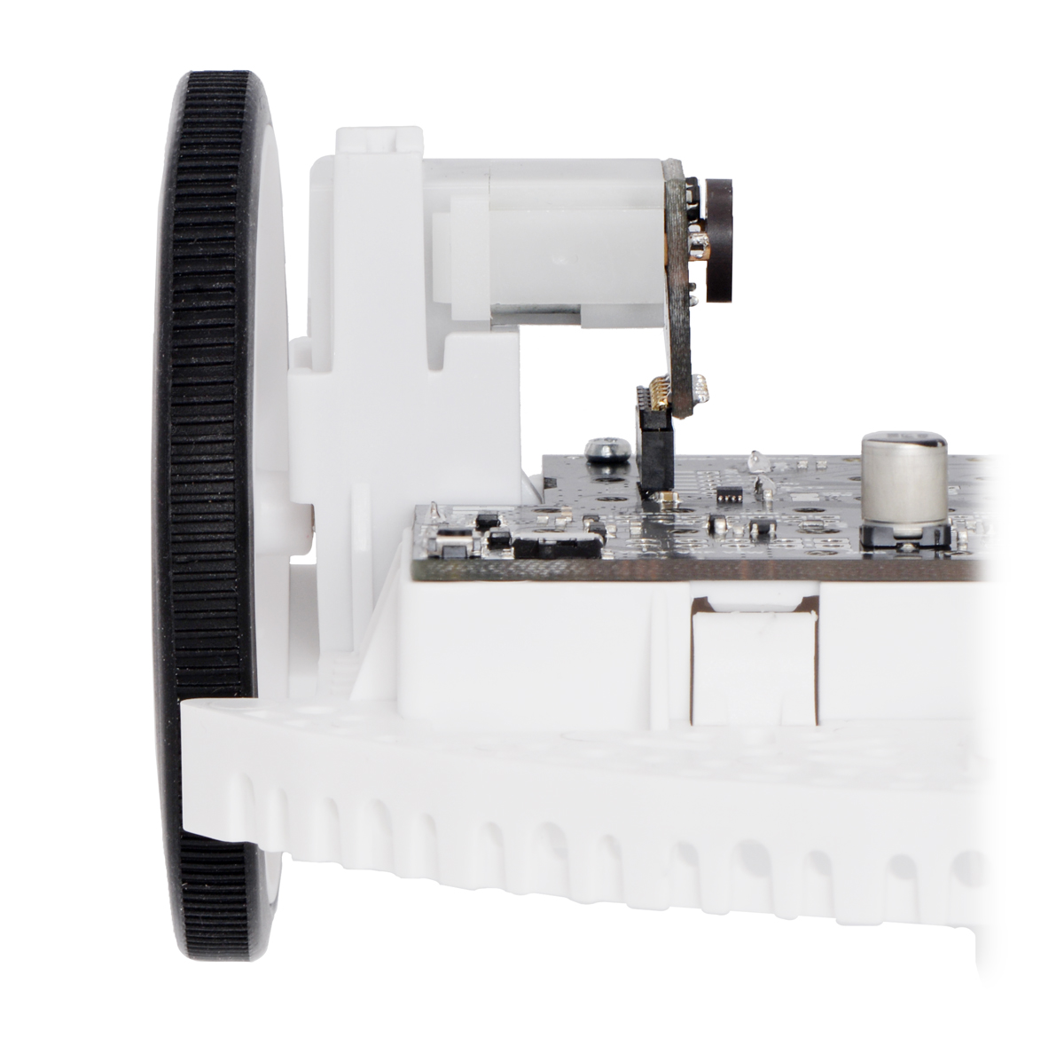
This kit includes two dual-channel Hall effect sensor boards and two 6-pole magnetic discs that can be used to add quadrature encoding to the mini plastic gearmotors on a Romi chassis. The encoder board senses the rotation of the magnetic disc and provides a resolution of 12 counts per revolution of the motor shaft when counting both edges of both channels, which corresponds to approximately 1440 counts per revolution of the Romi’s wheels.
This compact encoder solution fits within the 11.5 mm × 22.5 mm cross section of the rear of the motors on three of the four sides. The fourth side of the encoder has the signal and power connections, and it extends 7 mm past the edge of the motor so that it is at just the right height to be able to plug into a board mounted below on the Romi chassis when the included low-profile male and female header pins are used. The assembly does not extend past the end of the extended motor shaft, which protrudes 5 mm beyond the back of the motor.
Pinout and installation
The encoder board is designed to be soldered directly to the back of the motor, with the back shaft of the motor protruding through the hole in the middle of the circuit board. One way to achieve good alignment between the board and the motor is to tack down the board to one motor pin and to solder the other pin only when the board is flat and well aligned. Be careful to avoid prolonged heating of the motor pins, which could deform the motor case or brushes.
Pololu currently have two boards that the these encoders can directly plug into: the Romi 32U4 Control Board and the Motor Driver and Power Distribution Board for Romi Chassis. The encoder pins need to be installed pointing down toward the chassis in order to be able to plug into this board.
|
|

For robots not using these boards, it might be more convenient to install the board and pins facing up and connect to them with a cable made from Pololu's wires with pre-crimped terminals.
 |
The included low-profile headers are still long enough to work with Pololu's pre-crimped jumper wires. |
|---|
To later use the same encoders with a board that they can plug into, just pull the motor portion off of the gearbox, rotate it 180°, and push it back in to make the encoder and pins point down.
|
|


If you do not care about compatibility with existing or potential future boards, Pololu recommend soldering wires directly to the encoder or installing a standard-length male header that works better with cables made from Pololu's wires with pre-crimped terminals.
 |
A standard-length straight 0.1" male header allows for compact cable connection. |
|---|
Once the board is soldered down to the two terminals, the motor leads are connected to the M1 and M2 pads along the edge of the board; the remaining four pads are used to power the sensors and access the two quadrature outputs:
|
|


The sensors are powered through the VCC and GND pins. VCC can be 3.5 V to 18 V, and the quadrature outputs A and B are open-drain digital signals that need to be pulled up to the appropriate logic voltage of your system. The encoder boards have pads for optional 0603 size surface-mount resistors to pull the outputs up to VCC, but in typical applications, the pull-up resistors will be on the main electronics board.
 |
Encoder A and B outputs of a magnetic encoder on a high-power (HP) mini plastic gearmotor running at 4.5 V. |
|---|
The board’s six through-holes have a 0.1" (2.54 mm) pitch, so Pololu are compatible with common 0.1" connectors, or you can just solder individual wires directly to the board.
Once the board is soldered to the motor, the magnetic encoder disc can be pushed onto the motor shaft. One easy way to accomplish this is to press the motor onto the disc while it is sitting on a flat surface, pushing until the shaft makes contact with that surface. The size of the gap between the encoder disc and the sensor board does not have a big impact on performance as long as the motor shaft is at least all the way through the disc.
Schematic diagram
 |
This schematic is also available as a downloadable pdf (88k pdf).
People often buy this product together with:
 | 8×2 Character LCD - Black Bezel (Parallel Interface) |
 | Romi Chassis Ball Caster Kit - Black |
 | Romi Chassis Kit - Black |
Dimensions
| Size: | 20 mm × 18.7 mm1 |
|---|---|
| Weight: | 3.0 g2 |
General specifications
| Minimum operating voltage: | 3.5 V |
|---|---|
| Maximum operating voltage: | 18 V |
Identifying markings
| PCB dev codes: | rom03a |
|---|---|
| Other PCB markings: | 0J10033 |
Notes:
- 1
- The assembled encoder will extend 5 mm beyond the back of the motor (it fits entirely within the length of the extended motor shaft).
- 2
- Combined weight of two encoder PCBs and two magnetic discs. Each encoder board weighs ~0.9 g and each magnet disc weighs ~0.6 g.
File downloads
-
Dimension diagram of the Romi Encoder Pair Kit, 12 CPR, 3.5-18V (249k pdf)
-
Drill guide for the Romi Encoder Pair Kit, 12 CPR, 3.5-18V (37k dxf)
This DXF drawing shows the locations of all of the board’s holes.
-
3D models of Romi Encoder Pair Kit, 12 CPR, 3.5-18V (1MB zip)
This file contains 3D models (in the step file format) of the components for the Romi Encoder Pair Kit, 12 CPR, 3.5-18V.
Exact shipping can be calculated on the view cart page (no login required).
Products that weigh more than 0.5 KG may cost more than what's shown (for example, test equipment, machines, >500mL liquids, etc).
We deliver Australia-wide with these options (depends on the final destination - you can get a quote on the view cart page):
- $3+ for Stamped Mail (typically 10+ business days, not tracked, only available on selected small items)
- $7+ for Standard Post (typically 6+ business days, tracked)
- $11+ for Express Post (typically 2+ business days, tracked)
- Pickup - Free! Only available to customers who live in the Newcastle region (must order online and only pickup after we email to notify you the order is ready). Orders placed after 2PM may not be ready until the following business day.
Non-metro addresses in WA, NT, SA & TAS can take 2+ days in addition to the above information.
Some batteries (such as LiPo) can't be shipped by Air. During checkout, Express Post and International Methods will not be an option if you have that type of battery in your shopping cart.
International Orders - the following rates are for New Zealand and will vary for other countries:
- $12+ for Pack and Track (3+ days, tracked)
- $16+ for Express International (2-5 days, tracked)
If you order lots of gear, the postage amount will increase based on the weight of your order.
Our physical address (here's a PDF which includes other key business details):
40 Aruma Place
Cardiff
NSW, 2285
Australia
Take a look at our customer service page if you have other questions such as "do we do purchase orders" (yes!) or "are prices GST inclusive" (yes they are!). We're here to help - get in touch with us to talk shop.
Have a product question? We're here to help!
 Magnetic Encoder Disc for Micro Metal Gearmotors, 12 CPRSKU: POLOLU-2599 Brand: PololuThese magnetic discs can be used with Pololu's micro metal gearmotors with exten ...
- Hobby Gearmotor - 140 RPM (Pair)SKU: ROB-13302 Brand: SparkfunThese are a pair of hobby gearmotors from DAGU. These gearmotors are the same on ...
- Brushless DC Motor with Encoder 12V 159RPMSKU: FIT0441 Brand: DFRobotThis is a motor revolution: a new DC brushless motor with built-in motor driver. ...
- T-Slot Photo Interrupter with 1 Meter CableSKU: ADA3985 Brand: AdafruitThis T-Slot Photo Interrupter with Cable is a simple plastic sensor with two ele ...


- MicroSD Memory Card - 16GB Class 10SKU: CE04628 Brand: Core ElectronicsAdd speedy mega-storage in a jiffy using this 16 GB Class 10 micro-SD card
- Raspberry Pi 3 Model B+SKU: CE05436 Brand: Raspberry PiThe Raspberry Pi 3 Model B+ (note the plus on the end) was released by the Raspb ...
- Romi 32U4 Control BoardSKU: POLOLU-3544 Brand: PololuThe Romi 32U4 Control Board turns the Romi chassis into a programmable robot bas ...
- Romi Chassis Kit - PinkSKU: POLOLU-3501 Brand: PololuThe versatile Romi chassis is a great starting point for your next mobile robot. ...


Guides

The Maker Revolution
Projects

The Rats Nest VCC Desktop Power Supply

Remote-Controlled Mars Rover

FlipperMate: Hands-Free Pinball

Makers love reviews as much as you do, please follow this link to review the products you have purchased.
Product Comments