
Pololu Adjustable 4-12V Step-Up/Step-Down Voltage Regulator S18V20ALV
Available with a lead time
Expect dispatch between Aug 07 and Aug 10
Quantity Discounts:
- 6+ $48.05 (exc GST)
- 12+ $46.55 (exc GST)
 |
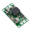
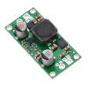
These step-up/step-down regulators take an input voltage from 3 V to 30 V and increase or decrease it as necessary to produce an adjustable 4 V to 12 V or 9 V to 30 V output, depending on the version. They are switching regulators (also called switched-mode power supplies (SMPS) or DC-to-DC converters) with a single-ended primary-inductor converter (SEPIC) topology, and they have a typical efficiency between 80% and 90%. The available output current is a function of the input voltage, output voltage, and efficiency (see the Typical Efficiency and Output Current section below), but it will be around 2 A when the input voltage is close to the output voltage.
The S18V20x regulator family consists of the two adjustable-output versions mentioned above along with five versions that output a fixed 5 V, 6 V, 9 V, 12 V, or 24 V. The different versions of the board all look very similar, so the bottom silkscreen includes a blank space where you can add your own distinguishing marks or labels. This product page applies to both adjustable-output versions of the S18V20x family.
The flexibility in input voltage offered by these regulators is especially well-suited for battery-powered applications in which the battery voltage begins above the desired output voltage and drops below the target as the battery discharges. Without the typical restriction on the battery voltage staying above the required voltage throughout its life, new battery packs and form factors can be considered. For example:
- A 4-cell battery holder, which might have a 6 V output with fresh alkalines or a 4.0 V output with partially discharged NiMH cells, can be used with the 5V version of this regulator to power a 5 V circuit.
- A disposable 9 V battery powering a 5V circuit can be discharged to under 3 V instead of cutting out at 6 V, as with typical linear or step-down regulators.
- The 6V version of this regulator can be used to enable a wide range of power supply options for a hobby servo project.
The no-load quiescent will typically be between 1 mA and 5 mA for most combinations of input and output voltages, though the combination of a very high output voltage and a very low input voltage (e.g. when boosting from 3 V in to 24 V out) can result in quiescent currents on the order of a few dozen milliamps.
The ENABLE pin can be used to put the board in a low-power state that reduces the quiescent current to between 10 and 20 µA per volt on VIN (e.g. approximately 30 µA with 3 V in and 500 µA with 30 V in).
This regulator has built-in reverse-voltage protection, over-current protection, thermal shutdown (which typically activates at 165°C), and an under-voltage lockout that causes the regulator to turn off when the input voltage is below 2.5 V (typical).
For similarly powerful boost-only regulators, consider Pololu's U3V50x regulator family, which are typically more appropriate if you know that your input voltage will always be lower than your output voltage.
Features
- Input voltage: 2.9 V to 32 V1
- Output adjustable from 4 V to 12 V or 9 V to 30 V
- Typical maximum output current: 2 A (when input voltage is close to the output voltage; the Typical Efficiency and Output Current section below shows how the achievable output current depends on input and output voltages)
- Integrated reverse-voltage protection (up to 30 V), over-current protection, over-temperature shutoff, and under-voltage lockout
- Typical efficiency of 80% to 90%, depending on input voltage, output voltage, and load
- Four mounting holes for #2 or M2 screws
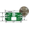
- Compact size: 1.7" × 0.825" × 0.38" (43 × 21 × 10 mm)
- Smaller holes for 0.1" header pins and larger holes for terminal blocks offer several options for connecting to the board
1 32 V is the absolute maximum operating voltage; the recommended maximum operating voltage is 30 V, which is the limit of the reverse voltage protection.
Using the regulator
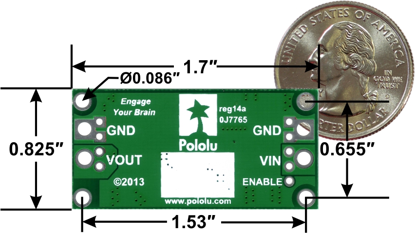
Connections
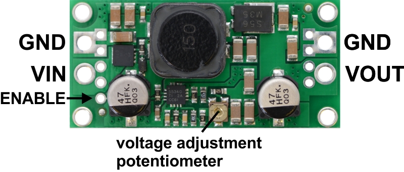
This step-up/step-down regulator has four connections: input voltage (VIN), ground (GND), and output voltage (VOUT), and ENABLE.
 |
The input voltage, VIN, should be between 2.9 V and 32 V. Lower input voltages can cause the regulator to shut down or behave erratically; higher input voltages can destroy the regulator, so you should ensure that noise on the input is not excessive. 32 V should be treated as the absolute maximum input voltage. Pololu's recommended maximum operating voltage is 30 V, which is the limit of the reverse voltage protection. Additionally, Pololu recommend keeping the sum of the input and output voltages below 55 V; see the Setting the Output Voltage section below for more information.
The regulator is enabled by default: a 100 kO pull-up resistor on the board connects the ENABLE pin to reverse-protected VIN. The ENABLE pin can be driven low (under 0.7 V) to put the board into a low-power state. The quiescent current draw in this sleep mode is dominated by the current in the pull-up resistor from ENABLE to VIN and by the reverse-voltage protection circuit, which will draw between 10 µA and 20 µA per volt on VIN when ENABLE is held low (e.g. approximately 30 µA with 3 V in and 500 µA with 30 V in). If you do not need this feature, you should leave the ENABLE pin disconnected. Note that the SEPIC topology has an inherent capacitor from input to output; therefore, the output is not completely disconnected from the input even when the regulator is shut down.
|
|
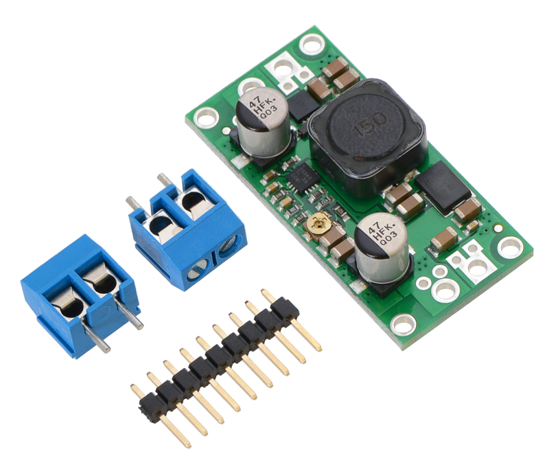
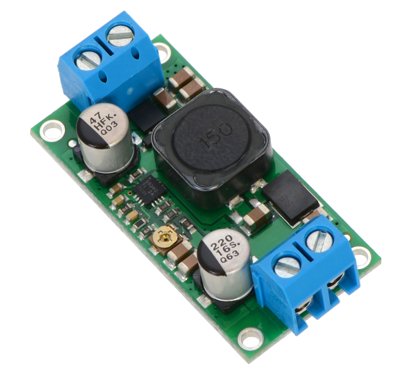
The connections are labeled on the back side of the PCB, and the board offers several options for making electrical connections. You can solder the included 2-pin 5mm-pitch terminal blocks to the two pairs of larger holes on the ends of the board. Alternatively, if you want to use this regulator with a solderless breadboard, 0.1"-pitch connectors, or other prototyping arrangements that use a 0.1"grid, you can solder pieces of the included 9×1 straight male header strip to the 0.1"-spaced smaller holes (each large through-hole has a corresponding pair of these smaller holes). For the most compact installation, you can solder wires directly to the board.
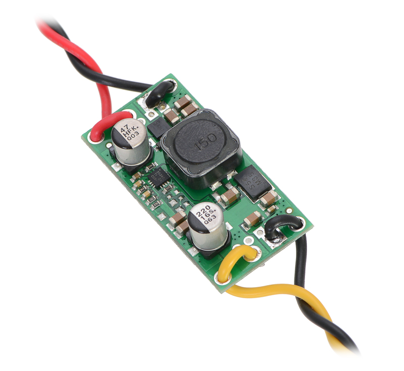 |
The board has four mounting holes intended for #2 or M2 screws. In applications where mounting screws are not used and wires are soldered directly to the board, the insulated part of the wires can be passed through the mounting holes for strain relief. The picture above shows an example of this with 20 AWG wire, which was close to the limit of what would fit through the mounting holes.
Setting the output voltage
The output voltage can be adjusted using a multimeter and a light load (e.g. a 10 kO to 100 kO resistor). Turning the potentiometer clockwise increases the output voltage. The output voltage can be affected by a screwdriver touching the potentiometer, so the output measurement should be done with nothing touching the potentiometer (also, note that touching parts of the board with your finger can affect the output voltage). The following graph shows the approximate output voltage as a function of the potentiometer position:
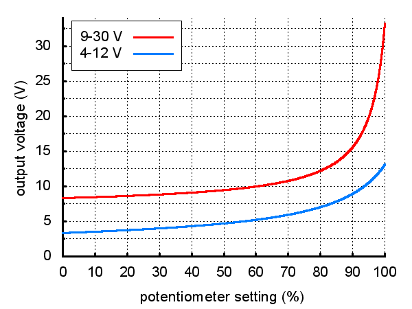 |
Output voltage settings for Pololu adjustable step-up/step-down voltage regulators S18V20ALV (blue line) and S18V20AHV (red line). |
|---|
Note: Pololu recommend against using this regulator in situations where the sum of the input and output voltages exceeds 55 V. For example, if your input voltage could reach 30 V, you should keep the output voltage setting under 25 V. It is typically not very practical to use the AHV version of this regulator beyond about 24 V out; Pololu's U3V50AHV step-up voltage regulator will usually be a more appropriate option for higher-output-voltage applications.
The trimmer potentiometer is not rated for continual adjustment back and forth; the intended application is to set the output voltage a few times in its life.
Typical efficiency and output current
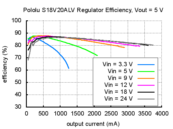
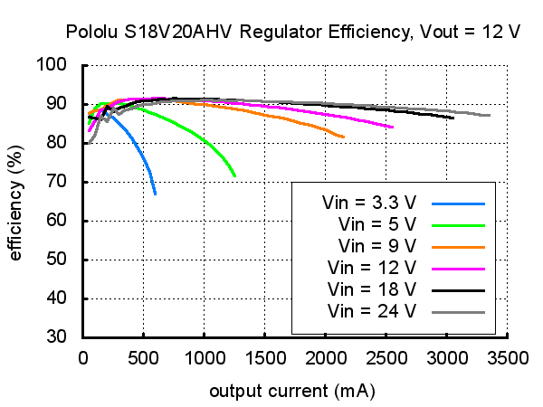
The efficiency of a voltage regulator, defined as (Power out)/(Power in), is an important measure of its performance, especially when battery life or heat are concerns. As shown in the graphs below, these switching regulators have an efficiency of 80% to 90% for most combinations of input voltage, output voltage, and load.
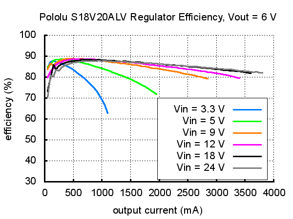
S18V20ALV (4-12 V) efficiencies for various combinations of VIN and VOUT:
 |
 |
 |
 |
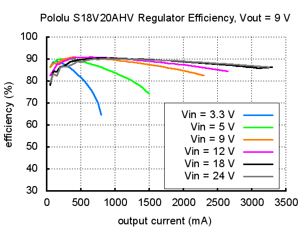
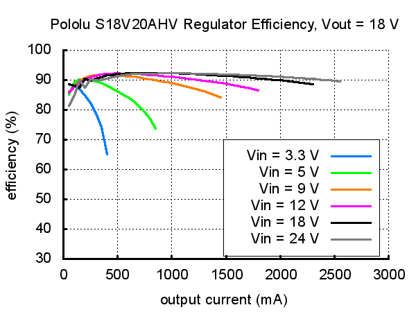
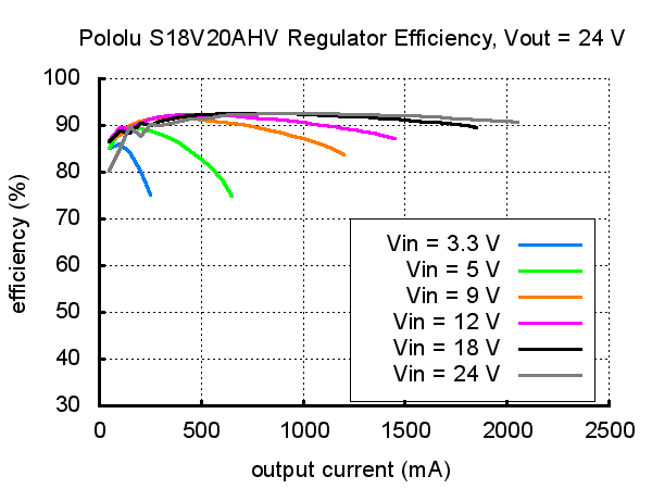
S18V20AHV (9-30 V) efficiencies for various combinations of VIN and VOUT:
 |
 |
 |
 |
Pololu manufacture these boards in-house at Pololu's Las Vegas facility, which gives Pololu the flexibility to make batches of regulators with customized components to better meet the needs of your project. For example, if you have an application where the input voltage will always be below 20 V and efficiency is very important, Pololu can make these regulators a bit more efficient at high loads by replacing the 30V reverse voltage protection MOSFET with a 20V one. Pololu can also customize the set output voltage. If you are interested in customization and want at least a few dozen units, please contact us.
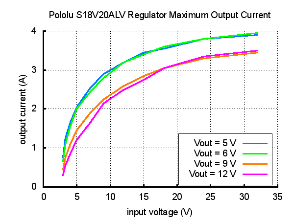
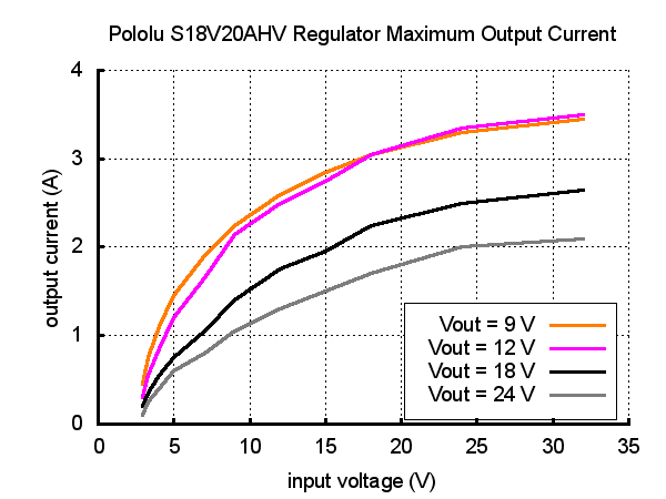
The maximum achievable output current of the board varies with the input voltage but also depends on other factors, including the ambient temperature, air flow, and heat sinking. The graphs below show output currents at which this voltage regulator’s over-temperature protection typically kicks in after a few seconds. These currents represent the limit of the regulator’s capability and cannot be sustained for long periods, so the continuous currents that the regulator can provide are typically several hundred milliamps lower.
 |
 |
During normal operation, this product can get hot enough to burn you. Take care when handling this product or other components connected to it.
People often buy this product together with:
 | Pololu Adjustable Step-Up/Step-Down Voltage Regulator S7V8A |
 | Pololu Adjustable 9-30V Step-Up/Step-Down Voltage Regulator S18V20AHV |
 | Pololu 5V Step-Up/Step-Down Voltage Regulator S18V20F5 |
Dimensions
| Size: | 0.825" × 1.7" × 0.38"1 |
|---|---|
| Weight: | 7.5 g2 |
General specifications
| Minimum operating voltage: | 2.9 V |
|---|---|
| Maximum operating voltage: | 32 V3 |
| Maximum output current: | 2 A4 |
| Minimum output voltage: | 4 V |
| Maximum output voltage: | 12 V |
| Reverse voltage protection?: | Y5 |
| Maximum quiescent current: | 5 mA6 |
Identifying markings
| PCB dev codes: | reg14a |
|---|---|
| Other PCB markings: | 0J7765, blank white box |
Notes:
- 1
- Without included optional headers or terminal blocks. Height with terminal blocks installed is approximately 0.5".
- 2
- Without included optional headers or terminal blocks. Terminal blocks add 3.4 g.
- 3
- Absolute maximum. Recommended maximum operating voltage is 30 V, and reverse voltage protection only works up to 30 V.
- 4
- Under typical conditions, where the input voltage is close to the output voltage. Maximum output current can be higher when stepping down and lower when stepping up.
- 5
- For input voltages up to 30 V.
- 6
- Typical worst case (i.e. with VIN at 3 V and VOUT at 12 V). Quiescent current depends on the input and output voltages and is much lower for most of the input voltage range. The ENABLE pin can be used to reduce this to well under 1 mA.
File downloads
-
Dimension diagram of the S18V20x Step-Up/Step-Down Voltage Regulator (309k pdf)
-
3D model of the S18V20x Step-Up/Step-Down Voltage Regulator (4MB step)
-
Step-Up/Step-Down Voltage Regulator S18V20x drill guide (44k dxf)
This DXF drawing shows the locations of all of the board’s holes.
Exact shipping can be calculated on the view cart page (no login required).
Products that weigh more than 0.5 KG may cost more than what's shown (for example, test equipment, machines, >500mL liquids, etc).
We deliver Australia-wide with these options (depends on the final destination - you can get a quote on the view cart page):
- $3+ for Stamped Mail (typically 10+ business days, not tracked, only available on selected small items)
- $7+ for Standard Post (typically 6+ business days, tracked)
- $11+ for Express Post (typically 2+ business days, tracked)
- Pickup - Free! Only available to customers who live in the Newcastle region (must order online and only pickup after we email to notify you the order is ready). Orders placed after 2PM may not be ready until the following business day.
Non-metro addresses in WA, NT, SA & TAS can take 2+ days in addition to the above information.
Some batteries (such as LiPo) can't be shipped by Air. During checkout, Express Post and International Methods will not be an option if you have that type of battery in your shopping cart.
International Orders - the following rates are for New Zealand and will vary for other countries:
- $12+ for Pack and Track (3+ days, tracked)
- $16+ for Express International (2-5 days, tracked)
If you order lots of gear, the postage amount will increase based on the weight of your order.
Our physical address (here's a PDF which includes other key business details):
40 Aruma Place
Cardiff
NSW, 2285
Australia
Take a look at our customer service page if you have other questions such as "do we do purchase orders" (yes!) or "are prices GST inclusive" (yes they are!). We're here to help - get in touch with us to talk shop.
Have a product question? We're here to help!
 JST-PH 2-Pin SMT Right Angle Breakout BoardSKU: ADA1862 Brand: AdafruitA simple 2-pin connector soldered onto a breadboard-friendly breakout. This is c ...
- Polymer Lithium Ion Battery (LiPo) 3.7V 2400mAhSKU: CE04379 Brand: Core Electronics
Welcome to the awesomeness that is LiPo batteries. Polymer Lithium Ion batter ...
- Polymer Lithium Ion Battery (LiPo) 3.7V 4400mAhSKU: CE04380 Brand: Core ElectronicsThis Lithium Polymer Ion based battery is a slim, lightweight battery that is pe ...
- Micro B USB In-line Power Switch Cable (Female to Male)SKU: CE04814 Brand: Core ElectronicsUnplugging USB devices just to remove power is a thing of the past with this han ...


Videos
View AllGuides

PiicoDev Magnetometer- Getting Started Guide

The Maker Revolution

How to Use DC Regulators/Converters

Powering Portable Projects: Batteries
Projects

Wireless QI Phone Charger Powered by Raspberry Pi

mmPi-Pico HAT

Solar Charging Station

Makers love reviews as much as you do, please follow this link to review the products you have purchased.
Product Comments