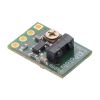
Pololu 38 kHz IR Proximity Sensor, Fixed Gain, High Brightness
In stock, ships same business day if ordered before 2PM
Fastest delivery: Tomorrow*
Disclaimer:
For next-day delivery, the shipping address must
be in the AusPost next-day network, eParcel Express must be selected, and the order must be placed
before 2PM AEST Mon-Thurs excluding NSW Public Holidays. Orders may be delayed due to AusPost
pickup timings and order verifications. eParcel Express is typically a 1-day service within the
AusPost next-day network, though it is sometimes 2+ days.
Quantity Discounts:
- 10+ $14.62 (exc GST)
- 25+ $14.16 (exc GST)
 |
These sensor modules are based on Vishay’s TSSP77038 modulated infrared receivers. Unlike most IR receiver modules designed for remote control of appliances like televisions, the TSSP77038 has a fixed gain (sensitivity) that makes the sensor more predictable when used in proximity or reflectance sensors. The Pololu carrier module combines the TSSP77038 with an IR LED driven by a 555 timer-based circuit to make a complete sensor module that requires only a 3.3 V to 5 V power connection. An enable input allows control of whether or not the IR LED is on, and a digital output indicates whether or not an object is detected. The module is available in low-brightness and high-brightness versions, which provide detection ranges of up to approximately 12 inches (30 cm) and 24 inches (60 cm), respectively. The actual performance depends on many factors, including object size, reflectivity, and ambient lighting conditions.
Pololu carry several through-hole IR receivers that work nicely with the high-brightness LED and 38 kHz modulation circuit of these proximity sensors: the TSSP58038 is a through-hole version of the surface-mount TSSP77038 detector on these proximity sensors, and the TSSP58P38 is a unique modulated IR receiver with an output that can be used to measure distance. You can use several of the proximity sensors with these discrete IR receivers to make sophisticated sensing solutions in which you enable one emitter at a time and monitor the reflections with the other sensors.
Using the sensor
 |
Connections
The proximity sensor has four connections: ground (GND), logic power (VDD), digital detection indicator (OUT), and IR emitter enable (ENABLE).
The logic power, VDD, should be between 3.3 V and 5 V. Supplying less than 5 V will decrease the IR LED brightness and decrease the sensing range. To run the sensor at full brightness while powered at 3.3 V, bridge the surface mount jumper located on the emitter side of the board.
The OUT pin, which is high by default, remains low as long as the TSSP77038 receiver is detecting a sufficient signal. When at the edge of the detection range, this output will alternate between high and low. A red LED on the emitter side of the board is tied to this output and turns on when the pin goes low, providing a visual indication of when the sensor is detecting something.
The ENABLE pin turns off the IR emitter LED when it is set low. This pin is high by default and can be left disconnected if dynamic control of the IR emitter is not needed. A green LED on the emitter side of the board is connected in parallel with the IR LED, making it easy to tell when the IR LED is on.
The four connections are arranged with a 0.1" spacing along the edge of the board for compatibility with solderless breadboards, connectors, and other prototyping arrangements that use a 0.1" grid. You can solder wires directly to the board or solder in either the 4×1 straight male header strip or the 4×1 right-angle male header strip that is included.
 |
Tuning the emitter frequency
The trimmer potentiometer on the receiver side of the sensor can be used to adjust frequency of the IR emitter LED. The sensing distance can be maximized by tuning for 38 kHz, or it can be intentionally detuned to shorten the sensing range. If you have the appropriate equipment, you can tune it by setting the actual frequency, but a simpler approach is to just observe the performance as you turn the pot. The sensor should work to at least some degree over the entire range of the pot.
Limitations
- This sensor will only tell you if an object is within its sensing range, not how far away it is. At the edge of its detection range, the output will alternate between high and low as it sporadically detects (see the left oscilloscope capture below).
- The sensor is merely looking at whether or not it is getting any signal back, so object size and reflectivity (to IR) will affect sensing range.
- The sensing angle is relatively wide in both directions. The high-brightness version in particular might require extra consideration when mounting to prevent seeing surfaces parallel to the sensor’s line of sight. For many applications, additional shielding can be used to block undesirable sensing paths, such as reflections off of the ground, or to reduce interference from ambient lighting. When applying shielding, keep in mind that reflection off the shielding itself can cause undesired activation of the sensor.
- This sensor can be triggered by ambient IR (e.g. from fluorescent lights; see the right oscilloscope capture below). Some optical shielding, such as by having the sensor mounted receiver-side-down when fluorescent lights are above, might mitigate this. Some advanced analysis of the correlation between the output and toggling of the enable input might also be used to mitigate ambient interference.
- Multiple sensors can interfere with each other. Multi-module applications might require use of the enable inputs to limit interference.
Schematic diagram
 |
This schematic is also available as a downloadable pdf (96k pdf).
Differentiating the two versions
The low-brightness and high-brightness versions of this sensor look almost identical, but there are several ways to tell them apart. One is to look at resistors R3 and R4 on the emitter side of the sensor:
 |
Another approach is to use a multimeter to measure the current draw of the sensor; the low-brightness version draws approximately 8 mA at 5 V while the high-brightness version draws approximately 16 mA at 5 V.
Note: This product replaces Pololu's original irs05a 38 kHz IR proximity sensor, which was also available in high-brightness and low-brightness versions. The main changes are the locations of the emitter LED and IR detector, which have been moved away from the edge of the board. This results in better shielding from the PCB itself, which improves performance. These new irs05b versions have the same dimensions and pinout as the originals and are intended as drop-in replacements for any applications that can tolerate the change in component locations.
People often buy this product together with:
 | Mini Slide Switch: 3-Pin, SPDT, 0.3A (3-Pack) |
 | Shaftless Vibration Motor 10x3.4mm |
 | Shaftless Vibration Motor 10x2.0mm |
Dimensions
| Size: | 0.4" × 0.6" × 0.2"1 |
|---|---|
| Weight: | 0.6 g1 |
General specifications
| Maximum range: | 24 in2 |
|---|---|
| Sampling rate: | 1 kHz |
| Average input current: | 16 mA |
Identifying markings
| PCB dev codes: | irs05b |
|---|
Notes:
- 1
- Without included optional headers.
- 2
- The actual range depends on many factors, including object size, reflectivity, and ambient lighting conditions.
File downloads
-
Schematic diagram of the Pololu 38 kHz IR proximity sensor (96k pdf)
-
Dimension diagram of the Pololu 38 kHz IR Proximity Sensor (300k pdf)
-
3D model of the Pololu 38 kHz IR Proximity Sensor (4MB step)
-
Drill guide for the Pololu 38 kHz IR Proximity Sensor (16k dxf)
This DXF drawing shows the locations of all of the board’s holes.
Exact shipping can be calculated on the view cart page (no login required).
Products that weigh more than 0.5 KG may cost more than what's shown (for example, test equipment, machines, >500mL liquids, etc).
We deliver Australia-wide with these options (depends on the final destination - you can get a quote on the view cart page):
- $3+ for Stamped Mail (typically 10+ business days, not tracked, only available on selected small items)
- $7+ for Standard Post (typically 6+ business days, tracked)
- $11+ for Express Post (typically 2+ business days, tracked)
- Pickup - Free! Only available to customers who live in the Newcastle region (must order online and only pickup after we email to notify you the order is ready). Orders placed after 2PM may not be ready until the following business day.
Non-metro addresses in WA, NT, SA & TAS can take 2+ days in addition to the above information.
Some batteries (such as LiPo) can't be shipped by Air. During checkout, Express Post and International Methods will not be an option if you have that type of battery in your shopping cart.
International Orders - the following rates are for New Zealand and will vary for other countries:
- $12+ for Pack and Track (3+ days, tracked)
- $16+ for Express International (2-5 days, tracked)
If you order lots of gear, the postage amount will increase based on the weight of your order.
Our physical address (here's a PDF which includes other key business details):
40 Aruma Place
Cardiff
NSW, 2285
Australia
Take a look at our customer service page if you have other questions such as "do we do purchase orders" (yes!) or "are prices GST inclusive" (yes they are!). We're here to help - get in touch with us to talk shop.
Have a product question? We're here to help!
Videos
View AllGuides
The Maker Revolution
Getting Hands-on with Sensors
Projects
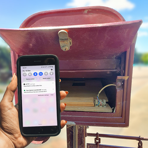
Mailbox Delivery Notification System
WhyzaGC - Feather ESP32 addon to the MightyOhm Gieger Counter
ESP32 IR-Triggered Camera with Home Assistant Integration
Makers love reviews as much as you do, please follow this link to review the products you have purchased.







Product Comments