


MP6550 Single Brushed DC Motor Driver Carrier
In stock, ships same business day if ordered before 2PM
Fastest delivery: Tomorrow*
Disclaimer:
For next-day delivery, the shipping address must
be in the AusPost next-day network, eParcel Express must be selected, and the order must be placed
before 2PM AEST Mon-Thurs excluding NSW Public Holidays. Orders may be delayed due to AusPost
pickup timings and order verifications. eParcel Express is typically a 1-day service within the
AusPost next-day network, though it is sometimes 2+ days.
Quantity Discounts:
- 10+ $8.60 (exc GST)
- 25+ $8.33 (exc GST)
 |
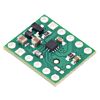
MP6550 Single Brushed DC Motor Driver Carrier, bottom view with dimensions. |
|---|
The MP6550 from Monolithic Power Systems (MPS) is an H-bridge motor driver IC that can be used for bidirectional control of one brushed DC motor at 1.8 V to 22 V. It can supply up to about 1.7 A continuously and features configurable current sensing and current limiting. Since this board is a carrier for the MP6550, Pololu recommend careful reading of the MP6550 datasheet (714k pdf). The board ships populated with all of its SMD components, including the MP6550.
Features
- H-bridge motor driver: can drive one DC motor
- Motor supply voltage: 1.8 V to 22 V
- Logic supply voltage: 1.8 V to 5 V
- Output current: up to 1.7 A continuous; operation at low motor and logic supply voltages reduces the maximum continuous output current
- Current control limits peak current to 2.5 A by default (this limit can be adjusted)
- Under-voltage lockout and protection against over-current and over-temperature
- Carrier board adds reverse-voltage protection up to 20 V
- Compact size (0.5"×0.6")
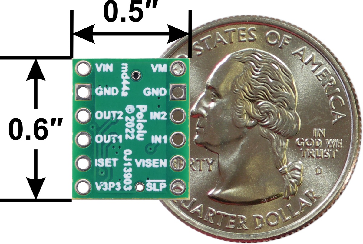
Included hardware
|
|
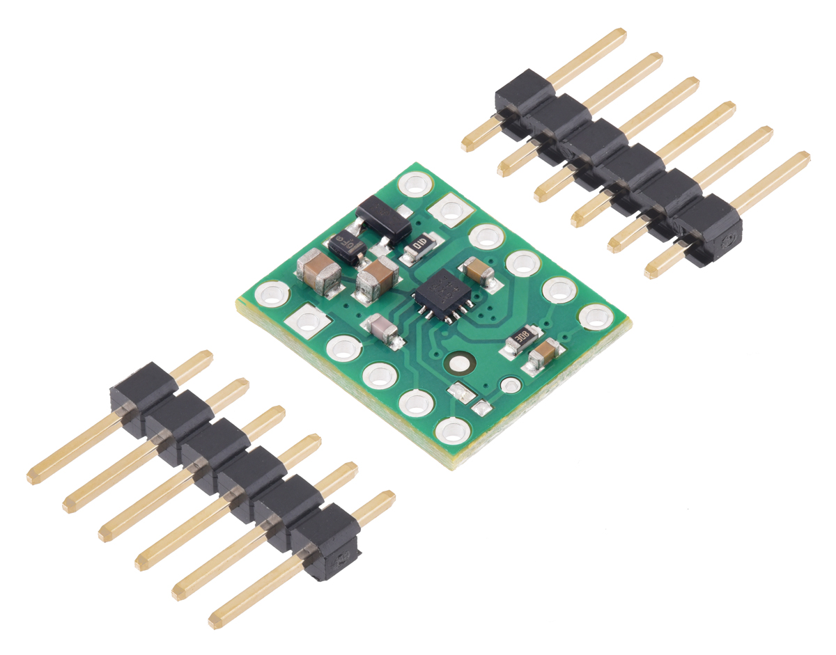
Two 1×6-pin breakaway 0.1" male headers are included with the MP6550 motor driver carrier, which can be soldered in to use the driver with breadboards, perfboards, or 0.1" female connectors. (The headers might ship as a single 1×12 piece that can be broken in half.) The right picture above shows the two possible board orientations when used with these header pins (parts visible or silkscreen visible). You can also solder your motor leads and other connections directly to the board.
Using the motor driver
 |
Minimal wiring diagram for connecting a microcontroller to a MP6550 Single Brushed DC Motor Driver Carrier. |
|---|
In a typical application, power connections are made on one side of the board and control connections are made on the other. Aside from motor and power connections (including a logic voltage connection to SLEEP), the only required control pins are IN1 and IN2.
The following simplified truth table shows how the driver operates:
| IN1 | IN2 | OUT1 | OUT2 | operating mode |
|---|---|---|---|---|
| 0 | 0 | Z | Z | coast (outputs off) |
| PWM | 0 | PWM (H/Z) | PWM (L/Z) | forward/coast at speed PWM % |
| 0 | PWM | PWM (L/Z) | PWM (H/Z) | reverse/coast at speed PWM % |
| PWM | 1 | L | PWM (L/H) | reverse/brake at speed 100% - PWM % |
| 1 | PWM | PWM (L/H) | L | forward/brake at speed 100% - PWM % |
| 1 | 1 | L | L | brake low (outputs shorted to ground) |
Pinout
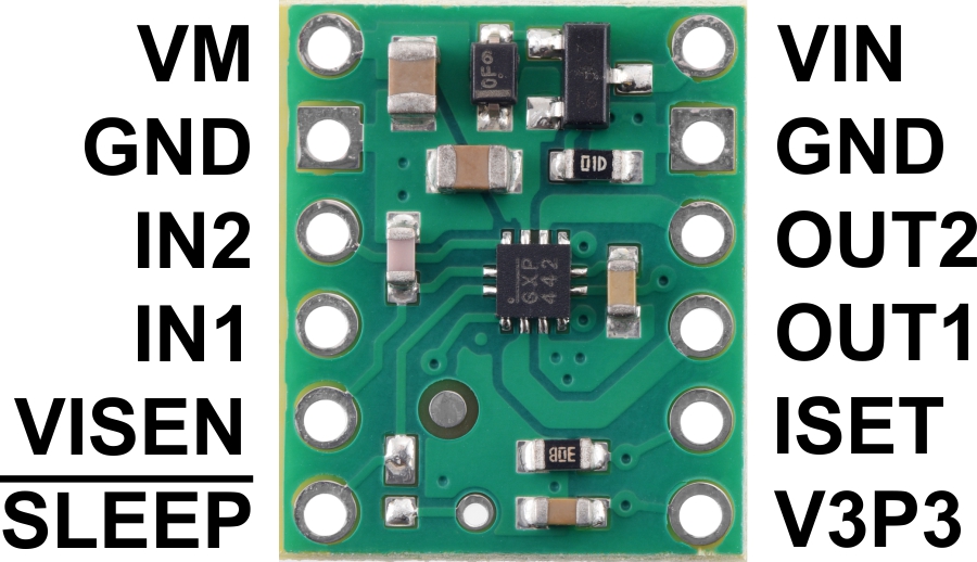 |
| PIN | Default State | Description |
|---|---|---|
| VIN | 1.8 V to 22 V board power supply input (reverse-protected up to 20 V). | |
| GND | Ground connection points for the motor and logic supplies. The control source and the motor driver must share a common ground. | |
| VM | This pin gives access to the motor power supply after the reverse-voltage protection MOSFET (see the board schematic below). It can be used to supply reverse-protected power to other components in the system. | |
| OUT1 | Motor output 1. | |
| OUT2 | Motor output 2. | |
| IN1 | LOW | Control input 1. PWM can be applied to this pin. |
| IN2 | LOW | Control input 2. PWM can be applied to this pin. |
| SLEEP | LOW | Sleep input that puts the MP6550 into a low-power sleep mode when low. By default, this pin is only connected to the nSLEEP_HB pin on the MP6550. It can also be connected to the nSLEEP_LDO pin to control the 3.3V LDO by bridging the nSLEEP surface mount jumper (see below). |
| ISET | Current sensing and current limiting configuration pin. A 2 kO resistor is connected from this pin to ground (see below). | |
| VISEN | Current sense output. This pin provides an analog current-sense feedback voltage of 200 mV/A by default (see below). | |
| V3P3 | 3.3 V regulator output. Disabled by default (see below). |
SLEEP pin and 3.3 V LDO
The board’s SLEEP pin is connected to the nSLEEP_HB pin on the MP6550, which is internally pulled low, disabling the H-bridge and putting the driver into a low-power sleep mode. This can be used to conserve power when the device is not in use. Driving SLEEP high enables the driver.
The MP6550 has an internal 3.3 V low-dropout (LDO) regulator, although it is not enabled by default since the chip’s nSLEEP_LDO pin, which controls the regulator, is also internally pulled low. (The LDO does not need to be enabled for the rest of the driver to function.) By default, nSLEEP_LDO is not connected to anything on the carrier board, but by shorting the surface mount jumper shown in the picture below, nSLEEP_LDO can be tied to the board’s SLEEP pin. This allows the LDO to be enabled along with the rest of the driver when SLEEP is high. When enabled, the 3.3V regulator can supply up to 50 mA of current through the V3P3 pin.
 |
nSLEEP_HB to nSLEEP_LDO jumper on the MP6550 Single Brushed DC Motor Driver Carrier. |
|---|
Current sensing and current limiting
The MP6550 can sense the motor current and actively limit it by using constant-off-time PWM current regulation (current chopping). The feedback sensitivity and current limiting threshold are set by a resistance connected between the ISET pin and ground. The carrier board is populated with a 2 kO pull-down resistor on ISET, which makes the VISEN pin output a voltage of 200 mV/A and limits the current to 2.5 A by default. This behavior can be customized by adding an external pull-down resistor to the ISET pin in parallel with the one already on the carrier. This will reduce the overall resistance, increasing the current limit and decreasing the VISEN sensitivity. If you want to reduce the current limit and increase the VISEN sensitivity, you would need to remove the surface mount resistor and replace it with a surface mount or external resistor of a larger value. Refer to the MP6550 datasheet for more information about the driver’s current sensing and current limiting.
Real-world power dissipation considerations
The MP6550 datasheet recommends a maximum continuous current of 2 A. However, the chip by itself will typically overheat at lower currents. In Pololu's tests, Pololu found that for most combinations of logic (VCC) and motor supply (VIN) voltages, the chip was able to deliver 2 A for between 30 seconds and a few minutes before the chip’s thermal protection kicked in and disabled the motor outputs; a continuous current of 1.7 A was sustainable for many minutes without triggering a thermal shutdown.
The actual current you can deliver will depend on how well you can keep the motor driver cool. The carrier’s printed circuit board is designed to help with this by drawing heat out of the motor driver chip. Pololu's tests were conducted at 100% duty cycle with no forced air flow; PWMing the motor will introduce additional heating proportional to the frequency.
This product can get hot enough to burn you long before the chip overheats. Take care when handling this product and other components connected to it.
Schematic
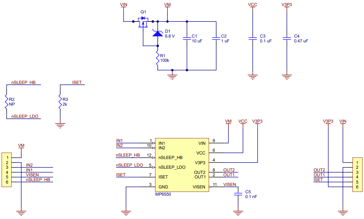 |
Schematic diagram for the MP6550 Single Brushed DC Motor Driver Carrier. |
|---|
This schematic is also available as a downloadable pdf (90k pdf).
Dimensions
| Size: | 0.5" × 0.6" |
|---|---|
| Weight: | 0.5 g1 |
General specifications
| Motor driver: | MP6550 |
|---|---|
| Motor channels: | 1 |
| Minimum operating voltage: | 1.8 V |
| Maximum operating voltage: | 22 V |
| Continuous output current per channel: | 1.7 A |
| Peak output current per channel: | 2.5 A2 |
| Current sense: | 0.2 V/A3 |
| Maximum PWM frequency: | 100 kHz |
| Minimum logic voltage: | 1.8 V |
| Maximum logic voltage: | 5 V |
| Reverse voltage protection?: | Y4 |
| Header pins soldered?: | N |
Identifying markings
| PCB dev codes: | md44a |
|---|---|
| Other PCB markings: | 0J13903 |
Notes:
- 1
- Without included hardware.
- 2
- Default current limit determined by on-board configuration resistor.
- 3
- Determined by on-board configuration resistor.
- 4
- Note: Reverse voltage protection only works up to 20 V.
File downloads
-
Schematic diagram for the MP6550 Single Brushed DC Motor Driver Carrier (90k pdf)
-
MPS MP6550 motor driver datasheet (714k pdf)
-
Dimension diagram of the MP6550 Single Brushed DC Motor Driver Carrier (274k pdf)
-
3D model of the MP6550 Single Brushed DC Motor Driver Carrier (3MB step)
-
Drill guide for the MP6550 Single Brushed DC Motor Driver Carrier (14k dxf)
This DXF drawing shows the locations of all of the board’s holes.
Recommended links
Exact shipping can be calculated on the view cart page (no login required).
Products that weigh more than 0.5 KG may cost more than what's shown (for example, test equipment, machines, >500mL liquids, etc).
We deliver Australia-wide with these options (depends on the final destination - you can get a quote on the view cart page):
- $3+ for Stamped Mail (typically 10+ business days, not tracked, only available on selected small items)
- $7+ for Standard Post (typically 6+ business days, tracked)
- $11+ for Express Post (typically 2+ business days, tracked)
- Pickup - Free! Only available to customers who live in the Newcastle region (must order online and only pickup after we email to notify you the order is ready). Orders placed after 2PM may not be ready until the following business day.
Non-metro addresses in WA, NT, SA & TAS can take 2+ days in addition to the above information.
Some batteries (such as LiPo) can't be shipped by Air. During checkout, Express Post and International Methods will not be an option if you have that type of battery in your shopping cart.
International Orders - the following rates are for New Zealand and will vary for other countries:
- $12+ for Pack and Track (3+ days, tracked)
- $16+ for Express International (2-5 days, tracked)
If you order lots of gear, the postage amount will increase based on the weight of your order.
Our physical address (here's a PDF which includes other key business details):
40 Aruma Place
Cardiff
NSW, 2285
Australia
Take a look at our customer service page if you have other questions such as "do we do purchase orders" (yes!) or "are prices GST inclusive" (yes they are!). We're here to help - get in touch with us to talk shop.
Have a product question? We're here to help!
 PiicoDev Real Time Clock (RTC) RV-3028SKU: CE08239 Brand: PiicoDev
Accurate timekeeping, even during a power outage.
-
- Solderless Breadboard Jumper Cable Wires (75 Pieces)SKU: CE00301 Brand: Core ElectronicsThese jumper wires feature a male pin at each end which is perfect for connectin ...
- NPN Transistor (2N3904)SKU: CE05245 Brand: Core ElectronicsTransistors Bipolar - BJT NPN Transistor General Purpose (200mA).


- VGA OV7670 Camera Module I2C 640X480SKU: 018-DB-OV7670 Brand: Core ElectronicsA VGA Camera Module designed to easily interface with microcontrollers.
- UBEC DC/DC Step-Down (Buck) Converter - 5V @ 3A outputSKU: ADA1385 Brand: AdafruitYour power supply problems just got SOLVED! This little circuit board may look t ...
- Micro Metal Gearmotor 50:1SKU: FIT0094 Brand: DFRobotThis motor has a long (0.365" or 9.27 mm), D-shaped metal output shaft that matc ...
- Pololu Ball Caster with 1/2" Metal BallSKU: POLOLU-953 Brand: PololuThis ball caster uses a 1/2" diameter metal ball. The height of the assembled ki ...


Videos
View AllGuides

The Maker Revolution

Motor Drivers vs. Motor Controllers
Projects

UNITRAC

Racing Simulator Motion Platform

Makers love reviews as much as you do, please follow this link to review the products you have purchased.
Product Comments