


Magnetic Encoder Pair Kit for Mini Plastic Gearmotors, 12 CPR, 2.7-18V
Available with a lead time
Expect dispatch between Jul 20 and Jul 22
Quantity Discounts:
- 10+ $14.62 (exc GST)
- 25+ $14.16 (exc GST)
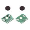
This kit includes two dual-channel Hall effect sensor boards and two 6-pole magnetic discs that can be used to add quadrature encoding to two mini plastic gearmotors with extended back shafts (motors are not included with this kit). The encoder board senses the rotation of the magnetic disc and provides a resolution of 12 counts per revolution of the motor shaft when counting both edges of both channels. To compute the counts per revolution of the gearbox output shaft, multiply the gear ratio by 12.
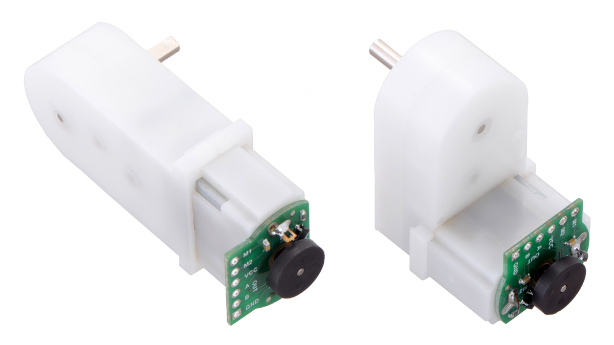 |
This compact encoder solution fits within the 11.5 mm × 22.5 mm cross section of the rear of the motors on three of the four sides. The fourth side of the encoder has the signal and power connections, and it extends 5 mm past the edge of the motor to leave room for mounting brackets. The assembly does not extend past the end of the extended motor shaft, which protrudes 5 mm beyond the back of the motor.
|
|


Note: This sensor system is intended for users comfortable with the physical encoder installation. It only works with mini plastic gearmotors that have extended motor shafts.
Pinout and installation
The encoder board is designed to be soldered directly to the back of the motor, with the back shaft of the motor protruding through the hole in the middle of the circuit board. One way to achieve good alignment between the board and the motor is to tack down the board to one motor pin and to solder the other pin only when the board is flat and well aligned. Be careful to avoid prolonged heating of the motor pins, which could deform the motor case or brushes. Once the board is soldered down to the two terminals, the motor leads are connected to the M1 and M2 pads along the edge of the board; the remaining four pads are used to power the sensors and access the two quadrature outputs:
|
|


The sensors are powered through the VCC and GND pins. VCC can be 2.7 V to 18 V, and the quadrature outputs A and B are digital signals that are either driven low (0 V) by the sensors or pulled to VCC through 10 kO pull-up resistors, depending on the applied magnetic field. The sensors’ comparators have built-in hysteresis, which prevents spurious signals in cases where the motor stops near a transition point.
 |
Encoder A and B outputs of a magnetic encoder on a high-power (HP) mini plastic gearmotor running at 4.5 V. |
|---|
The board’s six pads have a 0.1" (2.54 mm) pitch, so Pololu are compatible with common 0.1" connectors, or you can just solder individual wires directly to the board.
Once the board is soldered to the motor, the magnetic encoder disc can be pushed onto the motor shaft. One easy way to accomplish this is to press the motor onto the disc while it is sitting on a flat surface, pushing until the shaft makes contact with that surface. The size of the gap between the encoder disc and the sensor board does not have a big impact on performance as long as the motor shaft is at least all the way through the disc.
Schematic diagram
 |
This schematic is also available as a downloadable pdf (77k pdf).
People often buy this product together with:
 | 120:1 Mini Plastic Gearmotor, Offset 3mm D-Shaft Output, Extended Motor Shaft |
| 120:1 Mini Plastic Gearmotor HP, Offset 3mm D-Shaft Output, Extended Motor Shaft |
 | Pololu Mini Plastic Gearmotor Bracket Pair - Wide |
Dimensions
| Size: | 20 mm × 16.5 mm1 |
|---|---|
| Weight: | 2.4 g2 |
General specifications
| Minimum operating voltage: | 2.7 V |
|---|---|
| Maximum operating voltage: | 18 V |
Identifying markings
| PCB dev codes: | enc04a |
|---|---|
| Other PCB markings: | 0J9719 |
Notes:
- 1
- The assembled encoder will extend 5 mm beyond the back of the motor (it fits entirely within the length of the extended motor shaft).
- 2
- Weight of full set. Each encoder board weighs ~0.6 g and each magnet disc weighs ~0.6 g.
File downloads
-
Magnetic Encoder for Mini Plastic Gearmotors schematic diagram (77k pdf)
-
Dimension diagram of the Magnetic Encoder Pair Kit for Mini Plastic Gearmotors, 12 CPR, 2.7-18V (115k pdf)
-
3D models of Magnetic Encoder Pair Kit for Mini Plastic Gearmotors, 12 CPR, 2.7-18V (555k zip)
This file contains 3D models (in the step file format) of the components for the Magnetic Encoder Pair Kit for Mini Plastic Gearmotors, 12 CPR, 2.7-18V.
-
Drill guide for the enc04a encoder PCB (35k dxf)
This DXF drawing shows the locations of all of the board’s holes.
Exact shipping can be calculated on the view cart page (no login required).
Products that weigh more than 0.5 KG may cost more than what's shown (for example, test equipment, machines, >500mL liquids, etc).
We deliver Australia-wide with these options (depends on the final destination - you can get a quote on the view cart page):
- $3+ for Stamped Mail (typically 10+ business days, not tracked, only available on selected small items)
- $7+ for Standard Post (typically 6+ business days, tracked)
- $11+ for Express Post (typically 2+ business days, tracked)
- Pickup - Free! Only available to customers who live in the Newcastle region (must order online and only pickup after we email to notify you the order is ready). Orders placed after 2PM may not be ready until the following business day.
Non-metro addresses in WA, NT, SA & TAS can take 2+ days in addition to the above information.
Some batteries (such as LiPo) can't be shipped by Air. During checkout, Express Post and International Methods will not be an option if you have that type of battery in your shopping cart.
International Orders - the following rates are for New Zealand and will vary for other countries:
- $12+ for Pack and Track (3+ days, tracked)
- $16+ for Express International (2-5 days, tracked)
If you order lots of gear, the postage amount will increase based on the weight of your order.
Our physical address (here's a PDF which includes other key business details):
40 Aruma Place
Cardiff
NSW, 2285
Australia
Take a look at our customer service page if you have other questions such as "do we do purchase orders" (yes!) or "are prices GST inclusive" (yes they are!). We're here to help - get in touch with us to talk shop.
Have a product question? We're here to help!
 Breadboard-Friendly 3.5mm Stereo Headphone JackSKU: ADA1699 Brand: AdafruitPipe audio in or out of your project with this very handy breadboard-friendly au ...
- Magnetic Encoder Disc for Micro Metal Gearmotors, 12 CPRSKU: POLOLU-2599 Brand: PololuThese magnetic discs can be used with Pololu's micro metal gearmotors with exten ...
- Magnetic Encoder Pair Kit for Micro Metal Gearmotors, 12 CPR, 2.7-18V (HPCB compatible)SKU: POLOLU-3081 Brand: PololuAdd quadrature encoders to your micro metal gearmotors (extended back shaft vers ...
- 1 Channel Solid State Relay Module (DC Control, AC Load)SKU: CE05352 Brand: Core Electronics
This breakout module gives you access to a single channel solid state relay t ...


Guides

The Maker Revolution
Projects

The Rats Nest VCC Desktop Power Supply

Remote-Controlled Mars Rover

FlipperMate: Hands-Free Pinball

Makers love reviews as much as you do, please follow this link to review the products you have purchased.
Product Comments