Breakout Board for microSD Card
In stock, ships same business day if ordered before 2PM
Fastest delivery: Tomorrow*
Disclaimer:
For next-day delivery, the shipping address must
be in the AusPost next-day network, eParcel Express must be selected, and the order must be placed
before 2PM AEST Mon-Thurs excluding NSW Public Holidays. Orders may be delayed due to AusPost
pickup timings and order verifications. eParcel Express is typically a 1-day service within the
AusPost next-day network, though it is sometimes 2+ days.
Quantity Discounts:
- 10+ $7.25 (exc GST)
- 25+ $7.02 (exc GST)
 |
MicroSD memory cards (originally known as TransFlash) provide a compact and inexpensive way to add gigabytes of non-volatile storage to a project. All SD cards support communication over the SPI (Serial Peripheral Interface) bus, making it straightforward to interface one of these cards with an SPI-capable microcontroller.
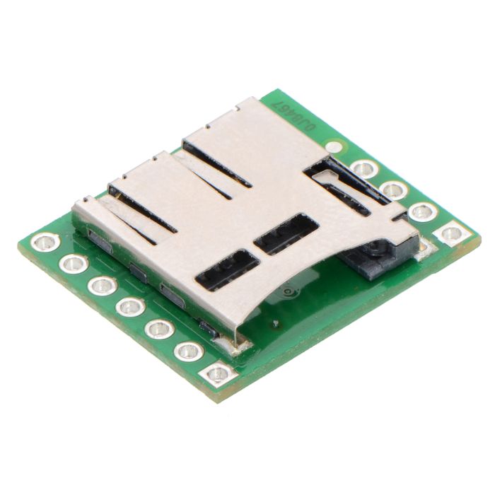
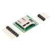
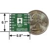
This carrier board makes it easy to connect to a microSD card by breaking out all of the contacts from a microSD card socket into two rows of 0.1"-spaced pins. The board measures only 0.8" × 0.7", and a set of breakaway 0.1" male header strips (one 1×7 and one 1×4) is included, which can be soldered in to use the board with breadboards, perfboards, or 0.1" female connectors. (The headers might ship as a single 1×11 piece that can be broken in two).
|
|
Pololu also carry a larger microSD card breakout board with a 3.3V regulator and level shifters that can be directly integrated into 5 V systems; it only breaks breaks out the more commonly used SPI bus mode interface pins, and it includes two mounting holes. The pictures below show the two versions side-by-side.
|
|
Using the breakout board
Since many microcontrollers have built-in SPI interfaces, most hobbyist projects communicate with Secure Digital cards in SPI bus mode. (The alternative SD bus mode is proprietary, and a license from the SD Association is required for access to the full specifications.) Where applicable, the pins on this board are labeled according to their functions in SPI mode.
All of the microSD card’s power pins and all of the signal pins necessary to interface with the card through SPI are available along the right side of the board. The left side of the board exposes duplicate power pins, along with two additional signal lines (DAT1 and DAT2) that are not needed for SPI communication but are used in 4-bit SD bus mode. The DAT1 pin also serves as an interrupt pin (IRQ) in SDIO devices. (Note that if you are using this module in a breadboard, you might want to solder header pins into both sides of the board for added stability even if you only plan to use the SPI pins.)
 |
The following tables describe the function of each pin on the breakout board in SPI and SD mode:
| Pin | Description | ||
|---|---|---|---|
| GND (VSS) |
Power and logic ground | ||
| VDD | Supply voltage (2.7 V to 3.6 V for standard microSD cards) | ||
| CD | Card detect. When a card is inserted, this pin is floating; when no card is inserted, it is shorted to ground. A pull-up resistor can be used to pull the line high when a card is present. | ||
| SPI mode | SD mode | ||
| Pin | Description | Pin | Description |
| DI | Data in (MOSI) | CMD | Command/response |
| DO | Data out (MISO) | DAT0 | Data (bit 0) |
| SCLK | Clock | CLK | Clock |
| CS | Chip select (active low) | DAT3 | Data (bit 3) |
| — IRQ |
Reserved Interrupt (active low; SDIO devices only) |
DAT1 IRQ |
Data (bit 1) Interrupt (active low; SDIO devices only) |
| — | Reserved | DAT2 | Data (bit 2) |
Warning: Standard microSD cards use 3.3 V logic level signals, so level shifters or voltage dividers are required when connecting one to a 5 V system.
Communicating with a microSD card
The SD Association publishes a set of simplified specifications for SD cards containing information on interfacing with them. However, there are a number of ways to get started without understanding the specifications or writing your own code from scratch, since many microcontroller development platforms provide libraries for communicating with SD cards. For example:
- The SD library for Arduino provides functions for accessing files and directories on an SD card. (It also works with Arduino-compatible boards like Pololu's A-Star programmable controllers.)
- The SD Card File System library for mbed allows similar filesystem access.
Schematic
 |
|
Breakout Board for microSD Card schematic diagram. |
|---|
This schematic is also available as a downloadable pdf (140k pdf).
Dimensions
| Size: | 0.8" × 0.7" × 0.12"1 |
|---|---|
| Weight: | 1.3 g2 |
Identifying markings
| PCB dev codes: | sdc01a |
|---|---|
| Other PCB markings: | 0J8467 |
Notes:
- 1
- Without a microSD card or the included optional header pins. When inserted, a microSD card will extend approximately 35 mil (0.85 mm) past the edge of the board.
- 2
- Without a microSD card or the included optional header pins.
File downloads
-
Breakout Board for microSD Card schematic diagram (140k pdf)
Printable schematic for the Breakout Board for microSD Card.
-
Drill guide for the Breakout Board for microSD Card (21k dxf)
This DXF drawing shows the locations of all of the board’s holes.
Recommended links
-
The SD Association’s simplified standard specifications for SD cards.
Exact shipping can be calculated on the view cart page (no login required).
Products that weigh more than 0.5 KG may cost more than what's shown (for example, test equipment, machines, >500mL liquids, etc).
We deliver Australia-wide with these options (depends on the final destination - you can get a quote on the view cart page):
- $3+ for Stamped Mail (typically 10+ business days, not tracked, only available on selected small items)
- $7+ for Standard Post (typically 6+ business days, tracked)
- $11+ for Express Post (typically 2+ business days, tracked)
- Pickup - Free! Only available to customers who live in the Newcastle region (must order online and only pickup after we email to notify you the order is ready). Orders placed after 2PM may not be ready until the following business day.
Non-metro addresses in WA, NT, SA & TAS can take 2+ days in addition to the above information.
Some batteries (such as LiPo) can't be shipped by Air. During checkout, Express Post and International Methods will not be an option if you have that type of battery in your shopping cart.
International Orders - the following rates are for New Zealand and will vary for other countries:
- $12+ for Pack and Track (3+ days, tracked)
- $16+ for Express International (2-5 days, tracked)
If you order lots of gear, the postage amount will increase based on the weight of your order.
Our physical address (here's a PDF which includes other key business details):
40 Aruma Place
Cardiff
NSW, 2285
Australia
Take a look at our customer service page if you have other questions such as "do we do purchase orders" (yes!) or "are prices GST inclusive" (yes they are!). We're here to help - get in touch with us to talk shop.
Have a product question? We're here to help!
Videos
View AllGuides
Identify Electrical Connectors
The Maker Revolution
Projects
Raspberry Pi Cyberdeck (SDR Edition)
Pico-Dog Motion Activated Audio Alarm
WaveJumper: Music Sample Slicer on a Breadboard
Makers love reviews as much as you do, please follow this link to review the products you have purchased.






Product Comments