This project began with a desire to make circuit building readily approachable for students new to electronics by bridging the gap between schematic diagrams and working circuits. The PiicoDev ecosystem provides a very accessible introduction to electronics, and Fritzing is a great tool for creating realistic-looking circuits. However, there were no realistic representations of PiicoDev components available. To address this, I created a set of custom Fritzing parts that visually replicate the physical PiicoDev modules, complete with virtual electrical connection points. This system expands on an existing system (see the great PiicoDev Schematic System created by Ezra224017) by creating a dedicated part for the PiicoDev Expansion Board that breaks out all pins. This feature enables designers of circuits to show connections to any pin on a Raspberry Pi Pico, not just the designated PiicoDev header pins (GP8 and GP9). This makes it possible to easily integrate both PiicoDev and non-PiicoDev products in a single visual diagram, and to make use of the second I2C bus (I2C1). Ultimately, this offers a simple and flexible tool for visually representing circuits that incorporate PiicoDev products.

What this project covers:
- Installing the Fritzing program
- Downloading and importing PiicoDev custom parts
- Creating circuit diagrams in Fritzing using custom PiicoDev parts
- Limitations of the system
- Examples using PiicoDev Fritzing parts in project design
Installing the Fritzing program
The Fritzing program can be downloaded from fritzing.org and installed on machines running Windows, macOS, or Linux. They do ask for a contribution to help fund further development. This is currently €8 (but I am sure they would happily accept more generous support).
Downloading and importing PiicoDev custom parts
I have placed the PiicoDev Fritzing parts I have created in a GitHub repository. I would suggest putting all the PiicoDev parts in a custom bin. Instructions for downloading the parts and importing them into Fritzing can be found in the README.md file in the GitHub repository. As of the writing of this project, the repository does not contain PiicoDev products that are specifically for the Raspberry Pi or micro:bit, but it does contain the build platform and expansion board for the Raspberry Pi Pico. The other parts will be added when complete.
Alternatively, the parts can be downloaded here.
Using Fritzing with PiicoDev custom parts
I have found the PiicoDev build platform, along with the PiicoDev expansion board, to be very useful for testing PiicoDev modules and prototyping ideas, particularly with students in a classroom. For this reason, I not only created Fritzing parts for the various PiicoDev modules, but also for the Raspberry Pi Pico build platform and expansion board. Another feature of the PiicoDev system is the cables used to connect the modules. I have also created parts to represent four-wire JST-SH connectors that link to the PiicoDev connectors on the modules.
Setting up the development space:
- With Fritzing open, select the Breadboard view and the parts bin where your parts are located. Mine are in a custom bin named “PiicoDev” marked with a Core Electronics icon (NOTE: your parts bin will likely look different than mine).
- The default breadboard is full-size. To make a half-size breadboard, be sure that the Inspector window is showing by clicking on the Window dropdown menu and selecting Inspector.
- In the Inspector window, scroll down to Properties and change the default full+ to half+. At this point, you can right-click (or equivalent) and choose to Add to bin… (I have my custom breadboard added to my PiicoDev bin).

Setting up the PiicoDev environment:
- Drag and place the PiicoDev pieces that you wish to use from the bin to the Breadboard view window.
- Select the appropriate JST connectors. One is labelled “upper” for modules that have the PiicoDev connector on the upper surface. The other is labelled “lower” for modules with the PiicoDev connector on the lower surface.
NOTE: pieces can be rotated by clicking on the rotation arrow at the bottom of the screen or right-clicking and selecting the “Rotate” option.

Wiring the pieces
- Place the JST connectors into position by aligning the connection points and matching the wire colours. The connections will not be made at this point.
- For JST connectors that are meant to appear below the board, right-click on the module, select Raise and Lower, then Bring to front. The connector will then appear below the module.
- Move the PiicoDev module slightly, then back into position until the connection points turn from red to green. Steps 7 and 8 are illustrated in the animated GIF. (NOTE: the connection points may not all appear connected, but if they are aligned properly and some of the four connection points are showing a connection, when you let go of the mouse button, they will be connected).
- It is a good idea at this point to “lock” all parts by right-clicking and selecting Lock Part. This will fix the part in position before you connect the wires. It is very easy to accidentally move parts while connecting wires.

- Connect wires by clicking and dragging from one connection point to the next.
- While the wire is still selected, change the colour by picking a color option in the Inspector window.
- Create bends in wires by clicking and dragging at any point on the wire.
- A Raspberry Pi Pico Fritzing part can be placed over the top of the expansion board to complete the diagram.

Limitations
There are a few limitations to the system.
- Fritzing has no four-wire cable systems that can be used to represent the PiicoDev cables.
- By default, the breadboard is always placed at the bottom of the image. The current version of the PiicoDev build platform has places for six PiicoDev modules. If a breadboard is used in the Fritzing circuit, these outlines will appear on top of the breadboard. If a breadboard is used, it is best to use the “3mod” version of the build platform. This is also the original PiicoDev build platform.
- I have not attempted to create parts that could be used to create PCBs or be used in simulations.
Using Fritzing parts in project design
Below, I outline two project applications using the PiicoDev Fritzing parts to illustrate how easy it would be for students to follow the diagram to recreate the circuits. The first application is the creation of a prototype for an intruder alarm system. The second application is demonstrating the use of two colour sensors with identical I2C addresses by taking advantage of the two I2C buses available on the Raspberry Pi Pico.
Project Application 1: A prototype of an intruder alarm system
The purpose of this project application is to illustrate the use of the PiicoDev Fritzing parts in a simple project that might be suitable in a classroom environment. The application illustrated is the creation of a prototype of a simple intruder alarm system. It uses:
- Raspberry Pi Pico
- PiicoDev platform for Raspberry Pi Pico
- PiicoDev expansion board for Pico
- PiicoDev OLED display module
- PiicoDev buzzer module
- PiicoDev 3x RGB LED module
- PiicoDev capacitive touch sensor
- PiicoDev ultrasonic rangefinder (including RCWL-1601 ultrasonic sensor)
- PiicoDev cables (x5)
- 2.5M screws, risers, and nuts as needed to attach parts (I used 14 risers, 34 screws, and 4 nuts). These can be found at Core Electronics (White Nylon Screw and Stand-off Set – M2.5 Thread)

The build
The project can be assembled using the Fritzing diagram shown. The capacitive touch sensor is used as a way of generating a unique trigger to activate or deactivate the alarm system. The ultrasonic sensor is used to detect the presence of an object within a given distance. The OLED display is used to provide written information. The LEDs provide visual signals, while the buzzer provides audible signals.
The code
The example code will work for the given prototype, but if used in a classroom, it would be beneficial to scaffold code development by having students generate code specific to each component before putting it together into a whole.
# –----Intruder alarm system-----

from machine import Pin
from PiicoDev_RGB import PiicoDev_RGB
from PiicoDev_Unified import sleep_ms
from PiicoDev_Ultrasonic import PiicoDev_Ultrasonic
from PiicoDev_Buzzer import PiicoDev_Buzzer
from PiicoDev_CAP1203 import PiicoDev_CAP1203
from PiicoDev_SSD1306 import *

# ---Define constants---
ALARM_DISTANCE = 500    # mm threshold for triggering alarm
LED_COUNT = 3           # valid values are 0-3
BRIGHTNESS_NORMAL = 127
BRIGHTNESS_MAX = 255

# ---Define colours---
RED    = [255, 0, 0]
GREEN  = [0, 255, 0]
BLUE   = [0, 0, 255]
YELLOW = [255, 255, 0]
WHITE  = [255, 255, 255]

# ---Hardware setup---
buzzer = PiicoDev_Buzzer()
ranger = PiicoDev_Ultrasonic()
touch_sensor = PiicoDev_CAP1203()
display = create_PiicoDev_SSD1306(
    address=0x3C, bus=0, sda=Pin(8), scl=Pin(9)
)
leds = PiicoDev_RGB(
    bus=0, sda=Pin(8), scl=Pin(9), freq=400000, bright=BRIGHTNESS_NORMAL
)

# ---Helper function definitions---
def set_all_leds(color, brightness=None):
    """Set all LEDs to the same colour, optional brightness."""
    if brightness is not None:
        leds.setBrightness(brightness)
    for i in range(LED_COUNT):
        leds.setPixel(i, color)
    leds.show()

def display_text(lines, clear=True):
    """Show one or more lines of text on the OLED."""
    if clear:
        display.fill(0)
    for i, text in enumerate(lines):
        display.text(text, 20, 20 + i*10, 1)
    display.show()

# ---Activation wait---
status = touch_sensor.read()
while status[2] == 0:  # Touch pad 2 activates system
    status = touch_sensor.read()
    display_text(["Touch code", "to activate"])
    set_all_leds(GREEN, BRIGHTNESS_NORMAL)

# ---Main loop---
while True:
    status = touch_sensor.read()

    if not (status[1] and status[3]):  # Press pads 1 & 3 simultaneously to stop system
        # System active
        set_all_leds(BLUE, BRIGHTNESS_NORMAL)

        dist = ranger.distance_mm
        display_text([f"Distance:", f"{dist} mm"])

        # Intruder detected
        if dist < ALARM_DISTANCE:
            display_text(["INTRUDER!"])
            set_all_leds(WHITE, BRIGHTNESS_MAX)
            buzzer.tone(800, 500)
            sleep_ms(500)
            buzzer.tone(400, 500)
            set_all_leds(RED)
            sleep_ms(1500)
            leds.clear()
    else:
        break  # System shutdown initiated

# ---Shutdown sequence---
leds.clear()
display.fill(0); display.show()

for step in range(5):
    brightness = BRIGHTNESS_MAX - 50 * (step + 1)
    set_all_leds(YELLOW, brightness)
    display_text(["System", "shutdown"])
    sleep_ms(1500)

    display.fill(0); display.show()
    sleep_ms(200)

leds.clear()
Extension - from prototype to product
In a classroom, students could be encouraged to extend this project. For example, students could add additional ultrasonic sensors and use the I2C address switch built into the PiicoDev module so as not to create address clashes, or students could attach the ultrasonic sensor to a servo motor so it scans its environment for intruders. They could also be challenged to design a case or mounting for the project using 3D printing, laser cutting, or even a cardboard box.
Project Application 2: Colour detection using two colour sensors
The purpose of this project application is to demonstrate the use of the Fritzing parts to connect to the Raspberry Pi Pico in ways other than through the PiicoDev port connected to the expansion board. To do this, I have used the PiicoDev Fritzing parts to set up a test using two PiicoDev colour sensors, which have the same I2C address and no switch to change addresses.
This requires the use of two different I2C buses. It uses:
- Raspberry Pi Pico
- PiicoDev platform for Raspberry Pi Pico
- PiicoDev expansion board for Pico
- PiicoDev OLED display module
- PiicoDev colour sensor (x2)
- PiicoDev cables (x2)
- PiicoDev prototyping cable (male) 200 mm
- 2.5M screws, risers, and nuts as needed to attach parts (I used 10 risers and 20 screws)
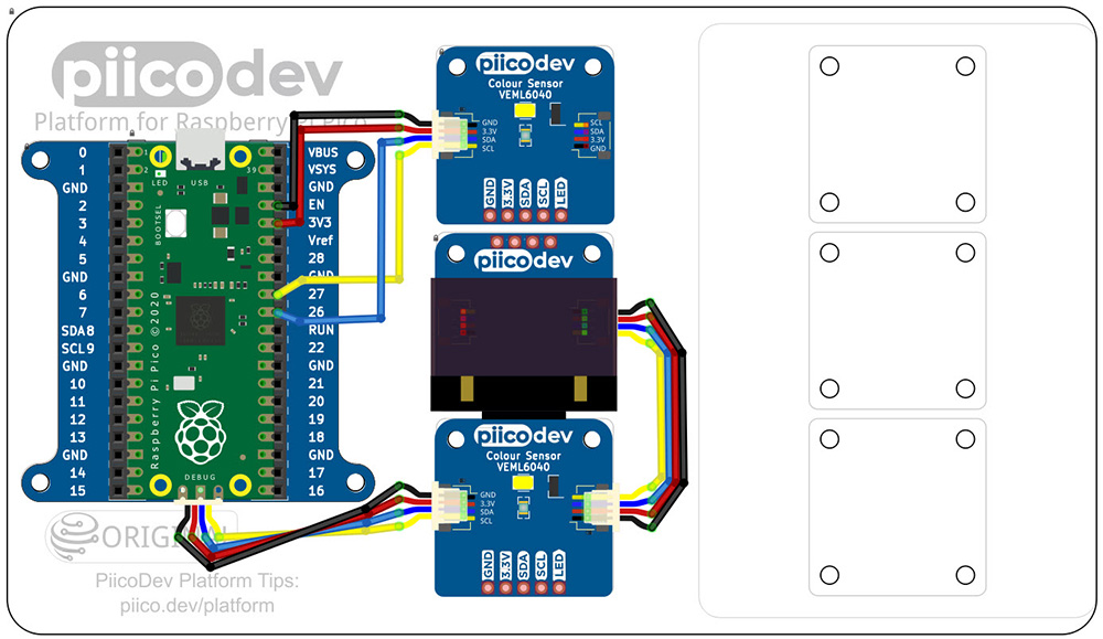
The build
The project can be assembled using the Fritzing diagram shown. One of the colour sensors is connected to I2C bus 0 (GP8 and GP9) via the PiicoDev cable. The other colour sensor is connected to I2C bus 1 via a PiicoDev prototyping cable connected directly to SDA and SCL pins through the expansion board.
The code
The example code will work for the given prototype, but if used in a classroom, it would be beneficial to scaffold code development by having students generate code specific to each component before putting it together into a whole.
# –----Two sensor colour detection-----

# Reads data from two PiicoDev VEML6040 colour sensors
# Each is connected to a different I2C bus
# Raw data RGB data is displayed on OLED and printed to console

from machine import Pin
from PiicoDev_VEML6040 import PiicoDev_VEML6040
from PiicoDev_SSD1306 import *
from time import sleep

# ---Define constants---
NUM_READS = 50
SCALE = 100  # Divisor to scale RGB values to fit on OLED

# ---Hardware setup---
display = create_PiicoDev_SSD1306()
sensors = [
    PiicoDev_VEML6040(bus=1, sda=Pin(2), scl=Pin(3), freq=400000),
    PiicoDev_VEML6040(bus=0, sda=Pin(8), scl=Pin(9), freq=400000),
    ]

# ---Function definitions---
def read_rgb(sensor, scale=SCALE):
    """Read RGB values from sensor and return scaled integers."""
    data = sensor.readRGB()
    return tuple(int(round(data[c]/scale, 0)) for c in ('red', 'green', 'blue'))

# ---Main loop---
for _ in range(NUM_READS):
    display.fill(0)  # clear screen
    display.text("S   R   G   B", 0, 0, 1)

    for i, sensor in enumerate(sensors, start=1):
        # Write to OLED
        r, g, b = read_rgb(sensor)
        display.text(f"{i}  {r}  {g}  {b}", 0, 20*i, 1)
        # Write to console (RGB)
        print(f"Sensor {i}: R={r} G={g} B={b}")

    display.show()
    sleep(1)

# Clear OLED
display.fill(0)
display.show()

