
A4990 Dual Motor Driver Carrier
Available with a lead time
Expect dispatch between Jul 29 and Aug 03
Quantity Discounts:
- 10+ $20.42 (exc GST)
- 25+ $19.78 (exc GST)
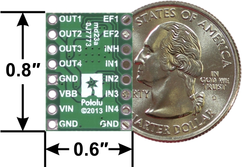 |
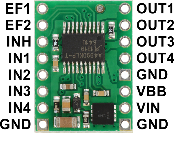
A4990 dual motor driver carrier, bottom view with dimensions. |
|---|
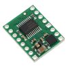
Allegro’s A4990 is a dual H-bridge motor driver IC that can be used for bidirectional control of two brushed DC motors at 6 V to 32 V. It can supply up to 0.7 A continuously to each motor channel, and the current control feature of the A4990 limits the peak motor current to about 0.9 A per channel with the onboard sense resistors, making this a good choice for small, low-current motors that run on relatively high voltages. Since this board is a carrier for the A4990, Pololu recommend careful reading of the A4990 datasheet (301k pdf). The board ships populated with all of its SMD components, including the A4990 and an additional FET for reverse battery protection.
For a single-channel driver with a DIR/PWM interface and a similar operating voltage range, please consider Pololu's DRV8801 carrier. For lower-voltage alternatives to the A4990, consider Pololu's DRV8833 and DRV8835 dual motor driver carriers.
Pololu also carry an A4990 dual motor driver Arduino shield that makes it easy to incorporate this great driver into an Arduino project.
Features
- Dual-H-bridge motor driver: can drive two DC motors or one bipolar stepper motor
- Operating voltage: 6?? V to 32 V1
- Output current: 0.7 A continuous per motor
- Current control limits peak current to 0.9 A per motor
- Inputs are 3V- and 5V-compatible
- Robust:
- Reverse-voltage protection circuit
- Can survive input voltages up to 40 V2
- Under-voltage and over-voltage protection
- Over-temperature protection
- Short-to-supply, short-to-ground, and shorted-load protection on the motor outputs
1 Over-voltage protection typically kicks in at 34 V, but it can trigger at voltages as low as 32 V.
2 While the A4990 can tolerate input voltages as high as 50 V, the reverse-voltage protection MOSFET is only rated for 40 V.
Using the motor driver
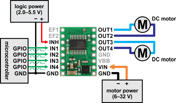 |
Minimal wiring diagram for connecting a microcontroller to an A4990 dual motor driver carrier. |
|---|
In a typical application, power connections are made on one side of the board and control connections are made on the other. The INH (inhibit) pin is pulled low internally, disabling the A4990 by default, and must be driven high (2.0–5.5 V) in order to enable the driver.
The OUT1 and OUT2 pins form one motor channel while the OUT3 and OUT4 pins form the other. The state of each output is controlled by a corresponding input (IN1 through IN4); note that IN2 and IN4 are inverted inputs. All four INx pins are pulled to their inactive states by default. See the truth tables in the A4990 datasheet for more information on how the inputs affect the driver outputs.
The EF1 and EF2 pins are open-drain outputs that are driven low by the chip to indicate active faults (the datasheet describes what each combination of EF1 and EF2 means). Otherwise, these pins remain in a floating state, so you will need to connect external pull-up resistors (or use microcontroller inputs with their built-in pull-ups enabled) if you want to monitor fault conditions on the driver.
Pinout
 |
| PIN | Default State | Description |
|---|---|---|
| VIN | Reverse-protected 6 V to 32 V motor power supply connection. | |
| VBB | This pin gives access to the motor power supply after the reverse-voltage protection MOSFET (see the board schematic below). It can be used to supply reverse-protected power to other components in the system. It is generally intended as an output, but it can also be used to supply board power. | |
| GND | Ground connection points for the motor and logic power supplies. The control source and the motor driver must share a common ground. | |
| OUT1 | Motor A output +. | |
| OUT2 | Motor A output -. | |
| OUT3 | Motor B output +. | |
| OUT4 | Motor B output -. | |
| IN1 | LOW | Control input for OUT1. PWM can be applied to this pin. |
| IN2 | HIGH | Inverted control input for OUT2. PWM can be applied to this pin. |
| IN3 | LOW | Control input for OUT3. PWM can be applied to this pin. |
| IN4 | HIGH | Inverted control input for OUT4. PWM can be applied to this pin. |
| INH | LOW | Logic input that puts the A4990 into a low-power sleep mode when low. |
| EF1 | floating | Error flag output 1: driven low to indicate active fault status; floating otherwise. |
| EF2 | floating | Error flag output 2: driven low to indicate active fault status; floating otherwise. |
Current limiting
The A4990 can actively limit the current through the motors by using a fixed-frequency PWM current regulation (current chopping). This carrier board connects 0.075 O resistors to the current sense pins, which sets the current limit to a nominal 1 A per channel. In Pololu's tests, the board actually limited the motor current to slightly above 0.9 A.
Real-world power dissipation considerations
Even though the driver limits the motor current to about 0.9 A per channel, the chip by itself will overheat at lower currents. For example, in Pololu's tests at room temperature with no forced air flow, the chip was able to deliver 0.9 A per channel for approximately 20 s before the chip’s thermal protection kicked in. A continuous current of 0.7 A per channel was sustainable for many minutes without triggering a thermal shutdown. The actual current you can deliver will depend on how well you can keep the motor driver cool. The carrier’s printed circuit board is designed to draw heat out of the motor driver chip, but performance can be improved by adding a heat sink. Pololu's tests were conducted at 100% duty cycle; PWMing the inputs will introduce additional heating proportional to the frequency (unless the A4990 is already PWMing the outputs to limit the current).
This product can get hot enough to burn you long before the chip overheats. Take care when handling this product and other components connected to it.
Included hardware
|
|
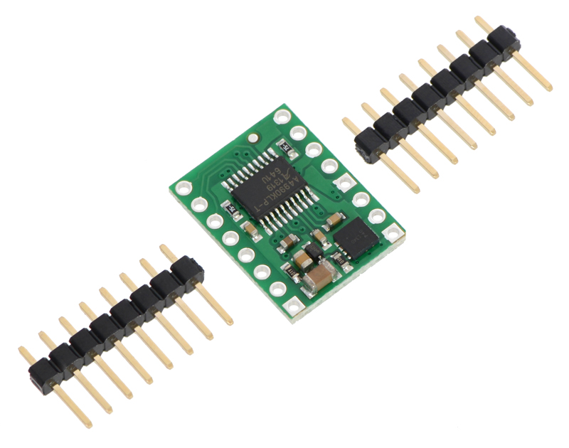
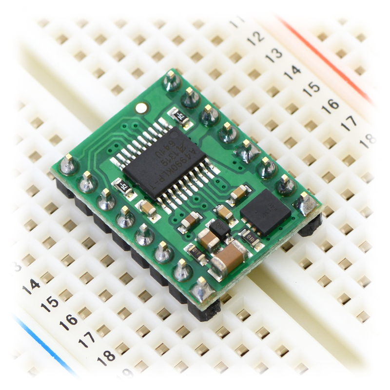
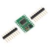
Two 1×8-pin breakaway 0.1" male headers are included with the A4990 motor driver carrier, which can be soldered in to use the driver with perfboards, breadboards, or 0.1" female connectors. (The headers might ship as a single 1×16 piece that can be broken in half.) When used with these header pins, the board can be oriented with the parts visible, as shown in the right picture above, or with the silkscreen visible, by soldering the headers in from the opposite side. You can also solder your motor leads and other connections directly to the board.
Schematic
 |
A4990 Dual Motor Driver Carrier schematic diagram. |
|---|
This schematic is also available as a downloadable pdf (118k pdf).
People often buy this product together with:
 | TB6612FNG Dual Motor Driver Carrier |
 | DRV8835 Dual Motor Driver Carrier |
 | DRV8801 Single Brushed DC Motor Driver Carrier |
Dimensions
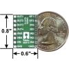
| Size: | 0.6" × 0.8"1 |
|---|---|
| Weight: | 0.8 g1 |
General specifications
| Motor driver: | A4990 |
|---|---|
| Motor channels: | 2 |
| Minimum operating voltage: | 6 V |
| Maximum operating voltage: | 32 V2 |
| Continuous output current per channel: | 0.7 A3 |
| Peak output current per channel: | 0.9 A4 |
| Reverse voltage protection?: | Y |
Identifying markings
| PCB dev codes: | md23a |
|---|---|
| Other PCB markings: | 0J7773 |
Notes:
- 1
- Without included hardware.
- 2
- Over-voltage protection typically activates at 34 V, but it can trigger at voltages as low as 32 V.
- 3
- Typical results with 100% duty cycle at room temperature.
- 4
- Current is automatically limited to this by the driver; determined by onboard sense resistors.
File downloads
-
A4990 datasheet (301k pdf)
Datasheet for the Allegro A4990 dual full bridge motor driver IC.
-
A4990 Dual Motor Driver Carrier schematic diagram (118k pdf)
Printable schematic diagram of the A4990 Dual Motor Driver Carrier.
-
Dimension diagram of the A4990 Dual Motor Driver Carrier (226k pdf)
-
Drill guide for the A4990 Dual Motor Driver Carrier (33k dxf)
This DXF drawing shows the locations of all of the board’s holes.
Exact shipping can be calculated on the view cart page (no login required).
Products that weigh more than 0.5 KG may cost more than what's shown (for example, test equipment, machines, >500mL liquids, etc).
We deliver Australia-wide with these options (depends on the final destination - you can get a quote on the view cart page):
- $3+ for Stamped Mail (typically 10+ business days, not tracked, only available on selected small items)
- $7+ for Standard Post (typically 6+ business days, tracked)
- $11+ for Express Post (typically 2+ business days, tracked)
- Pickup - Free! Only available to customers who live in the Newcastle region (must order online and only pickup after we email to notify you the order is ready). Orders placed after 2PM may not be ready until the following business day.
Non-metro addresses in WA, NT, SA & TAS can take 2+ days in addition to the above information.
Some batteries (such as LiPo) can't be shipped by Air. During checkout, Express Post and International Methods will not be an option if you have that type of battery in your shopping cart.
International Orders - the following rates are for New Zealand and will vary for other countries:
- $12+ for Pack and Track (3+ days, tracked)
- $16+ for Express International (2-5 days, tracked)
If you order lots of gear, the postage amount will increase based on the weight of your order.
Our physical address (here's a PDF which includes other key business details):
40 Aruma Place
Cardiff
NSW, 2285
Australia
Take a look at our customer service page if you have other questions such as "do we do purchase orders" (yes!) or "are prices GST inclusive" (yes they are!). We're here to help - get in touch with us to talk shop.
Have a product question? We're here to help!
 FireBeetle Board-328P with BLE4.1SKU: DFR0492 Brand: DFRobotDFRobot FireBeetle series are low power consumption microcontrollers designed fo ...
- Waterproof Cable Gland PG-7 Size (Black)SKU: FIT0727 Brand: DFRobotWaterproof is always a critical point for outdoor projects, and when you need to ...
- M1 EnclosureSKU: CE09942 Brand: ParticleThe versatile Monitor One IP67 enclosure now for the deployment of Particle's Ta ...
- Crystal Oscillator - 32.768KHzSKU: 002-815-AB38T-32-768KHZ Brand: Core ElectronicsGreat for use with the DS1307.


- Logic Level Shifter, 4-Channel, BidirectionalSKU: POLOLU-2595 Brand: PololuThis tiny logic level shifter features four bi-directional channels, allowing fo ...
- Breakout for JST SH-Style Connector, 6-Pin Male Side-Entry (3-Pack, Untested)SKU: POLOLU-4773 Brand: PololuThis simple board serves as an adapter between a JST SH-style 6-pin male connect ...
- 210:1 Micro Metal Gearmotor HPCB 12V with 12 CPR Encoder, Side ConnectorSKU: POLOLU-5221 Brand: PololuThis is a miniature brushed DC metal gearmotor with a gearbox cross section of 1 ...
- Breakout for JST SH-Style Connector, 5-Pin Male Side-Entry (2-Pack)SKU: POLOLU-4817 Brand: PololuThese simple boards serve as adapters between a JST SH-style 5-pin male connecto ...


Guides

The Maker Revolution
Projects

The Rats Nest VCC Desktop Power Supply

Remote-Controlled Mars Rover

FlipperMate: Hands-Free Pinball

Makers love reviews as much as you do, please follow this link to review the products you have purchased.
Product Comments