
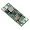


4.5-20V Fine-Adjust Step-Up Voltage Regulator U3V70A
In stock, ships same business day if ordered before 2PM
Fastest delivery: Tomorrow*
Disclaimer:
For next-day delivery, the shipping address must
be in the AusPost next-day network, eParcel Express must be selected, and the order must be placed
before 2PM AEST Mon-Thurs excluding NSW Public Holidays. Orders may be delayed due to AusPost
pickup timings and order verifications. eParcel Express is typically a 1-day service within the
AusPost next-day network, though it is sometimes 2+ days.
Quantity Discounts:
- 10+ $38.66 (exc GST)
- 25+ $37.45 (exc GST)
 |
The U3V70x boost (step-up) voltage regulators are high-current, high-efficiency synchronous switching regulators that generate higher output voltages from input voltages as low as 2.9 V. The regulators actively limit the instantaneous input currents to 10 A, and the input current can typically be as high as 8 A for several seconds before the thermal protection activates. Input currents of around 6 A can typically be maintained for many minutes without triggering thermal shutdown, though the actual performance depends on depending on the input and output voltages as well as external factors such as ambient temperature and airflow. For boost regulators, the output current equals the input current times the efficiency times the ratio of VIN to VOUT, so the more you are boosting, the lower the maximum output current will be (see the Typical efficiencies and output currents section below for performance graphs).
These regulators feature a variety of built-in protections, including reverse voltage protection to keep your load safe in the event power is accidentally connected backward, and unlike most boost regulators, these units offer a true shutdown option that turns off power to the load (with typical boost regulators, the input voltage will pass directly through to the output when they are disabled).
The U3V70x family includes six versions with fixed output voltages ranging from 5 V to 15 V as well as an adjustable version that can be set anywhere between 4.5 V and 20 V using a precision 12-turn potentiometer:
- U3V70F5: Fixed 5V output
- U3V70F6: Fixed 6V output
- U3V70F7: Fixed 7.5V output
- U3V70F9: Fixed 9V output
- U3V70F12: Fixed 12V output
- U3V70F15: Fixed 15V output
- U3V70A: Precision-adjustable 4.5 – 20 V output
The different versions of the board all look very similar, so the bottom silkscreen includes a blank space where you can add your own distinguishing marks or labels.
Pololu manufacture these boards in-house at Pololu's Las Vegas facility, which gives Pololu the flexibility to make these regulators with custom fixed output voltages between 4.5 V and 20 V. If you are interested in customization, please contact us.
Details for item #2890
Features and specifications
- Input voltage: 2.9 V to VOUT
- Output voltage: 4.5 V to 20 V (precision-adjustable using built-in 12-turn potentiometer)
- True shutdown option turns off power to the load
- Typical efficiency of 80% to 95%, depending on input voltage, output voltage, and load (see the Typical efficiencies and output currents section below for performance graphs)
- 10 A switch allows for:
- Instantaneous input currents up to 10 A
- Input currents up to 8 A for several seconds
- Input currents around 6 A to 7 A for prolonged durations, depending on input voltage and output voltage
- low quiescent current for most combinations of input and output voltages (see the quiescent current graph below for more details)
- Integrated protections:
- Reverse voltage protection
- Short-circuit protection with hiccup recovery
- Over-temperature shutoff
- Under-voltage lockout (typical thresholds are 2.4 V falling, 2.8 V rising)
- Cycle-by-cycle input current limiting to 10 A
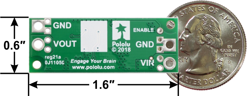
- Compact size: 1.6" × 0.6" × 0.22" (40.6 × 15.2 × 5.5 mm)
- Weight: 3.9 g
- Two mounting holes for #2 or M2 screws
- Smaller holes for 0.1" header pins and larger holes for terminal blocks offer several options for connecting to the board
U3V70A connections
 |
The input voltage, VIN, must be at least 2.9 V and should not exceed the output voltage, VOUT. (If VIN is higher than VOUT, the higher input voltage will show up on the output, which is potentially dangerous for your connected load and could also damage the regulator.)
The regulator is enabled by default: a 100 kO pull-up resistor on the board connects the ENABLE pin to reverse-protected VIN. The ENABLE pin can be driven low (under 0.4 V) to turn off power to the load and put the board into a low-power state. The typical no-load quiescent current is less than 1 mA (see the quiescent current graph below for more details).
Setting the output voltage
 |
The output voltage of the regulator is controlled with a 12-turn precision potentiometer. Turning the potentiometer clockwise increases the output voltage, and it can be measured using a multimeter.
 |
Output voltage settings for the 4.5-20V Fine-Adjust Step-Up Voltage Regulator U3V70A. |
|---|
Please note that the output voltage can be set below 4.5 V at the low end and above 20 V at the high end. While this should not damage the regulator, the regulator might not work reliably or its output could become unstable when the output voltage is not within the recommended 4.5 V to 20 V range.
Warning: You should be careful not to use an input voltage that exceeds the output voltage setting, so Pololu recommend setting the output voltage with an input voltage that is below 4 V. Pololu do not ship these with any particular default output voltage setting.
Included hardware
|
|


This regulator offers several options for making electrical connections. The nine smaller through-holes on the ends of the board are arranged with a 0.1" spacing for compatibility with solderless breadboards, connectors, and other prototyping arrangements that use a 0.1" grid. The included 0.1" male header can be broken or cut into smaller pieces as desired and soldered into these smaller through-holes. Alternatively, the included terminal blocks can be soldered into the larger holes to allow for convenient temporary connections of unterminated wires (see Pololu's short video on terminal block installation). You can also solder wires directly to the board for the most compact installation.
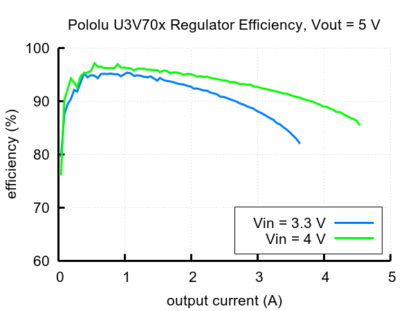
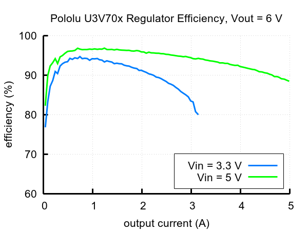
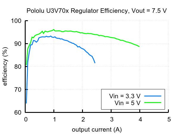
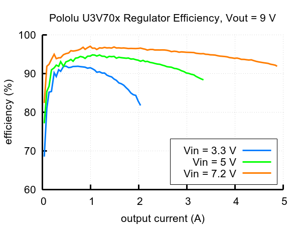
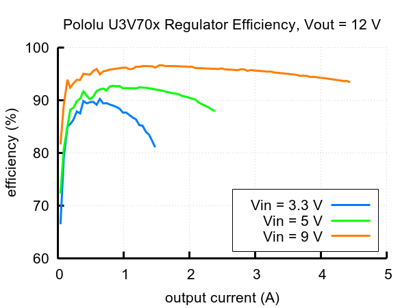
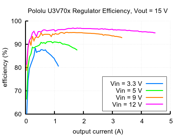
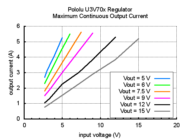
Typical efficiencies and maximum output currents
The efficiency of a voltage regulator, defined as (Power out)/(Power in), is an important measure of its performance, especially when battery life or heat are concerns. As shown in the graphs below, the U3V70x regulators have an efficiency of 80% to 95% for most combinations of input voltage, output voltage, and load.
 |
 |
 |
 |
 |
 |
The maximum achievable output current is approximately proportional to the ratio of the input voltage to the output voltage. Additionally, the maximum output current can depend on other factors, including the ambient temperature, air flow, and heat sinking. The graph below shows the typical maximum continuous output currents these regulators can deliver at room temperature with no forced airflow or heat sinking.
 |
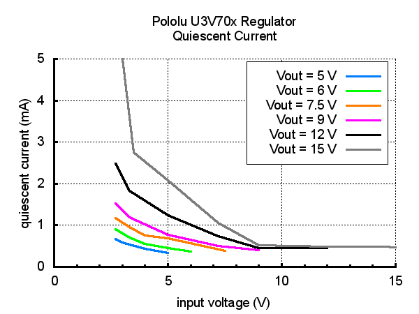 |
Typical maximum quiescent current of Step-Up Voltage Regulator U3V70x (regulator enabled, no load). |
|---|
During normal operation, this product can get hot enough to burn you. Take care when handling this product or other components connected to it.
LC Voltage Spikes
When connecting voltage to electronic circuits, the initial rush of current can cause damaging voltage spikes that are much higher than the input voltage. In Pololu's tests with this family of regulator connected with typical power leads (~30" test clips), Pololu found that input voltages above 17 V caused voltage spikes in excess of 20 V, which could damage the regulator. Lower input voltages caused smaller spikes that could still be problematic for boost regulators operating with the input voltage close to the set output voltage, since input voltages above the set output voltage will propagate to the output and could damage circuits being powered by the regulator. A large electrolytic capacitor (33 µF is a good starting point) can be added close to the regulator between VIN and GND to help suppress these spikes.
More information about LC spikes can be found in Pololu's application note, Understanding Destructive LC Voltage Spikes.
People often buy this product together with:
 | 12V Step-Up Voltage Regulator U3V70F12 |
 | 5V Step-Up Voltage Regulator U3V70F5 |
Dimensions
| Size: | 0.6" × 1.6" × 0.22"1 |
|---|---|
| Weight: | 3.9 g2 |
General specifications
| Minimum operating voltage: | 2.9 V |
|---|---|
| Maximum operating voltage: | 20 V3 |
| Maximum input current: | 10 A4 |
| Minimum output voltage: | 4.5 V5 |
| Maximum output voltage: | 20 V5 |
| Reverse voltage protection?: | Y |
| Output type: | adjustable 4.5-20V5 |
Identifying markings
| PCB dev codes: | reg21a |
|---|---|
| Other PCB markings: | 0J11050, blank white box |
Notes:
- 1
- Without included optional headers or terminal blocks. Height with terminal blocks installed is approximately 0.5".
- 2
- Without included optional headers or terminal blocks. Terminal blocks add 3.4 g.
- 3
- The operating voltage should not exceed the set output voltage, VOUT.
- 4
- Instantaneous. This is the rating for the switch, and regulator actively limits input current to this. Sustainable input current depends on input and output voltage and external conditions like ambient temperature and airflow.
- 5
- Output voltage is set by a built-in precision 12-turn potentiometer.
File downloads
-
Dimension diagram of the Step-Up Voltage Regulator U3V70x (150k pdf)
-
Drill guide for the Step-Up Voltage Regulator U3V70x (46k dxf)
This DXF drawing shows the locations of all of the board’s holes.
Exact shipping can be calculated on the view cart page (no login required).
Products that weigh more than 0.5 KG may cost more than what's shown (for example, test equipment, machines, >500mL liquids, etc).
We deliver Australia-wide with these options (depends on the final destination - you can get a quote on the view cart page):
- $3+ for Stamped Mail (typically 10+ business days, not tracked, only available on selected small items)
- $7+ for Standard Post (typically 6+ business days, tracked)
- $11+ for Express Post (typically 2+ business days, tracked)
- Pickup - Free! Only available to customers who live in the Newcastle region (must order online and only pickup after we email to notify you the order is ready). Orders placed after 2PM may not be ready until the following business day.
Non-metro addresses in WA, NT, SA & TAS can take 2+ days in addition to the above information.
Some batteries (such as LiPo) can't be shipped by Air. During checkout, Express Post and International Methods will not be an option if you have that type of battery in your shopping cart.
International Orders - the following rates are for New Zealand and will vary for other countries:
- $12+ for Pack and Track (3+ days, tracked)
- $16+ for Express International (2-5 days, tracked)
If you order lots of gear, the postage amount will increase based on the weight of your order.
Our physical address (here's a PDF which includes other key business details):
40 Aruma Place
Cardiff
NSW, 2285
Australia
Take a look at our customer service page if you have other questions such as "do we do purchase orders" (yes!) or "are prices GST inclusive" (yes they are!). We're here to help - get in touch with us to talk shop.
Have a product question? We're here to help!
 Gravity: I2C ADS1115 16-Bit ADC Module (Arduino & Raspberry Pi Compatible)SKU: DFR0553 Brand: DFRobotDFRobot I2C ADS1115 16-bit ADC module can accurately collect and convert analog ...
- Gravity: Analog Current to Voltage Converter(for 4~20mA Application)SKU: SEN0262 Brand: DFRobotThis current-to-voltage module can linearly convert 0~25mA current signals into ...
- A1102 Hall Effect SensorSKU: CE05296The A1101 Hall-effect switches include the following on a single silicon chip: v ...
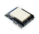
- ProtoShield + Mini Breadboard for ArduinoSKU: CE05308 Brand: Core ElectronicsCompatible with standard Arduino shield layout. Great for prototyping and quick ...


- Flexible Qwiic Cable - 100mmSKU: PRT-17259 Brand: SparkfunThis is a 100mm long 4-conductor cable with 1mm JST termination. It’s designed ...
- 3pc Heatsink Kit for Raspberry PiSKU: CE05645 Brand: Core ElectronicsA low-cost pack of heat sinks that are perfectly sized for the Raspberry Pi. Att ...
- M3 Mounting Kit (Standoffs)SKU: FIT0225 Brand: DFRobot
This M3 mounting kit provides you with different types of standoffs with scre ...
- AL Heat Sink (With adhesive tape) - 13*13*7mmSKU: FIT0191 Brand: DFRobotThis is a high-quality AL Heat Sink(With adhesive tape). There is a high-quality ...


Videos
View AllGuides

PiicoDev Magnetometer- Getting Started Guide

The Maker Revolution

How to Use DC Regulators/Converters

Powering Portable Projects: Batteries
Projects

Wireless QI Phone Charger Powered by Raspberry Pi

mmPi-Pico HAT

Solar Charging Station

Makers love reviews as much as you do, please follow this link to review the products you have purchased.
Product Comments