
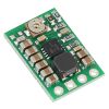
Pololu Adjustable Step-Up/Step-Down Voltage Regulator S7V8A
In stock, ships same business day if ordered before 2PM
Delivered by Tue, 4th of Aug
Quantity Discounts:
- 10+ $14.57 (exc GST)
- 25+ $14.12 (exc GST)
 |
The Pololu step-up/step-down voltage regulator S7V8A is a switching regulator (also called a switched-mode power supply (SMPS) or DC-to-DC converter) that uses a buck-boost topology. It takes an input voltage from 2.7 V to 11.8 V and increases or decreases the voltage to a user-adjustable output between 2.5 V and 8 V with a typical efficiency of over 90%. The input voltage can be higher than, lower than, or equal to the set output voltage, and the voltage is regulated to achieve the set output voltage.
This flexibility in input voltage is especially well-suited for battery-powered applications in which the battery voltage begins above the desired output voltage and drops below the target as the battery discharges. Without the typical restriction on the battery voltage staying above the required voltage throughout its life, new battery packs and form factors can be considered. For example:
- A 4-cell battery holder, which might have a 6 V output with fresh alkalines or a 4.0 V output with partially discharged NiMH cells, can be used with this regulator to power a 5 V circuit.
- A single lithium-polymer cell can run a 3.3 V device through its whole discharge cycle.
- A disposable 9 V battery powering a 5 V circuit can be discharged to under 3 V instead of cutting out at 6 V, as with typical linear or step-down regulators.
In typical applications, this regulator can deliver up to 1 A continuous when the input voltage is higher than the output voltage (stepping down). When the input voltage is lower than the output voltage (stepping up), the available current decreases as the difference between the voltages increases; please see the graphs at the bottom of this page for a more detailed characterization. The regulator has short-circuit protection, and thermal shutdown prevents damage from overheating; the board does not have reverse-voltage protection.
This regulator is also available with a fixed 3.3 V output or a fixed 5 V output.
Features
- Input voltage: 2.7 V to 11.8 V
- Output voltage adjustable from 2.5 V to 8 V
- Typical continuous output current: 500 mA to 1 A across most combinations of input and output voltages (Actual continuous output current depends on input and output voltages. See Typical Efficiency and Output Current section below for details.)
- Power-saving feature maintains high efficiency at low currents (quiescent current is less than 0.3 mA)
- Integrated over-temperature and short-circuit protection
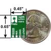
- Small size: 0.45" × 0.65" × 0.1" (11 × 17 × 3 mm)
- Complete schematic provided
 |
 |
Using the Regulator
During normal operation, this product can get hot enough to burn you. Take care when handling this product or other components connected to it.
Connections
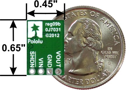
The step-up/step-down regulator has four connections: shutdown (SHDN), input voltage (VIN), ground (GND), and output voltage (VOUT).
The SHDN pin can be driven low (under 0.4 V) to power down the regulator and put it in a low-power state. The quiescent current in this sleep mode is dominated by the current in the 100k pull-up resistor from SHDN to VIN. With SHDN held low, this resistor will draw 10 µA per volt on VIN (for example, the sleep current with a 5 V input will be 50 µA). The SHDN pin can be driven high (above 1.2 V) to enable the board, or it can be connected to VIN or left disconnected if you want to leave the board permanently enabled.
The input voltage, VIN, should be between 2.7 V and 11.8 V. Lower inputs can shut down the voltage regulator; higher inputs can destroy the regulator, so you should ensure that noise on your input is not excessive, and you should be wary of destructive LC spikes (see below for more information).
The output voltage, VOUT, is determined by the trimmer potentiometer position. See the Setting the Output Voltage section below for details.
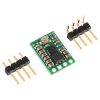
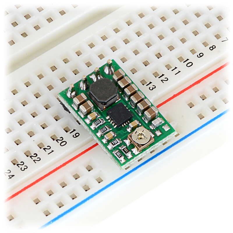
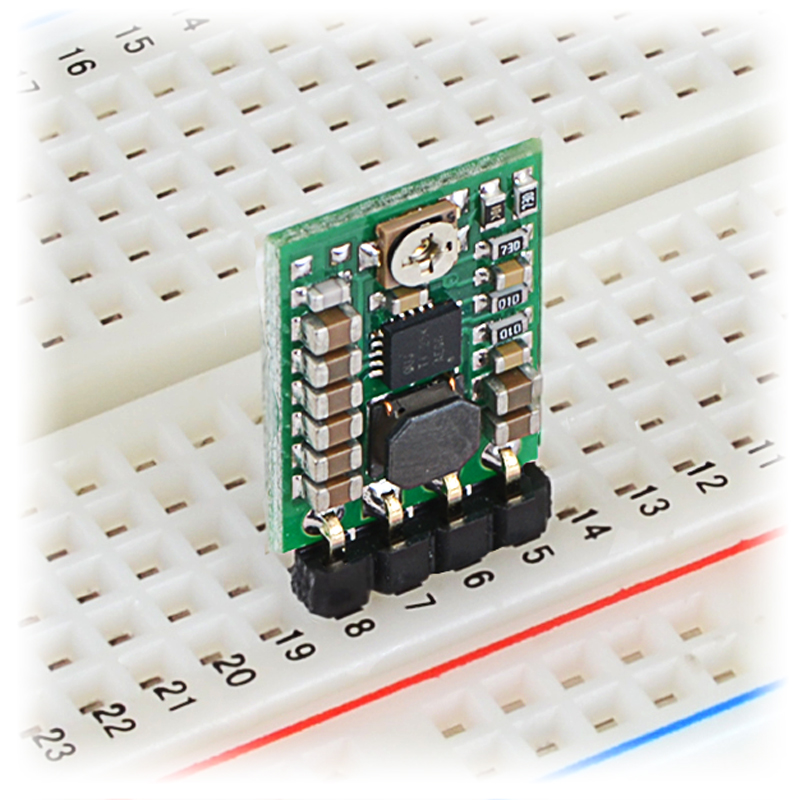
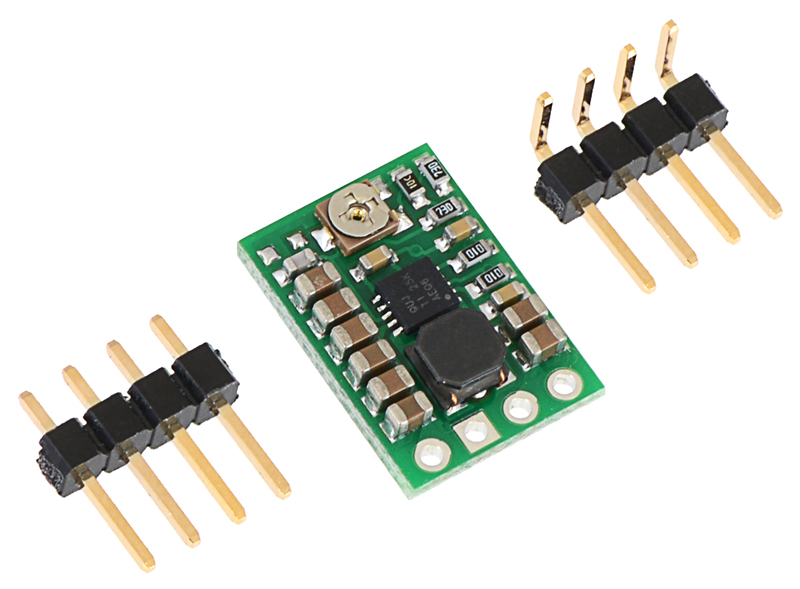
The four connections are labeled on the back side of the PCB, and they are arranged with a 0.1" spacing along the edge of the board for compatibility with standard solderless breadboards and perfboards and connectors that use a 0.1" grid. You can solder wires directly to the board or solder in either the 4×1 straight male header strip or the 4×1 right-angle male header strip that is included.
 |
Setting the Output Voltage
The output voltage can be measured using a multimeter. Turning the potentiometer clockwise increases the output voltage. The output voltage can be affected by a screwdriver touching the potentiometer, so the output measurement should be done with nothing touching the potentiometer.
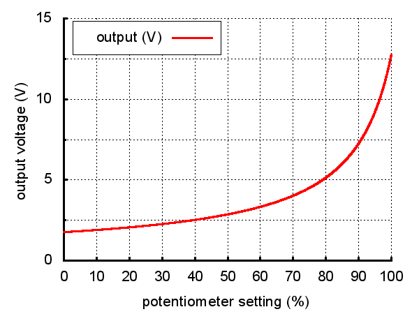 |
Output voltage settings for the Pololu step-up/step-down voltage regulator S7V8A. |
|---|
Please note that the output voltage can be set below 2.5 V at the low end of the potentiometer’s range and above 8 V at the high end. While this is not likely to damage the regulator, it might not work reliably or its output could become unstable when the output voltage is not within the recommended 2.5-8 V range. In addition, the potentiometer has no physical end stops, which means that the wiper can be turned 360 degrees and into an invalid region in which the output voltage is set to approximately 0.5 V.
The output voltage can be up to 3% higher than normal when there is little or no load on the regulator. The output voltage can also drop depending on the current draw, especially when the regulator is boosting a lower voltage to a higher one (stepping up), although it should remain within 5% of the set voltage.
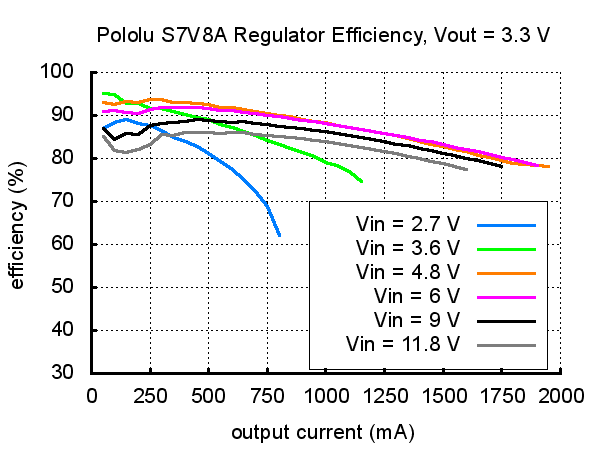
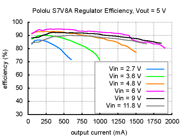
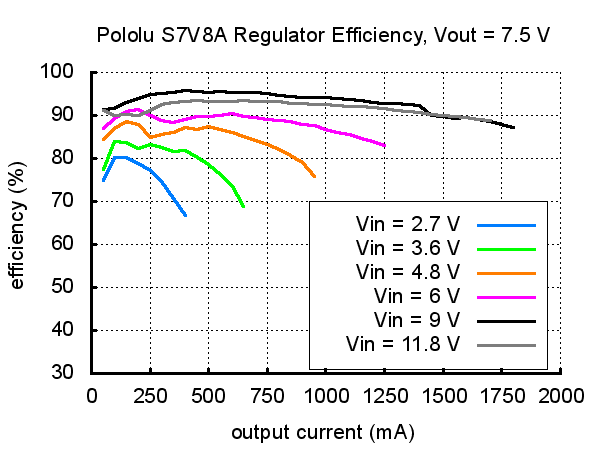
Typical Efficiency and Output Current
The efficiency of a voltage regulator, defined as (Power out)/(Power in), is an important measure of its performance, especially when battery life or heat are concerns. As shown in the graphs below, this switching regulator has an efficiency between 80% to 95% for most applications. A power-saving feature maintains these high efficiencies even when the regulator current is very low.
 |
 |
 |
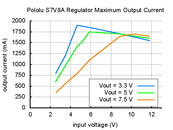
The maximum achievable output current of the board varies with the input voltage but also depends on other factors, including the ambient temperature, air flow, and heat sinking. The graph below shows output currents at which this voltage regulator’s over-temperature protection typically kicks in after a few seconds. These currents represent the limit of the regulator’s capability and cannot be sustained for long periods, so the continuous currents that the regulator can provide are typically several hundred milliamps lower, and Pololu recommend trying to draw no more than about 1 A from this regulator throughout its input voltage range.
 |
LC Voltage Spikes
When connecting voltage to electronic circuits, the initial rush of current can cause voltage spikes that are much higher than the input voltage. If these spikes exceed the regulator’s maximum voltage, the regulator can be destroyed. If you are connecting more than about 9 V, using power leads more than a few inches long, or using a power supply with high inductance, Pololu recommend soldering a 33 µF or larger electrolytic capacitor close to the regulator between VIN and GND. The capacitor should be rated for at least 16 V.
More information about LC spikes can be found in Pololu's application note, Understanding Destructive LC Voltage Spikes.
People often buy this product together with:
 | Pololu 5V Step-Up/Step-Down Voltage Regulator S7V7F5 |
 | Pololu 3.3V Step-Up/Step-Down Voltage Regulator S7V8F3 |
| Pololu 5V Step-Up/Step-Down Voltage Regulator S7V8F5 |
Dimensions
| Size: | 0.45" × 0.65" × 0.1"1 |
|---|---|
| Weight: | 0.6 g1 |
General specifications
| Minimum operating voltage: | 2.7 V |
|---|---|
| Maximum operating voltage: | 11.8 V |
| Maximum output current: | 1 A2 |
| Minimum output voltage: | 2.5 V |
| Maximum output voltage: | 8 V |
| Reverse voltage protection?: | N |
| Maximum quiescent current: | 0.3 mA3 |
Identifying markings
| PCB dev codes: | reg09b |
|---|---|
| Other PCB markings: | 0J7031 |
Notes:
- 1
- Without included optional headers.
- 2
- When stepping down; current available when stepping up depends on input and output voltages (over 500 mA in most configurations).
- 3
- While enabled (SHDN = HIGH) with no load. Actual quiescent current depends on input and output voltages.
File downloads
-
Pololu Step-Up/Step-Down Voltage Regulator S7V8x schematic diagram (192k pdf)
Printable schematic diagram for the S7V8x family of Pololu step-up/step-down voltage regulators: S7V8A, S7V8F3, and S7V8F5.
-
Dimension diagram of the S7V8x Step-Up/Step-Down Voltage Regulator (211k pdf)
-
3D model of the Pololu Adjustable Step-Up/Step-Down Voltage Regulator S7V8A (4MB step)
-
Pololu Step-Up/Step-Down Voltage Regulator S7V8x drill guide (22k dxf)
This DXF drawing shows the locations of all of the board’s holes.
Recommended links
Exact shipping can be calculated on the view cart page (no login required).
Products that weigh more than 0.5 KG may cost more than what's shown (for example, test equipment, machines, >500mL liquids, etc).
We deliver Australia-wide with these options (depends on the final destination - you can get a quote on the view cart page):
- $3+ for Stamped Mail (typically 10+ business days, not tracked, only available on selected small items)
- $7+ for Standard Post (typically 6+ business days, tracked)
- $11+ for Express Post (typically 2+ business days, tracked)
- Pickup - Free! Only available to customers who live in the Newcastle region (must order online and only pickup after we email to notify you the order is ready). Orders placed after 2PM may not be ready until the following business day.
Non-metro addresses in WA, NT, SA & TAS can take 2+ days in addition to the above information.
Some batteries (such as LiPo) can't be shipped by Air. During checkout, Express Post and International Methods will not be an option if you have that type of battery in your shopping cart.
International Orders - the following rates are for New Zealand and will vary for other countries:
- $12+ for Pack and Track (3+ days, tracked)
- $16+ for Express International (2-5 days, tracked)
If you order lots of gear, the postage amount will increase based on the weight of your order.
Our physical address (here's a PDF which includes other key business details):
40 Aruma Place
Cardiff
NSW, 2285
Australia
Take a look at our customer service page if you have other questions such as "do we do purchase orders" (yes!) or "are prices GST inclusive" (yes they are!). We're here to help - get in touch with us to talk shop.
Have a product question? We're here to help!
 Waveshare 4G HAT for Raspberry Pi (LTE Cat-4/4G/3G/2G/GNSS)SKU: WS-17372 Brand: WaveshareEnable LTE Cat-4 4G/3G/2G communication and GNSS Positioning for your Raspberry ...
- SIM7080G NB-IoT / Cat-M(eMTC) / GNSS Module for Raspberry Pi Pico, Global Band SupportSKU: WS-20036 Brand: WaveshareSIM7080G NB-IoT / Cat-M(EMTC) / GNSS Module For Raspberry Pi Pico, Global Band S ...
- Lipo Rider Plus (Charger/Booster) - 5V/2.4A USB Type CSKU: SS106990290 Brand: Seeed StudioWelcome to the era of fast charging! 5V/2A Lipo Rider Plus will greatly increase ...
- Adjustable Switching Power Supply Module IN 4V-35V OUT 1.5V-30V LM2596S Step-Down ConverterSKU: CE05572 Brand: Core ElectronicsA versatile power supply DC-DC converter module that offers a wide range for bot ...


- Adafruit Universal USB / DC / Solar Lithium Ion/Polymer charger - bq24074SKU: ADA4755 Brand: AdafruitThis charger is the only one you need to keep all your Lithium Polymer (LiPoly) ...
- Waterproof Cable Gland PG-7 Size (Black)SKU: FIT0727 Brand: DFRobotWaterproof is always a critical point for outdoor projects, and when you need to ...
- Plastic Project Box Enclosure Waterproof Clear Cover - 168 x 120 x 55 mmSKU: FIT0723 Brand: DFRobotProtect your electronic projects from rain and water splash using this waterproo ...


Videos
View AllGuides

PiicoDev Magnetometer- Getting Started Guide

The Maker Revolution

How to Use DC Regulators/Converters

Powering Portable Projects: Batteries
Projects

Wireless QI Phone Charger Powered by Raspberry Pi

mmPi-Pico HAT

Solar Charging Station

Makers love reviews as much as you do, please follow this link to review the products you have purchased.
Product Comments