
Pololu 24V Step-Up Voltage Regulator U3V50F24
In stock, ships same business day if ordered before 2PM
Fastest delivery: Tomorrow*
Disclaimer:
For next-day delivery, the shipping address must
be in the AusPost next-day network, eParcel Express must be selected, and the order must be placed
before 2PM AEST Mon-Thurs excluding NSW Public Holidays. Orders may be delayed due to AusPost
pickup timings and order verifications. eParcel Express is typically a 1-day service within the
AusPost next-day network, though it is sometimes 2+ days.
Quantity Discounts:
- 6+ $45.69 (exc GST)
- 12+ $44.26 (exc GST)
Note: Pololu recommends Pololu's newer U3V70x family of boost regulators over these older U3V50x regulators for applications that require 20 V or less. The U3V70x regulators are smaller and can deliver more current, and the adjustable version features a precision 12-turn potentiometer, which makes it easier to set the output voltage to a particular value.
 |
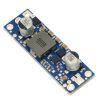
These boost (step-up) voltage regulators generate higher output voltages from input voltages as low as 2.9 V. They are switching regulators (also called switched-mode power supplies (SMPS) or DC-to-DC converters) and have a typical efficiency between 80% to 95%. The available output current is a function of the input voltage, output voltage, and efficiency (see the Typical Efficiency and Output Current section below), but the input current can typically be as high as 5 A. This regulator is available with a fixed 5 V, 6 V, 9 V, 12 V, or 24 V output.
The U3V50x regulator family also includes two adjustable-output versions: the U3V50ALV offers an output range of 4 V to 12 V and the U3V50AHV offers an output range of 9 V to 30 V. The different versions of the board all look very similar, so the bottom silkscreen includes a blank space where you can add your own distinguishing marks or labels.
The no-load quiescent current will typically be between 1 mA and 5 mA for most combinations of input and output voltages, though the combination of a very high output voltage and a very low input voltage (e.g. when boosting from 3 V in to 30 V out) can result in quiescent currents on the order of a few dozen milliamps. The ENABLE pin can be used to put the board in a low-power state that reduces the quiescent current to approximately 20 µA per volt on VIN.
This regulator has built-in reverse-voltage protection, over-current protection, thermal shutdown (which typically activates at 165°C), and an under-voltage lockout that causes the regulator to turn off when the input voltage is below 2.5 V (typical).
Features
- Input voltage: 2.9 V to VOUT
- Fixed 5 V, 6 V, 9 V, 12 V or 24 V output with 4% accuracy
- 5 A switch allows for input currents up to 5 A
- Integrated reverse-voltage protection, over-current protection, over-temperature shutoff, and under-voltage lockout
- Typical efficiency of 80% to 95%, depending on input voltage, output voltage, and load
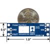
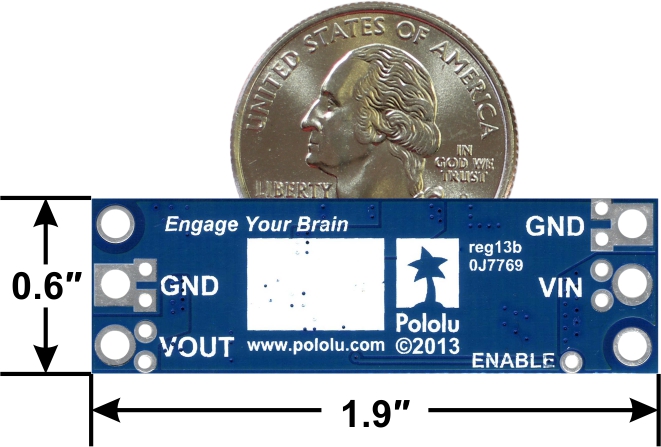
- Compact size: 1.9" × 0.6" × 0.41" (48 × 15 × 10.5 mm)
- Two mounting holes for #2 or M2 screws
- Smaller holes for 0.1" header pins and larger holes for terminal blocks offer several options for connecting to the board
Using the regulator
Connections
This boost regulator has four connections: input voltage (VIN), ground (GND), and output voltage (VOUT), and ENABLE.
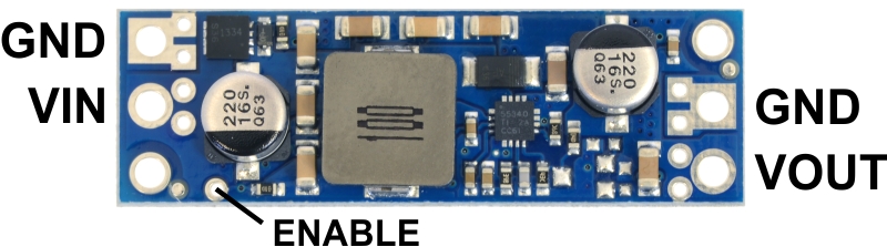 |
The input voltage, VIN, must be at least 2.9 V and should not exceed the output voltage, VOUT. (If VIN is higher than VOUT, the higher input voltage will show up on the output, which is potentially dangerous for your connected load and could also damage the regulator.)
The regulator is enabled by default: a 100 kO pull-up resistor on the board connects the ENABLE pin to reverse-protected VIN. The ENABLE pin can be driven low (under 0.7 V) to put the board into a low-power state. The quiescent current draw in this sleep mode is dominated by the current in the pull-up resistor from ENABLE to VIN and by the reverse-voltage protection circuit, which will draw between 10 µA and 20 µA per volt on VIN when ENABLE is held low. If you do not need this feature, you should leave the ENABLE pin disconnected. Note that like most boost regulators, the input power will pass through to the output when the board is disabled, so the ENABLE pin cannot be used to turn off power to the load.
|
|
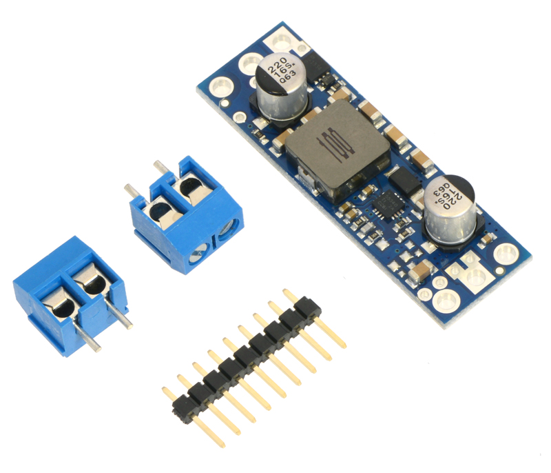
The connections are labeled on the back side of the PCB, and the board offers several options for making electrical connections. The eight smaller through-holes on the ends of the board are arranged with a 0.1" spacing for compatibility with solderless breadboards, connectors, and other prototyping arrangements that use a 0.1" grid; you can solder pieces of the included 9×1 straight male header strip into these smaller holes. Alternatively, you can solder the included 2-pin 5mm-pitch terminal blocks to the two pairs of larger holes on the ends of the board. For the most compact installation, you can solder wires directly to the board.
Note that this regulator has a thick PCB (0.093"), so terminal block and header pins will not protrude as far through the holes as they would with typical 0.062"-thick PCBs.
 |
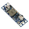
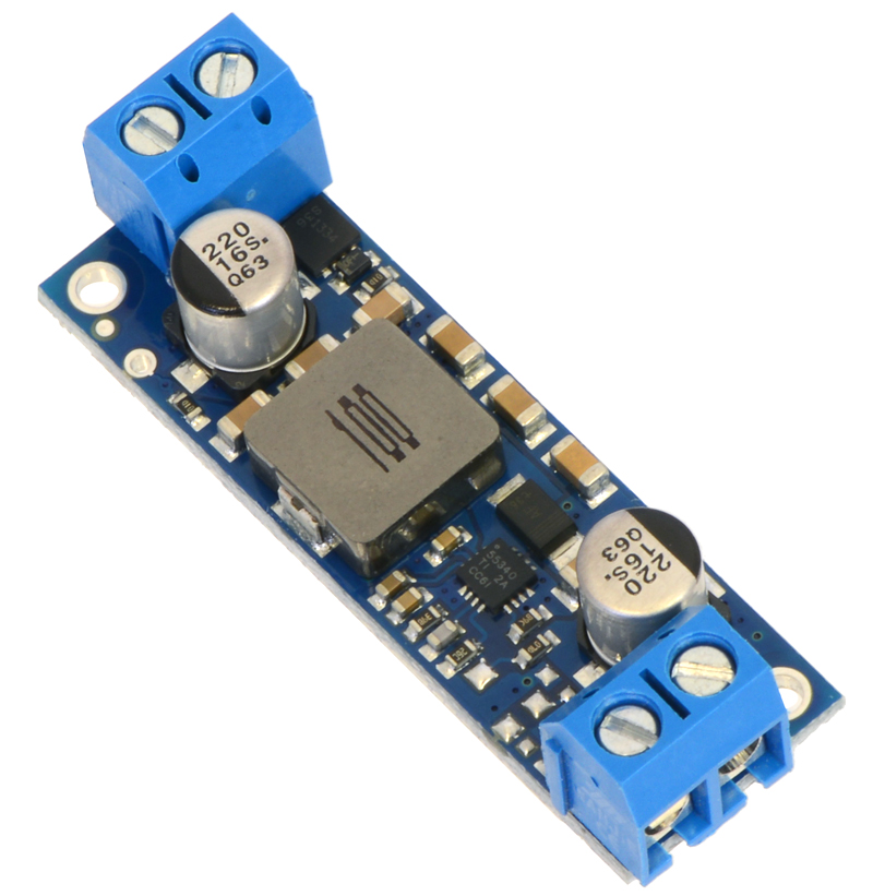
Pololu step-up voltage regulator U3V50x with included terminal blocks installed, side view. |
|---|
The board has two mounting holes intended for #2 or M2 screws. The mounting holes are at opposite corners of the board, separated by 1.7" horizontally and 0.4" vertically.
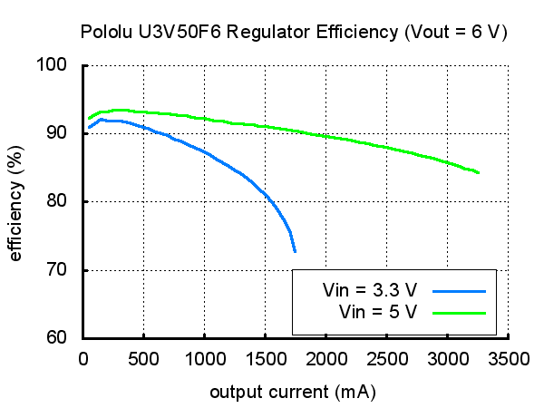
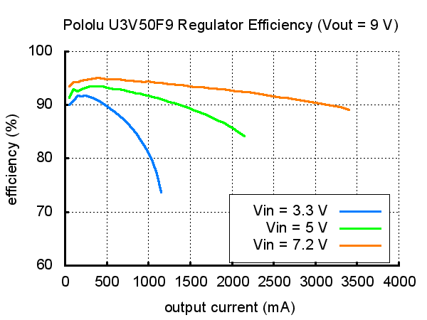
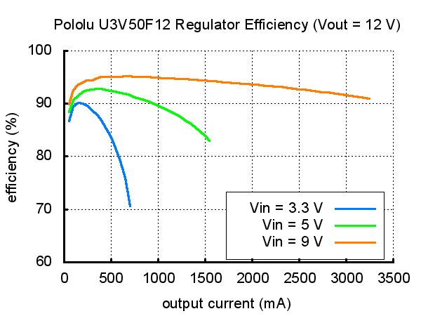
Typical efficiency and output current
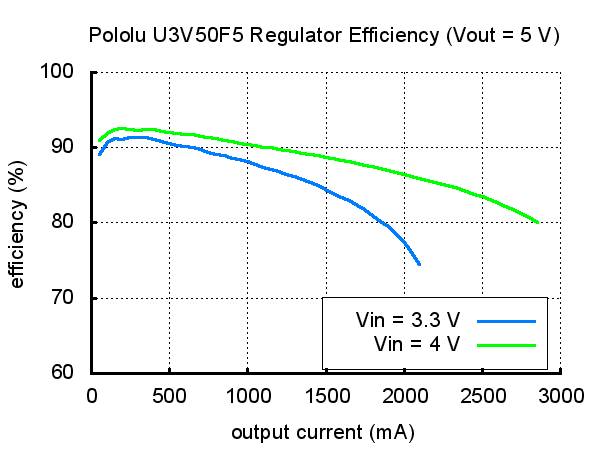
The efficiency of a voltage regulator, defined as (Power out)/(Power in), is an important measure of its performance, especially when battery life or heat are concerns. As shown in the graphs below, these switching regulators have an efficiency of 80% to 95% for most combinations of input voltage, output voltage, and load.
 |
 |
 |
 |
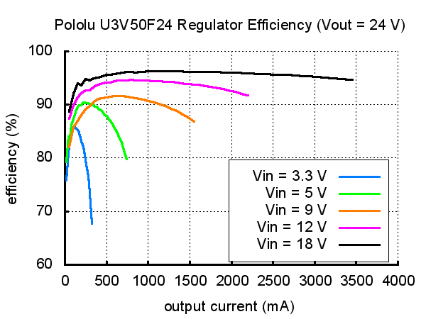 |
The maximum achievable output current is approximately proportional to the ratio of the input voltage to the output voltage. If the input current exceeds the 5 A switch current limit, the output voltage will begin to drop. Additionally, the maximum output current can depend on other factors, including the ambient temperature, air flow, and heat sinking.
During normal operation, this product can get hot enough to burn you. Take care when handling this product or other components connected to it.
People often buy this product together with:
 | Pololu 5V, 5A Step-Down Voltage Regulator D24V50F5 |
Dimensions
| Size: | 0.6" × 1.9" × 0.41"1 |
|---|---|
| Weight: | 7.5 g2 |
General specifications
| Minimum operating voltage: | 2.9 V |
|---|---|
| Maximum operating voltage: | 24 V |
| Maximum input current: | 5 A |
| Output voltage: | 24 V |
| Reverse voltage protection?: | Y |
| Maximum quiescent current: | 30 mA3 |
Identifying markings
| PCB dev codes: | reg13b |
|---|---|
| Other PCB markings: | 0J7769, blank white box |
Notes:
- 1
- Without included optional headers or terminal blocks. Height with terminal blocks installed is approximately 0.5".
- 2
- Without included optional headers or terminal blocks. Terminal blocks add 3.4 g.
- 3
- Typical worst case (i.e. with VIN at 3 V). Quiescent current depends on the input and output voltages and is much lower for most of the input voltage range. The ENABLE pin can be used to reduce the quiescent current to well under 1 mA.
File downloads
Dimension diagram of the U3V50x Pololu Step-Up Voltage Regulator (154k pdf)
Pololu Step-Up Voltage Regulator U3V50x drill guide (46k dxf)
This DXF drawing shows the locations of all of the board’s holes.
Exact shipping can be calculated on the view cart page (no login required).
Products that weigh more than 0.5 KG may cost more than what's shown (for example, test equipment, machines, >500mL liquids, etc).
We deliver Australia-wide with these options (depends on the final destination - you can get a quote on the view cart page):
- $3+ for Stamped Mail (typically 10+ business days, not tracked, only available on selected small items)
- $7+ for Standard Post (typically 6+ business days, tracked)
- $11+ for Express Post (typically 2+ business days, tracked)
- Pickup - Free! Only available to customers who live in the Newcastle region (must order online and only pickup after we email to notify you the order is ready). Orders placed after 2PM may not be ready until the following business day.
Non-metro addresses in WA, NT, SA & TAS can take 2+ days in addition to the above information.
Some batteries (such as LiPo) can't be shipped by Air. During checkout, Express Post and International Methods will not be an option if you have that type of battery in your shopping cart.
International Orders - the following rates are for New Zealand and will vary for other countries:
- $12+ for Pack and Track (3+ days, tracked)
- $16+ for Express International (2-5 days, tracked)
If you order lots of gear, the postage amount will increase based on the weight of your order.
Our physical address (here's a PDF which includes other key business details):
40 Aruma Place
Cardiff
NSW, 2285
Australia
Take a look at our customer service page if you have other questions such as "do we do purchase orders" (yes!) or "are prices GST inclusive" (yes they are!). We're here to help - get in touch with us to talk shop.
Have a product question? We're here to help!
 DC-DC boost converterSKU: DFR0123 Brand: DFRobotThis is a boost converter. Supply voltage as low as 5v, it boosts to as high as ...
- DC-DC Adjustable Step-down Module 5A 75WSKU: CE07271 Brand: Core ElectronicsDC-DC Adjustable Step Down Module 5A 75W XL4015
- DC-DC Multi-output Buck Converter (3.3V/5V/9V/12V)SKU: DFR1015 Brand: DFRobotThis DC-DC Step Down Voltage Converter steps down voltage from 7.5V~30V to 3.3V/ ...
- Waveshare RP2040-ETH Mini Development BoardSKU: WS-24082 Brand: WaveshareWaveshare RP2040-ETH Mini Development Board, RP2040 Ethernet Port Module, Raspbe ...


- Arduino Nano V3.2SKU: A000005 Brand: ArduinoThe Arduino Nano is a smaller form factor version of the Arduino UNO, one that i ...
- Mini B USB cableSKU: FIT0057 Brand: DFRobotUSB 2.0 type A to mini USB 5-pin. This is a new, smaller connector for USB devic ...
- Large Enclosed Piezo Element w/WiresSKU: ADA1739 Brand: AdafruitThis large (30mm diameter) piezo element is nicely enclosed with mounting holes ...
- Pololu Adjustable 9-30V Step-Up Voltage Regulator U3V50AHVSKU: POLOLU-2571 Brand: PololuThis powerful boost regulator efficiently boosts input voltages as low as 2.9 V ...


Videos
View AllGuides

PiicoDev Magnetometer- Getting Started Guide

The Maker Revolution

How to Use DC Regulators/Converters

Powering Portable Projects: Batteries
Projects

Wireless QI Phone Charger Powered by Raspberry Pi

mmPi-Pico HAT

Solar Charging Station

Makers love reviews as much as you do, please follow this link to review the products you have purchased.
Product Comments