This guide will teach you exactly how to use a Raspberry Pi Single Board Computer to independently control 4 relays. A Relay is an electrically operated switch. This is all possible thanks to the PiRelay V2 HAT from SB Components. These relays are strong enough to switch loads of up to 30Volts DC at 10 Amps!
Think of relays as On/Off switches that are controlled by a computer. In this big world, there is a whole bunch of high current, high voltage devices. Now a Raspberry Pi Single Board computer operates at 5 Volts. If 30 Volts were driven directly through it, our computer would break. Does that mean we cannot control high current/voltage devices with our 5 Volt computer? Absolutely not, we can use Relays. We can send our Relay a signal at 5 Volts from our Raspberry Pi. That signal will then open/close electrical flow to our high voltage system.
Relays are a great method of computer control whilst insulating delicate electronics from high currents and voltages. Relays and Home Automation go hand in hand. You will find jellybean relay components for all electrical situations and specifications. The PiRelay V2 HAT is a completely solderless solution to driving 30 Volts DC at 10 Amps from a Raspberry Pi Single Board Computer. With our system here I'll even show you how to control the Relays through your voice and utilise a Touch Screen Display control. The contents of this guide can be seen below.
- What You Need
- Hardware Assembly
- Software to Set Up
- Code to Activate the Relays
- Voice Activated Relays
- GPIO Touch Screen Relay Activation
- Where to Now
- Download Python Scripts
This HAT packs a whopping 4 Relays and can be controlled directly by a Raspberry Pi Board through I2C communication. This means you can stack these Hats for even more Relay control! These HATs are designed to keep your Raspberry Pi Safe. Also, keep in mind there is a 2 Relay HAT Version that fits cleanly onto a Raspberry Pi Zero and Raspberry Pi Zero 2. If 4 Relays on a single stackable HAT are not enough for you then check out the 8 Relays Card V2 for Raspberry Pi. Every space millimeter of space is taken up by Electro-Mechanical Relay Modules that each can switch 24Volts DC at 8 Amps. If you are interested in controlling even higher currents, voltages or AC electricity give the SparkFun Qwiic Quad Solid State Relay Kit a look. That relay kit is capable of shuffling around 40 Amps at 28-380 Volts AC!
All relays on the PiRelay V2 HAT are electromechanical relays. You can identify them as the four black boxes on the top of the board. These are electromechanical as inside they have physically moving contacts on the output circuit. Below is an image demonstrating the internals of one of these Black Relay Boxes. These moving contacts are operated by applying an electrical signal through an electromagnetic coil. This coil creates a magnetic field that pushes/pulls the magnetic contact open and closed. In the below image the moving contact path is indicated by a green arrow.

If you happen to be holding a Raspberry Pi board and are not quite sure what it is? Then check out this guide Raspberry Pi Generations to identify it. As always if you have any questions, queries, thoughts, or comments please let me know!
What You Need
Below is everything you need to set up your Raspberry Pi to work with the PiRelay V2 HAT from SB Components.
- A Raspberry Pi Palm-Sized Computer (in my case I have used a Raspberry Pi 4 Model B 2GB but this can be done perfectly with an earlier lower-spec Pi like the Raspberry Pi 3)
- PiRelay V2 HAT
- Micro-SD card flashed with Raspberry Pi OS
- Micro-HDMI to HDMI Cord to connect the system to a Monitor
- Power Supply
- Mouse and Keyboard
- Optional USB Microphone (Only for Voice-Activated Relay Control)
- Optional GPIO Connected Screen (Only for Touch-Screen Relay Control)
Hardware Build
To start below is an image that shows everything that you get when you have a new PiRelay V2 HAT in hand. Note the yellow jumpers on the top right of the board. If you pull any of these off the corresponding Relay will no longer function. This can be useful for situations where you are concerned about the current draw and do not need four relays in your system.

Let us now begin assembly. Attach the Relay HAT to the top of the Raspberry Pi by lining up the headers of the HAT with the GPIO pins of the Raspberry Pi. See this happening in the image below. Take care that all the pins are correctly lined up and that the HAT is fully seated.

With that complete attach the desired relay outputs to on the HAT. Let me just state here. If you have no experience working with Mains Power do not hook up Mains Power to a Relay. Particularly in Australia, our 240 Volts at 50Hz AC is life-threatening and it is proper necessary to have credentials, experience, knowledge, and certificates. Thus for today, I’ll attach a to our system devices that are all driven safely via Battery power.
Take careful note to connect your devices to the Raspberry Pi System correctly. The PCB has four groups of three screw-down terminal connectors. Each group of screw-down terminals has clearly labeled next to them the associated Relay it corresponds to (Relay 1, Relay 2, etc). Each group of screw-down terminals has in front of each terminal node the text | NO |, | COM |, and | NC |. | COM | stands for Common connection, this connects directly to the mechanically moving part of the relay. Under normal situations, we would connect the Ground (Black) Wire of our system to this.
The | NO | stands for Normally Open. The | NC | stands for Normally Closed. Normally Open and Normally Closed are terms to define the states of switches, sensors, or relay contacts are under when the magnetic coil is not excited. If you want to power to go to the externally switched system whenever the Relay is activated attach Positive (Red) Wire to Normally Open. If you want to stop power going to the externally switched system whenever the Relay is activated attach Positive (Red) Wire to Normally Closed. Be aware that certain hardware (like Solenoids) will get hot/overheat if in a powered/activated state for too long, that is why we have normally open or normally closed as options. Side note, I have created a guide on Powering Solenoids with a Raspberry Pi Utilising a Relay, come take a look if you are interested.

Below left image shows a single external system connected to the | Relay 1 | Screw-down Terminals. In scripts, we will refer to and identify the Relays by the numbers written on the PCB board. The external system is connected to the | NO | and | COM | screw-down terminals. Note that this external system has its own power (the 9V battery). Our Raspberry Pi system will simply enable us to close the circuit. The Raspberry Pi Relay System's only difference from a Switch is that the On/Off status of connected devices is toggled electronically (instead of a human being manually turning it On/Off). The image below tries to relay that sentiment with a comically large switch.

With that complete, insert a micro-SD card flashed with Raspberry Pi OS and hook it up as a desktop computer. Add a mouse, keyboard, and HDMI to a monitor. Then power up the Raspberry Pi System by plugging in a USB-C connector. I will also connect that Optional USB microphone. See all of these parts, as well as the mouse and keyboard, attached together below.

With that complete, I will do an optional extra step and add a GPIO-connected touch screen to the top of our Raspberry Pi Stack. The exact screen I will use here is the Waveshare 3.5 Inch LCD 480x320. This you can see installed on top of a Raspberry Pi Single Board computer in the image below. You can use any similar form factor screen. I would also recommend using a stackable header so that none of the electronic layers are touching, without it the screen does sag onto the relays slightly. We will then be able to turn our devices on and off via a UI displayed on the touch screen.

Software Set Up
Some packages will need to be installed on your fresh version of Raspberry Pi OS. This will allow correct communication between the Relay HAT and your Raspberry Pi. With the power into the system and the (new) first boot-up wizard complete, you will be welcomed by the Raspberry Pi Desktop.
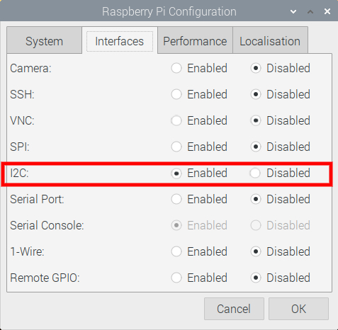
Now the PiRelay V2 HAT requires I2C communication to work. By default on Raspberry Pi OS, this communication method is turned off. So the first step is to turn that on. To do this open up the Raspberry Pi Configuration menu (found using the top left menu and scrolling over Preferences) and then enable the I2C Connection found under the Interfaces tab. When here double check that | 1-Wire | is disabled. If enabled Relay 4 will not operate correctly. Also, make sure that Serial Port is enabled. See all this in the image below. After enabling, reset the Raspberry Pi to lock in the change.
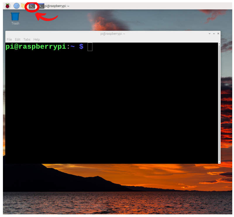
Now with your system rebooted and connected to the internet, open a new terminal window by pressing the black button on the top left of the screen. This will open up a terminal window. See the image below of this happening and a big red arrow pointing towards the terminal button that was pressed.
This terminal window will enable us to download from the internet the exact packages we require. So now type and enter the following lines into the terminal to get all the packages that you will need. If prompted, type and enter | Y | to continue/confirm installations. See further below an image of one of these commands being downloaded and requesting this confirmation.
sudo apt-get update
git clone https://github.com/sbcshop/PiRelay-V2
sudo apt-get install flac
sudo apt-get install python3-pyaudio
sudo pip3 install SpeechRecognition

Once completed we have fully set up our Raspberry Pi Single Board Computer to work with the PiRelay V2 HAT.
Code to Activate the Relays
There are a lot of ways you can get the Raspberry Pi to activate the connected Relays. I will do the most intuitive and fastest by connecting this Raspberry Pi up to a monitor with a mouse and keyboard and directly writing Python scripts to control them. Check out this guide if you need help doing this. With those peripheries connected, plug in the USB C Power supply to the Raspberry Pi. Then complete the new first start wizard and with that done you will be welcomed by the familiar Raspberry Pi desktop.
The first Python script we are interested in is called | test.py | and can be found in the folder location | /home/pi/PiRelay-V2 |. As you have completed the above terminal commands you will have these examples scripts in the exact same location too! See an image below of the file manager showing the file location.

From here open up a Python interface like Thonny IDE. Thonny IDE is just a Python Interpreter software and you can use whichever is your preference. We will code using the Python Programming Language. Click on the Application Menu (this is the Raspberry Pi Symbol on the top left of the screen) and hover over the Programming Tab to find Thonny IDE. Then open up the script using the | Load | button or copy and paste the following script into the coding area. Save the script in the same directory location | /home/pi/PiRelay-V2 | and run it by pressing the big green Run button. The only difference with the below script is slightly longer delays between switching Relays and more comments to aid understanding. You can also download all scripts talked about in this guide in the download section found at the bottom of the page.
#Import all necessary packages
import PiRelay
import time

#Create Variable names to quickly identify and target the relay you want to activate
r1 = PiRelay.Relay("RELAY1")
r2 = PiRelay.Relay("RELAY2")
r3 = PiRelay.Relay("RELAY3")
r4 = PiRelay.Relay("RELAY4")

#Below demonstrates and is the command to toggle on relay 1 as labeled on the PiRelay V2
r1.on()

#Below is a small time delay. Relay 1 will remain energised during this.
time.sleep(1)

#Below demonstrates and is the command to toggle off relay 1 as labeled on the PiRelay V2
r1.off()

#Below is a small time delay. Relay 1 will remain de-energised during this.
time.sleep(1)

#The rest of this script is systematically turning on and off relay 2, relay 3 and relay 4 one by one, with a 1 second pause between each.
r2.on()
time.sleep(1)
r2.off()
time.sleep(1)
r3.on()
time.sleep(1)
r3.off()
time.sleep(1)
r4.on()
time.sleep(1)
r4.off()
time.sleep(1)

#Note that all relays upon the end of the Python Script are de-energised. A relay left turned on for too long will get hot. For a long relay lifespan energising the relay for a short time is best.
With that done you can now have the tool to electrically switch through any of the relays, at any time you desire. You could also add Threshold Values. For example, you could have a light sensor that when it registers that everything is dark it’ll turn on all the relay attached lights in your house. In that case, you will want to utilise an endless loop (| for True: | or | while True: |) to constantly check if that Threshold Value has been met. Then when it does use an | If | statement combined with the | r1.on() | command. Check out my Python Workshop if you need any Tips on doing this and to help take your Python Programming skills to the next level. See this | test.py | script opened up in Thonny IDE and running in the Image below. To the right of the image, you can see the effect it has on our Brushed DC Motor System that is attached to Relay 1.

Voice Activated Relay Control
This works so much better than I first thought so I have to show it off. With this added to your system, you will be able to control your Relay-connected systems through words that you say. Any word or phrase can be your keyword to get your system started. You will need to be connected to the WIFI for the system to work.
There is a default example script that you can locate in the location | /home/pi/PiRelay-V2/PiRelay_Voice_Control.py |. To run this script you will need to adjust the line | if mic == 'Yeti Stereo Microphone: USB Audio (hw:0,0)': | so that the script can focus on your specific microphone. With my connected USB microphone, the line was adjusted to | if mic == 'USB PnP Sound Device: Audio (hw:3,0)'': |. If you are using a different microphone you can run the two-line | MicList.py | script seen open in Thonny IDE in the image below to identify Microphones in your system. You can download the below script, along with any Python scripts in this guide, in the download section at the bottom of this page.

Once you have identified your microphone and altered the | PiRelay_Voice_Control.py | to accommodate for your particular microphone it should look very similar to my script below. Feel free to copy and paste the below into a new Thonny IDE instance if you are running the exact same hardware as outlined in this guide. You can of course just download it directly from the bottom of the article.
import speech_recognition as sr
import time, datetime
import PiRelay
import re

relay1 = PiRelay.Relay("RELAY1")
relay2 = PiRelay.Relay("RELAY2")
relay3 = PiRelay.Relay("RELAY3")
relay4 = PiRelay.Relay("RELAY4")

sample_rate = 48000
chunk_size = 2048

r = sr.Recognizer()

device_id = 0
mic_list = sr.Microphone.list_microphone_names()
for mic in mic_list:
    if mic == 'USB PnP Sound Device: Audio (hw:3,0)':
        device_id = mic_list.index(mic)

while True:
    with sr.Microphone(device_index = device_id, sample_rate = sample_rate,
                        chunk_size = chunk_size) as source:
        r.adjust_for_ambient_noise(source)
        print("Say Something")
        audio = r.listen(source)

    try:
        text = r.recognize_google(audio)
        text = text.lower()
        print("you said: " + text)
        if re.search("rel", text):
            if re.search('on', text):
                if re.search("1", text):
                    print("Turn On Relay 1")
                    relay1.on()
                elif re.search("2", text):
                    print("Turn On Relay 2")
                    relay2.on()
                elif re.search("3", text):
                    print("Turn On Relay 3")
                    relay3.on()
                elif re.search("4", text):
                    print("Turn On Relay 4")
                    relay4.on()
                elif re.search("all", text):
                    print("Turn On All Relay")
                    relay1.on()
                    relay2.on()
                    relay3.on()
                    relay4.on()

            if re.search('off', text):
                if re.search("1", text):
                    print("Turn Off Relay 1")
                    relay1.off()
                elif re.search("2", text):
                    print("Turn Off Relay 2")
                    relay2.off()
                elif re.search("3", text):
                    print("Turn Off Relay 3")
                    relay3.off()
                elif re.search("4", text):
                    print("Turn Off Relay 4")
                    relay4.off()
                elif re.search("all", text):
                    print("Turn Off All Relays")
                    relay1.off()
                    relay2.off()
                    relay3.off()
                    relay4.off()

        if re.search('let', text):
            if re.search("it", text):
                print("Letting it Rip")
                relay1.on()


    except sr.UnknownValueError:
        print("Google Speech Recognition could not understand audio")

    except sr.RequestError as e:
        print("Could not request results from Google Speech Recognition service; {0}".format(e))

    except AssertionError:
        print("Problem with Audio Source")
        break
With the Script ready to go in Thonny IDE you can now run the Python script by pressing the Big Green Run Button. See this happening in the image below. As soon as you do it will spit out to the Shell output | Say Something |. With clear dictation speak out loud and directly to your Raspberry Pi the following phrase "Turn On Relay One". As soon as you do the Google Speech Recongition software will output to the shell what it believes you said. If what you said is registered correctly Relay 1 will energise. Now that is really cool! To stop the relay from being energised say clearly and out loud to the Raspberry Pi system "Turn Off Relay One".

We can have our system listening for any phrase and it will activate whatever relay we want as soon as it registers. Just by jumping into this open source code and adjusting it as we please.
Allow me to demonstrate how to create your own trigger words. Jump into the script and locate the | Try: | section found in the | while True | infinite loop. This section breaks down the words it has identified from our speech and searches for trigger words. These words are organised in layers of | if re.search('TRIGGER-WORD-EXAMPLE", text): |. Relays are activated when the correct phrase is said, understood accurately, and the phrase contains enough trigger words to get deep enough into the | If | statement trees. Once it does this it will hit a | relay1.on() | or | relay1.off() | or similar statement. This naturally instructs the Raspberry Pi to activate a relay. Below is a screenshot from Thonny IDE showing exactly how I added my trigger phrase "Let It Rip" to the | PiRelay_Voice_Control.py | example script. The most important thing to get right here is the correct indentation of the Python code. Now with the Modified Script running whenever I say "Let It Rip" the Raspberry Pi will recognise the two trigger words | Let | and | it |, spit out a message to the Shell Output, energise the relay, and most importantly start the DC Motor. Nice!

Now for me, this is really cool. I can now properly recreate the "Open Sesame" moment from the Classic Arabian Nights story of Ali Baba and the Forty Thieves. The one missing puzzle piece I need is simply a mouth of a cave in which forty thieves have hidden treasure. The magic side of things has been sorted above.
GPIO Touch Screen Relay Activation
Sometimes you just want to be able to touch a touchscreen and have that turn on your relays. We have a great UI example script called | PiRelay_GUI.py | that we can customize already installed onto our system. We can find it in the folder location | /home/pi/PiRelay-V2/PiRelay_GUI.py |. I've slightly customised the default script, see the difference between the two GUI interfaces and the results of my custom one displayed on that small GPIO-connected screen. I have also added Shutdown and Reboot buttons to the system for ease of life. Note here, the GPIO screen looks fantastic in person (check my video on it here for confirmation of that) however pictures from my camera make it look dithered.

I modified the original | PiRelay_GUI.py | file to streamline and make the GUI fill the whole GPIO-connected screen. The file can be downloaded at the bottom of the page under the name | PiRelay_GUI_Tim.py |. Open it and run it in a Thonny IDE instance just like before. You can also copy and paste it from below. The GUI will now open as a Full-Screen Window. On a connected keyboard use the keystroke combination | ALT+F4 | to close the GUI window.
from tkinter import *
import webbrowser
import PiRelay
import os

# functions
def onoff1():
    if button1.cget("text") == 'ON':
        relay_1.on()
        button1.configure(text='OFF', fg='Red', relief=SUNKEN)
    elif button1.cget("text") == 'OFF':
        relay_1.off()
        button1.configure(text='ON', fg='Green', relief=RAISED)


def onoff2():
    if button2.cget("text") == 'ON':
        relay_2.on()
        button2.configure(text='OFF', fg='Red', relief=SUNKEN)
    elif button2.cget("text") == 'OFF':
        relay_2.off()
        button2.configure(text='ON', fg='Green', relief=RAISED)


def onoff3():
    if button3.cget("text") == 'ON':
        relay_3.on()
        button3.configure(text='OFF', fg='Red', relief=SUNKEN)
    elif button3.cget("text") == 'OFF':
        relay_3.off()
        button3.configure(text='ON', fg='Green', relief=RAISED)


def onoff4():
    if button4.cget("text") == 'ON':
        relay_4.on()
        button4.configure(text='OFF', fg='Red', relief=SUNKEN)
    elif button4.cget("text") == 'OFF':
        relay_4.off()
        button4.configure(text='ON', fg='Green', relief=RAISED)


def onoff5():
    if button5.cget("text") == 'START ALL':
        relay_1.on()
        relay_2.on()
        relay_3.on()
        relay_4.on()
        button5.configure(text='STOP ALL', bg='Red', relief=SUNKEN)
    elif button5.cget("text") == 'STOP ALL':
        relay_1.off()
        relay_2.off()
        relay_3.off()
        relay_4.off()
        button5.configure(text='START ALL', bg='Green', relief=RAISED)

def Reboot1():
    os.system('sudo reboot -h now')

def Shutdown1():
    os.system('sudo shutdown -h now')


relay_1 = PiRelay.Relay("RELAY1")
relay_2 = PiRelay.Relay("RELAY2")
relay_3 = PiRelay.Relay("RELAY3")
relay_4 = PiRelay.Relay("RELAY4")

# Parent Window
root = Tk()
root.geometry('480x320')
root.title('PiRelay')
root.attributes('-fullscreen', True)

# label  1
Label(root, text='Open Source Relay Control Reality', relief=RAISED, anchor=CENTER,
      font=('bold', 20), bg='goldenrod').grid(row=0, column=1, columnspan=5, pady=5)

# label 2
Label(root, text='Relay 1', relief=RAISED, anchor=CENTER, width=13, height=5,
      bg='gray30', fg='white').grid(row=1, column=1, pady=10, padx=5)
Label(root, text='Relay 2', relief=RAISED, anchor=CENTER, width=13, height=5,
      bg='gray30', fg='white').grid(row=1, column=2, pady=10, padx=5)
Label(root, text='Relay 3', relief=RAISED, anchor=CENTER, width=13, height=5,
      bg='gray30', fg='white').grid(row=1, column=3, pady=10, padx=5)
Label(root, text='Relay 4', relief=RAISED, anchor=CENTER, width=13, height=5,
      bg='gray30', fg='white').grid(row=1, column=4, pady=10, padx=5)

# # label 3/image
# img = PhotoImage(file='Images/pirelay1.png')
# Label(root, text='PiRelay', bg='white', bd=0, image=img, width=120,
#       height=150).grid(row=1, rowspan=3, column=5, padx=(20, 10))

# Buttons to control the relays
button1 = Button(root, text='ON', command=onoff1, fg='Green', width=10, height =6)
button1.grid(row=3, column=1, pady=5, padx=5)

button2 = Button(root, text='ON', command=onoff2, fg='Green', width=10, height =6)
button2.grid(row=3, column=2, pady=5, padx=5)

button3 = Button(root, text='ON',  command=onoff3, fg='Green', width=10, height =6)
button3.grid(row=3, column=3, pady=5, padx=5)

button4 = Button(root, text='ON',  command=onoff4, fg='Green', width=10, height =6)
button4.grid(row=3, column=4, pady=5, padx=5)


button5 = Button(root, text='START ALL', command=onoff5, bg='green')
button5.grid(row=4, column=4, columnspan=8, pady=2)

button6 = Button(root, text='Reboot', command=Reboot1, bg='orange')
button6.grid(row=4, column=2, columnspan=2, pady=2)

button7 = Button(root, text='Shutdown', command=Shutdown1, bg='Orange')
button7.grid(row=4, column=1, columnspan=2, pady=2)

def call_back(url):
    webbrowser.open(url)


# # Logo
sblogo = PhotoImage(file='Images/sblogo.png')
# sbc = PhotoImage(file='Images/sbc.png')
# Label(root, text='Developed by-', font=("Helvetica", 10, "bold italic"),
#          padx=5).grid(row=4, column=5)
# sb_link = Label(root, padx=5, image=sbc)
# sb_link.grid(row=5, column=5)
# sb_link.bind("", lambda e: call_back('https://sb-components.co.uk'))


# execution of the program halts
root.tk.call('wm', 'iconphoto', root._w, sblogo)
root.resizable(0, 0)
mainloop()
See the full system running the custom GUI script in the image below. Of great value is connecting up a GPIO Mini Touch Screen like the one you can see below as you can now just press it to go. I created a whole guide on setting this screen up with a Raspberry Pi so I will save writing up the installation process here. The GPIO Screen can mount directly on top of the SB Component's RelayV2 HAT which is mounted on the Raspberry Pi Single Board Computer. Needless to say, if you can access the Raspberry Pi Desktop from your Raspberry Pi and utilise touch from a GPIO Touch screen you are good to go.

The final nail in the coffin for the guide is running this GUI script automatically on boot. So whenever the Raspberry Pi is powered it'll provide this full-screen interface to utilise. There are a couple of ways to run a Python Script on boot using a Raspberry Pi Single Board Computer. We will use the CronTab Method here. For more on this check out the Crontab section in the Raspberry Pi Workshop.
A brief overview of doing this here. Start by typing | sudo crontab -e | into a new terminal window. If asked for an editor select nano by typing | 1 | into your keyboard and then pressing the enter key. It will then open up a new page inside the Terminal Window. At the bottom of this page add the following | @reboot python3 /home/pi/PiRelay-V2/PiRelay_GUI_Tim.py |. With that complete Save and Exit this window by typing into your keyboard the following combination | CTRL + X | then | Y | then Enter. The final step is making the script executable. We can do this by typing into a new terminal window the following | sudo chmod a+x PiRelay_GUI_Tim.py |. It should now work. Reboot your Raspberry Pi to test.
Where to Now
You now have the ability to turn on and off these relays through scripts, voice, and a touch screen GUI. So now feel free to plug in a smorgasboard of devices that will all have their power toggled by the Raspberry Pi. These Relays each allow for a whole bunch of current to be driven through them so unless you want 600 High Powered LEDs that are all connected in series this Relay should be powerful enough for any Maker project. But do take the time to check the specifications and datasheets.
I was curious whether you could do low-level PWM modulation (by turning on and off these relays very rapidly) for LED light dimming. Pulse Width Modulation, or PWM, is a technique for getting analog results through digital means. Now because these are physical relays with actual mechanical parts inside (the connection swings to and forth) being able to rapidly switch them on and off to enact dimming is outside of what is desirable for a long-living electro-mechanical relay. If ultra-fast switching is the kind of control you desire take the time to check out Solid State Relays. There are a lot of different types. They all have the capability to turn on and off significantly faster than their electro-mechanical cousins. A heatsink to pull heat away from the Relay IC (integrated circuits, the small black boxes on PCBs) is crucial when switching fast. Always be aware of power constraints for the relay and make sure the attached devices are within the specifications.
Another worthwhile pursuit for relay control would be a Raspberry Pi Locally Hosted GUI Website. We would want it to automatically start on boot up. This web server would then have toggle buttons, just like our GUI, which we can use to control the Relays on and off. That means on any locally connected computer system we will be able to control our Relays. For a guide on creating a web server with Flask in Python check this guide here. We could also drive these Relays through SMS or Text messages. Check out my Waveshare 4G HAT and Raspberry Pi Guide to break into and utilise the Mobile Connectivity around us.
Downloads
Below is a download link for all the scripts utilised in this guide. For ideas on where to go next with Raspberry Pi and Relays just check out this Automated Hydroponic System project!

