Here is how to control a 12 Volt Solenoid with a Raspberry Pi using a 5 Volt Relay. Solenoids are an immensely useful way to turn electrical energy into a linear motion. Solenoids come in a variety of different specifications with 5 Volt and 12 Volt being very common types used by makers. So today we will activate the stronger 12 Volt Solenoid using a Pin from the Raspberry Pi GPIO with a Relay Module between the two. A Relay is an electrically operated switch. The 12 Volts that the Solenoid requires to operate would fry the Raspberry Pi if directly connected to that voltage. This is because the maximum voltage a Raspberry Pi microprocessor can take is 5 Volts. Thus we can use the Relay to prevent this and allow a passageway for communication.
- What You Need
- Schematics and Build
- Code To Do It
- Download the Code
We will use an official Raspberry Pi Power Supply for power to the Raspberry Pi and a 12 Volt 2 Amp Power Supply to power for the Solenoid. Solenoids of 12 Volts like the one chosen here need around 600mA to drive them so if you are using multiple solenoids simultaneously you may need a higher current from your supply. If you only wanted to use a single power pack to run the system a Voltage Converter from 12 Volts to 5 Volts can be utilised, the VERTER 5V USB Buck-Boost would work perfectly in this application. Also, a really useful HAT (Hardware On Top) for the Raspberry Pi can be found here which provides control to 3 relays very elegantly - 3 Channel Relay Module Sheild Smart Home for Raspberry Pi.
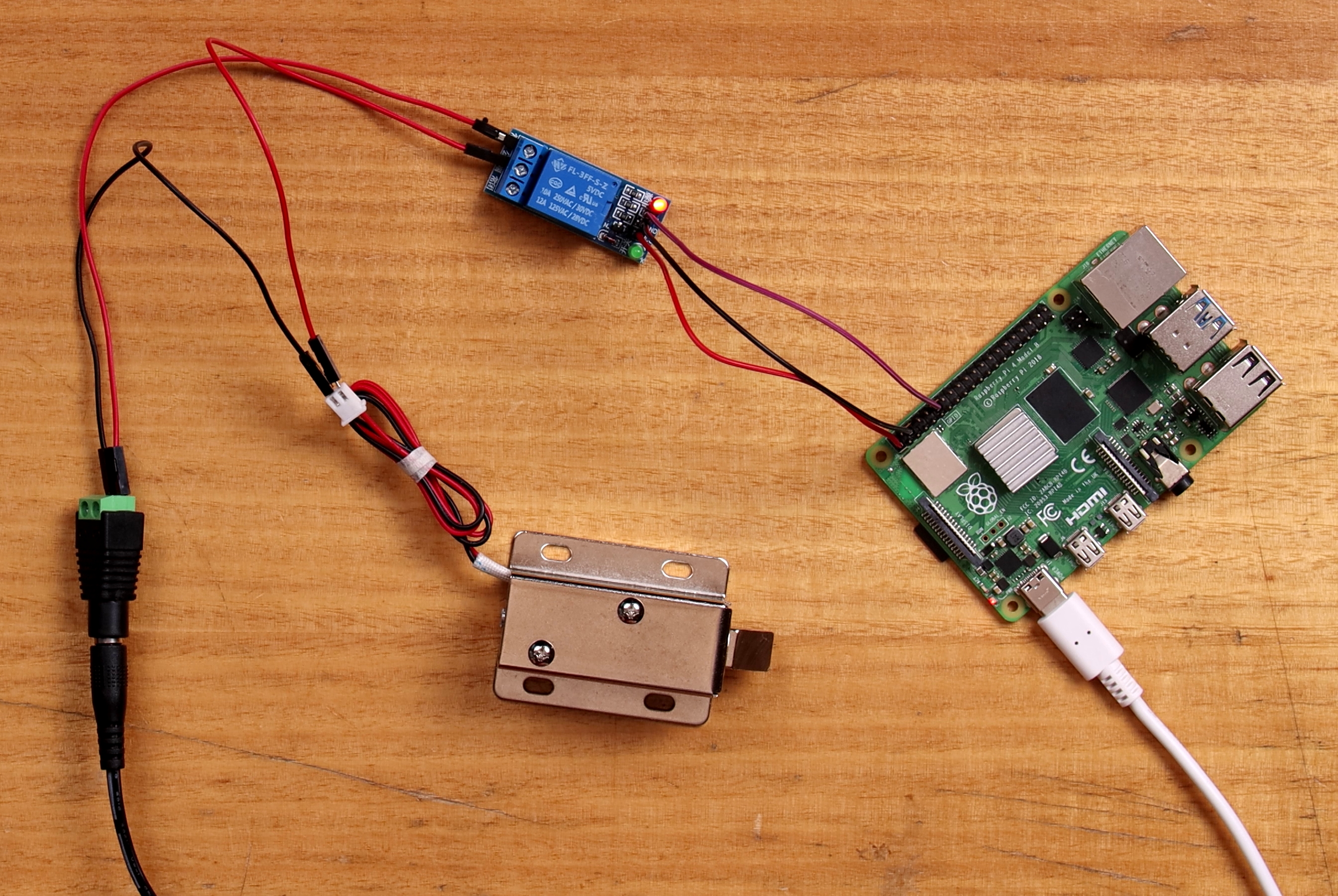
Below is an image of the final result of this guide! It is also true you can control solenoids more directly using a transistor, resistor and diode check out another guide linked down below on how to do that with a 5V solenoid and an Arduino Uno. Thus Solenoids of 5 Volts can be controlled and powered directly by a Raspberry Pi given the correct setup. A great tutorial on how to control a 5V solenoid with an Arduino as well as information on solenoids terminology can be found here.
As always if you have got any questions, queries, or things you'd like to see added please let us know your thoughts!
What You Need
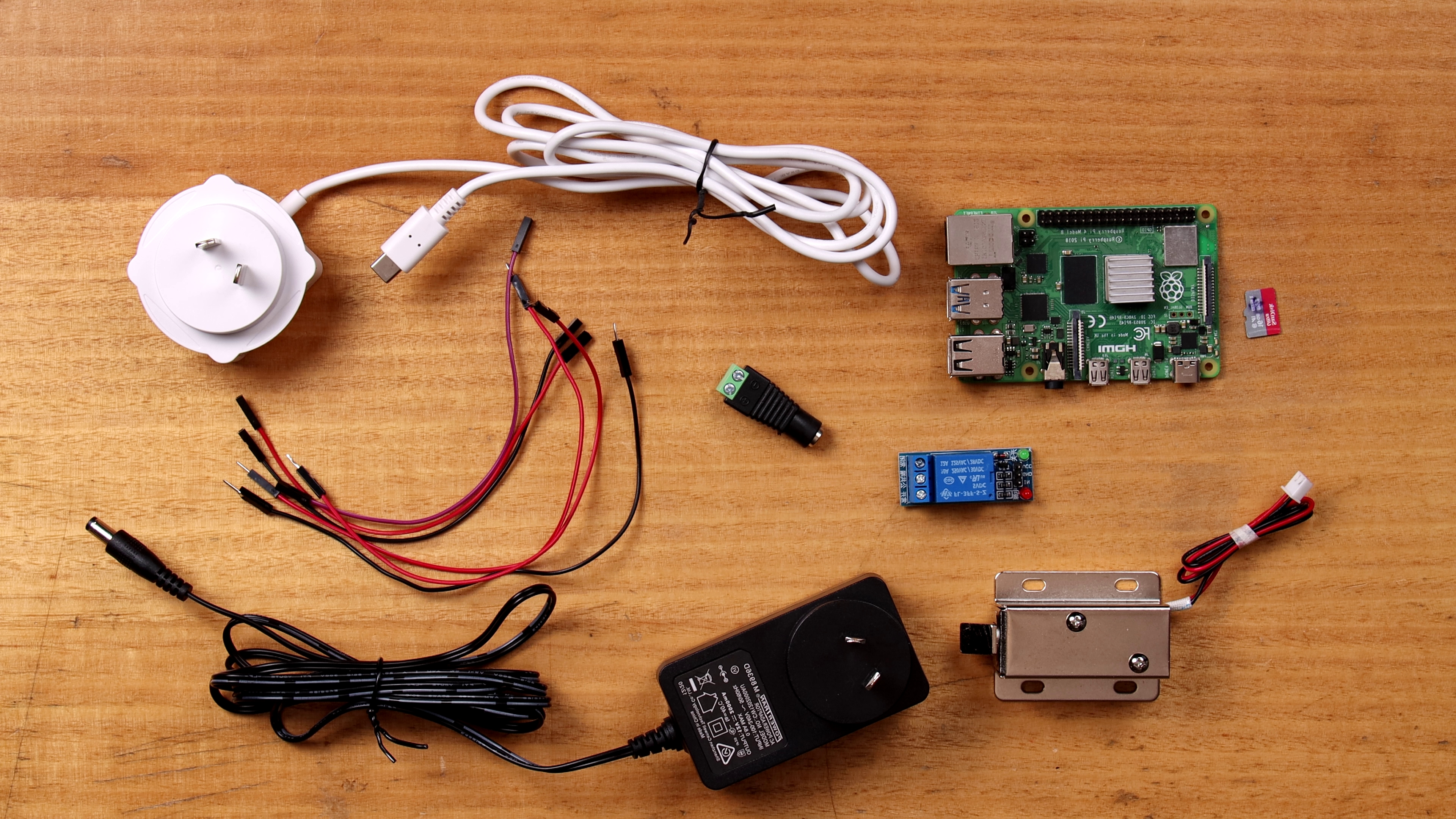
Below is an image of everything you need laying out on the table. Further below is a list of all these items.
Below is a list of everything you will need to recreate this with the images of most components below them. You will also want a small Philips head screwdriver.
- A Raspberry Pi with a Micro-SD Card Flashed with Raspberry PI OS (I use a Raspberry Pi 4 Model B but earlier Micro-Processor Raspberry Pi Boards can be used as well so long as you can get to the GPIO. It will be easier if it has headers already soldered on. A guide to flash Micro-SD cards can be found here)
- Raspberry Pi 4 Official Power Supply
- Solenoid 12V (The one I use here is for a latch/lock. There are also very cool Valve Solenoids if you want to control the flow of liquid)
- 5V Single Channel Relay Module 10A (If you want to control more you can use a Multi-Channel Relay instead just keep in mind current demands)
- 12V DC 2A Fixed 2.1mm Tip Appliance Plugpack
- Jumper Cables Male to Male and Female to Female
Schematics and Build
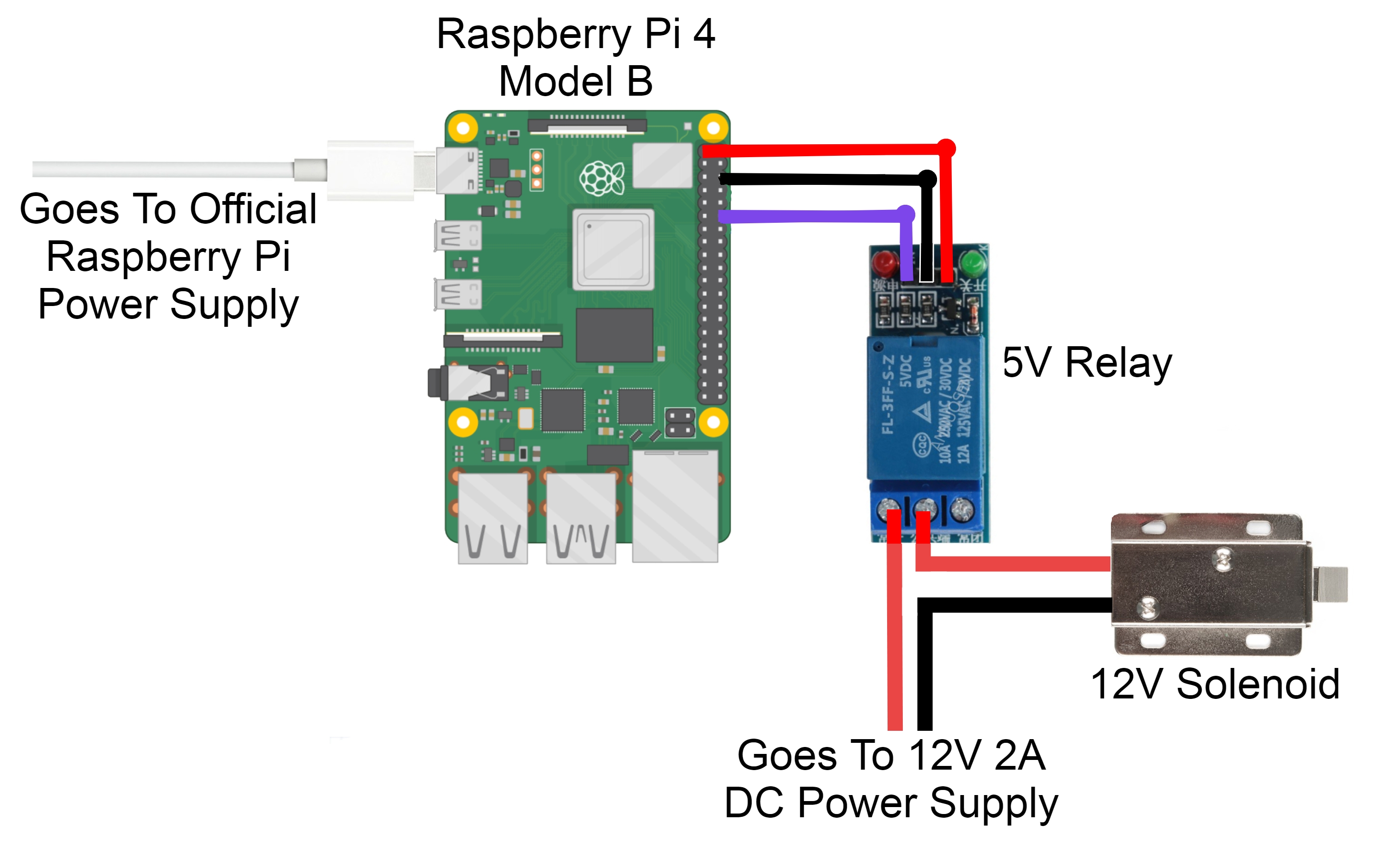
Below is an image of what and how we will connect these components together.
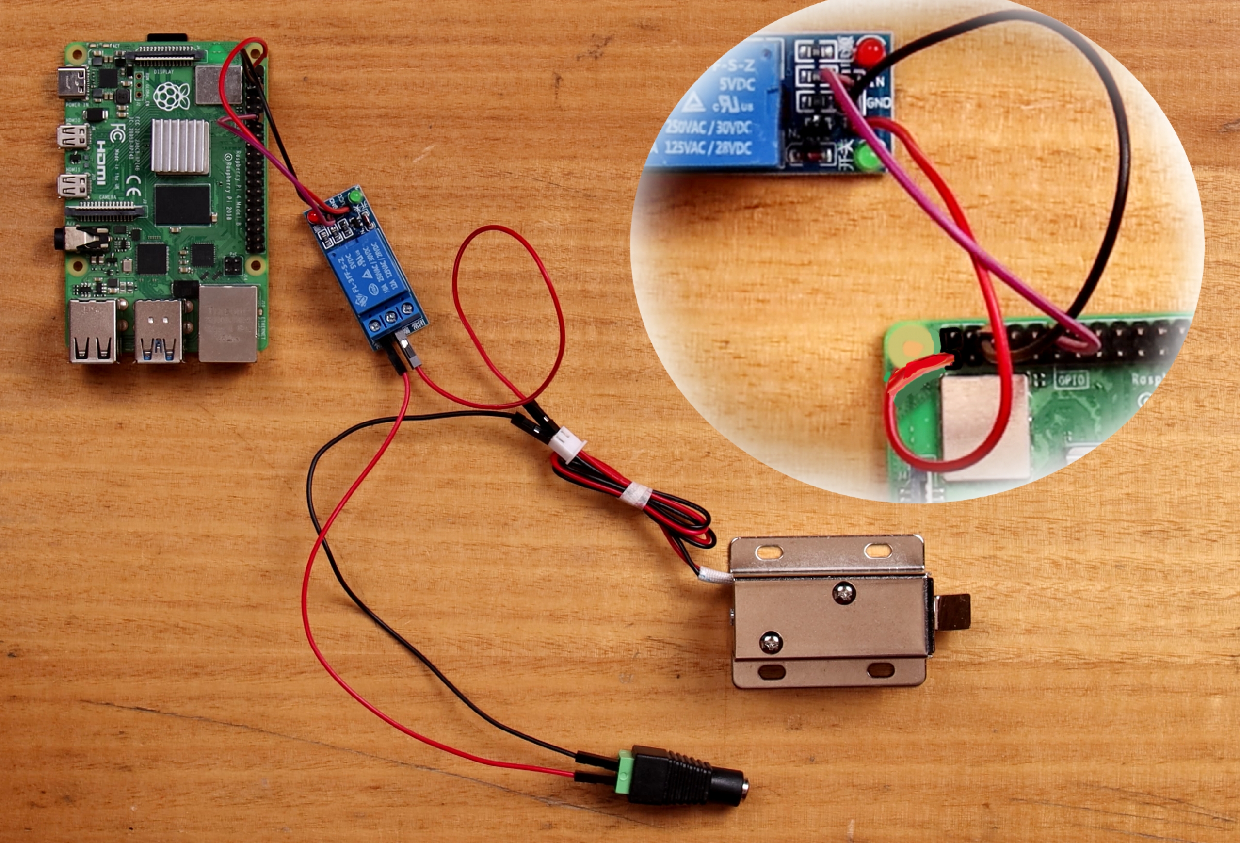
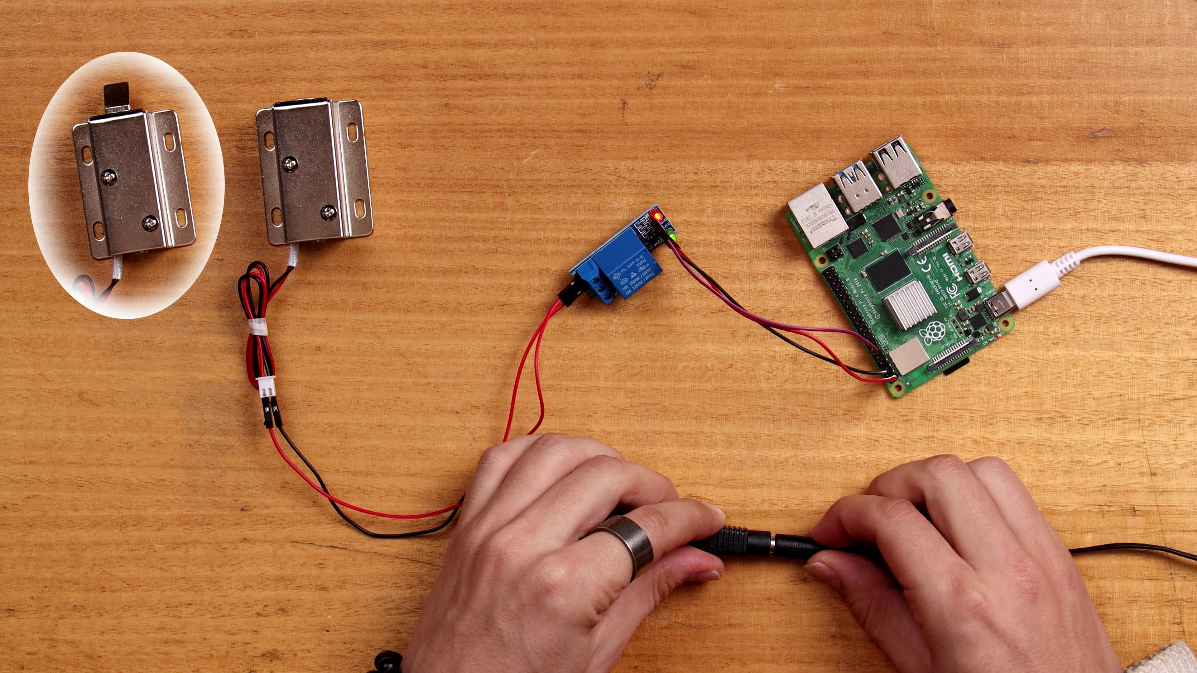
Connect the Ground Pin of the Raspberry Pi to the Ground Pin on the Relay. Connect the Vcc Volt Power to the 3.3 Volt Pin on the Raspberry Pi. For this I use the GPIO 18 (which is Pin Number 12) as the Data Pin telling the Relay either to open or close. Moving attention to the Solenoid attach a ground wire to the ground connection on the DC power jack by screwing it into place with a screwdriver. Then attach the Solenoid positive to the middle connection on the Relay and the positive side of the power jack to the pin on the top of the Relay by screwing them down. The top of the board is determined by following the orientation of the words printed on top of the blue box (which conceals the actual mechanical mechanism of the Relay). The pin on the bottom will be left empty. This arrangement means the solenoid will be unpowered unless the Relay is actuated by the Raspberry Pi.
Now before we add power to the system by connecting the two power supplies let's get the code into the Raspberry pi running. So once all of those are connected together using Jumper cables it will look a lot like the image below.
Code To Do It
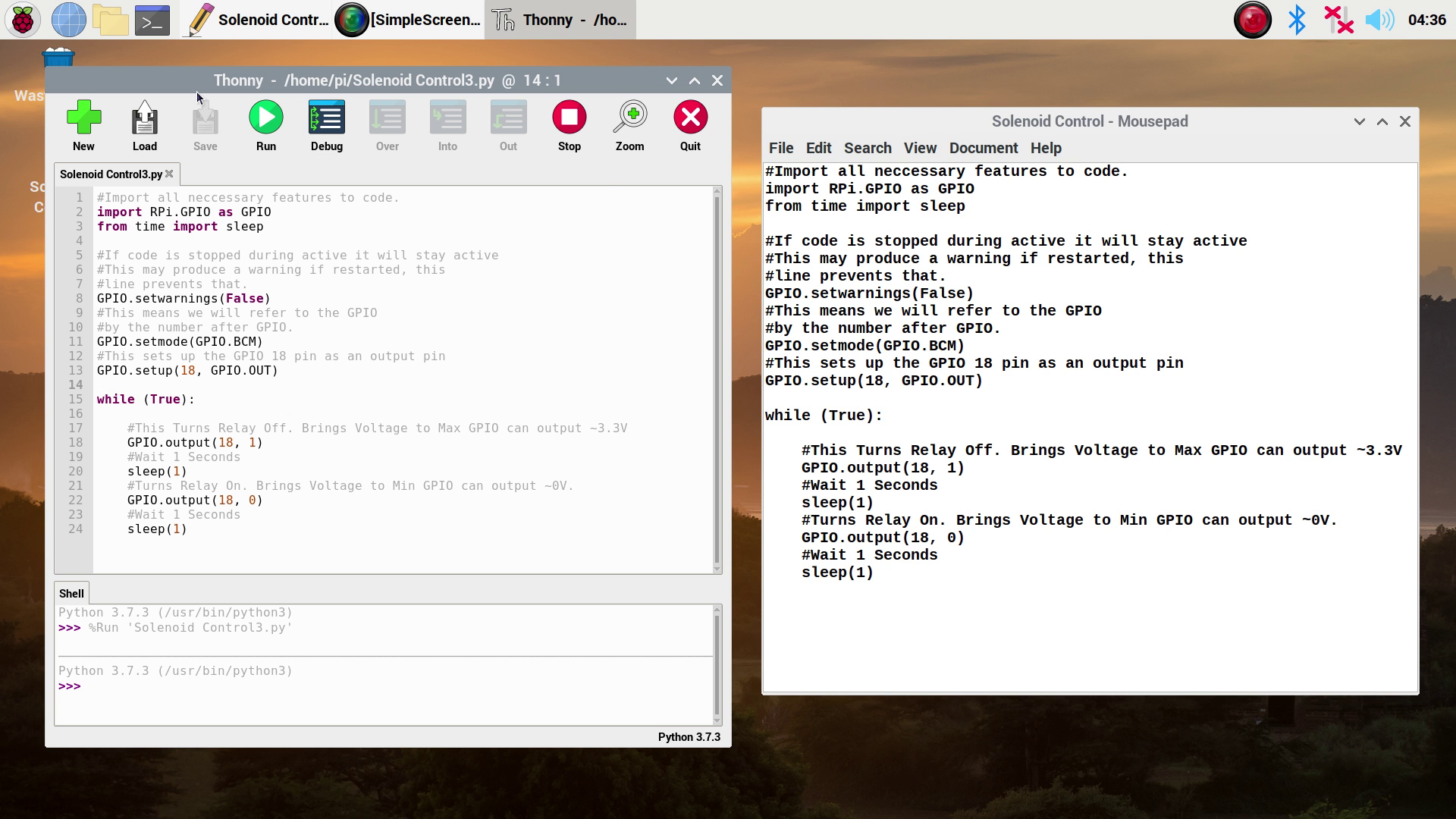
There are a lot of ways you can get the Raspberry Pi to activate this Solenoid. I will do the most intuitive by connecting this Raspberry Pi up to a monitor with a mouse and keyboard and directly writing code to it. Check out this guide if you need help doing this. So with those peripheries connected plug in that USB C and wait until you see that familiar Raspberry Pi background. Open up a Python interface like Thonny. Click on the Application Menu (this is the Raspberry Pi Symbol on the top left of the screen and hover over the Programming Tab to find them). Then copy and paste the following code into the coding area (you can also download this code at the bottom of the page).
#Import all neccessary features to code.
import RPi.GPIO as GPIO
from time import sleep

#If code is stopped while the solenoid is active it stays active
#This may produce a warning if the code is restarted and it finds the GPIO Pin, which it defines as non-active in next line, is still active
#from previous time the code was run. This line prevents that warning syntax popping up which if it did would stop the code running.
GPIO.setwarnings(False)
#This means we will refer to the GPIO pins
#by the number directly after the word GPIO. A good Pin Out Resource can be found here https://pinout.xyz/
GPIO.setmode(GPIO.BCM)
#This sets up the GPIO 18 pin as an output pin
GPIO.setup(18, GPIO.OUT)

while (True):

    #This Turns Relay Off. Brings Voltage to Max GPIO can output ~3.3V
    GPIO.output(18, 1)
    #Wait 1 Seconds
    sleep(1)
    #Turns Relay On. Brings Voltage to Min GPIO can output ~0V.
    GPIO.output(18, 0)
    #Wait 1 Seconds
    sleep(1)
Allow me to simply explain this code. The first two lines set up all the necessary information the script needs by importing functionality. It then removes GPIO warnings and then determines the way we refer to each GPIO pin (in this case by the number found after GPIO). Next, we make the GPIO 18 Pin be an output pin. Then it starts an infinite loop using a while (true): statement. This loop starts by setting the Output GPIO Pin 18 to high thus it sends out the max voltage. The max voltage it can send out is approximately 3.3Volts. This voltage will not trigger the relay and thus the Solenoid will remain deactivated. Next, the code will wait for a second. After that wait, the GPIO Pin 18 is turned to low thus is sends out the min voltage. This will send out the lowest voltage an output pin can. This is approximately 0 Volts). This will trigger the Relay to switch on thus activating the Solenoid. The Raspberry Pi will then wait for a second. This process is then repeated, opening and closing the solenoid each second. See below for what it looks like on the Raspberry Pi.
Let us save and run the code by pressing the big green button. Now plug in the power for the Solenoid, and just like that you should see the 12 Volt Solenoid moving back and forth each second. You will also be able to hear the Relay clicking on and off.
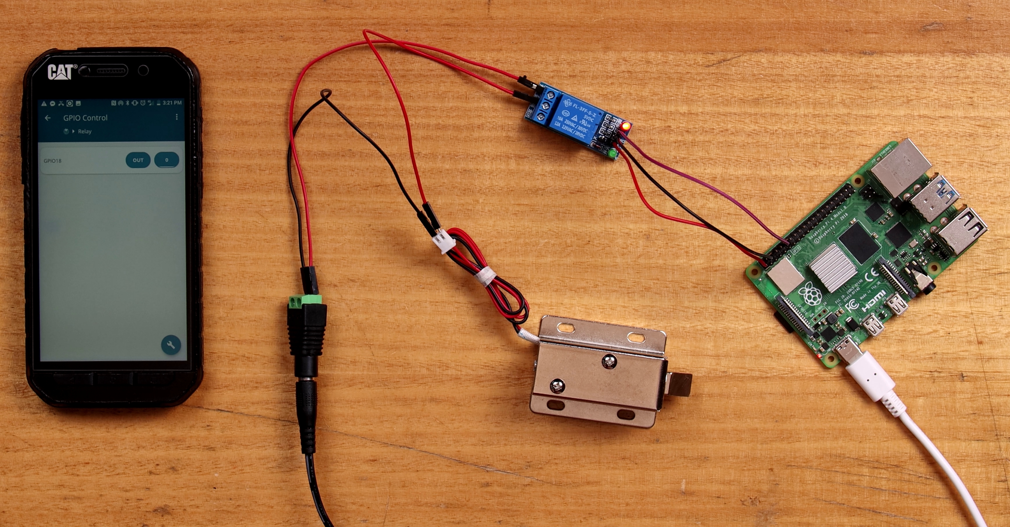
The code here you can alter to make whatever GPIO Pin you want to cause the Solenoid actuation for any manner of reasons or lengths of time. This is where real creativity can happen. Another good way of activating this GPIO pin remotely is by using your Phone and a Free app called RaspController, see me doing this below, link to that guide showing you how here.
Download The Code
Below you can find attached directly below the Python code for the Raspberry Pi all ready to go! For ideas where to go next just check out this https://www.youtube.com/watch?v=BmzRB2z45a8

