Love your Raspberry Pi but wish it had even more connectivity akin to your mobile phone. Then the Waveshare 4G HAT is the solution for you! HAT simply means Hardware attached On Top. With this installed on your Raspberry Pi Single Board Computer it will be able to connect to 4G, 3G, 2G, NB-IoT, or CAT-M1 Mobile Networks. You will require an Activated SIM Card to do this. This HAT also unlocks GNSS (Global Navigation Satellite System) Positioning to the apparatus thus your Raspberry Pi will be able to pinpoint its location no matter where it is in this Big Wide World.
This Waveshare 4G HAT has a SIM7600G-H Module onboard which enables the 4G/3G/2G communication and GNSS positioning. This module supports LTE CAT4 connection up to 150Mbps for downlink data transfer. If you are curious as to Where Your IoT (Internet of Things) Devices can Connect, check the linked guide
By the end of this guide, you will be able to send text messages and ring phones from your Raspberry Pi Single Board Computer. Furthermore, you will be to pinpoint exactly what location your device is via GPS (and then send that location data through a text message). You will also be able to send text messages (SMS) to your Raspberry Pi Single Board Computer which can then activate hardware (attached via GPIO Pins) based on the contents of the text message. See the contents of this guide below.
- What You Need
- Installing a Sim Card to Waveshare 4G HAT
- Hardware Assembly
- Making a Phone Call
- Figuring out your GPS Location
- Sending a Text with GPS Location
- What GPIO Pins are being Utilised by HAT
- Send a Text to your Raspberry Pi to Control GPIO Pins
- Downloads (Python Scripts and Mount STL) and a Note on AT Commands
You can also run this Waveshare 4G HAT as an Internet Hotspot, providing an internet connection that you can use to access the web or send out MQTT commands but to prevent blowing up the scope of this guide any larger, that will be explored in a follow-up guide. Furthermore, correctly configured this Waveshare 4G HAT will work with an Arduino Uno Micro-Controller or even as a standalone board, but that's also another story for another guide. If you are using a Raspberry Pi Zero/Zero W/Zero 2 W there is a Waveshare 4G HAT (B) Version built for the job. See the Waveshare 4G HAT assembled on top of a Raspberry Pi 4 Model B below which enables LTE Cat-4 4G/3G/2G communication and GNSS Positioning.
Now it is worth noting here, if you only want GPS location then you do not need to have a SIM Card installed in this system. Think of the many GPS satellites that orbit around our Earth as shouting clocks that travel at ~4km/s. Once your device has heard enough of them (and figured out how long it took for that shout to get to the device) it can then perform trilateration calculations. After some clever maths (that all happens in the background) your device will then pinpoint its exact position on Earth. There are other modules that will do this for you (without adding 4G connectivity) such as this GPS Receiver - GP-735 or the Adafruit Ultimate GPS Breakout.
Nevertheless, if you want a product that cant be sold in Iran, North Korea, Cuba, Sudan, or Syria because it is too useful, then I got you. As always if you have any questions, queries, or things to add please let us know your thoughts!
What You Need
Below is everything you will need for this guide.
- Raspberry Pi 4 Model B (in my case I have used a Raspberry Pi 4 Model B 2GB but worth noting this HAT will work with all same form factor Raspberry Pi Single Board Computers)
- Waveshare 4G HAT for Raspberry Pi
- Activated SIM Card (If you choose to forgo Phone calls the Hologram Global IOT SIM is a good solution, take the time to figure out the right plan for your situation)
- Micro-SD Card with Raspberry Pi OS
- Micro-HDMI to HDMI Cord and Monitor
- Power Supply
- Mouse and Keyboard
- USB Microphone and Audio Headphones (Optional)
Installing a SIM card to Waveshare 4G HAT
The first step is getting your hands on a SIM (Subscriber Identity Module) card. In regards to specifications, you want a SIM card that will work on 4G Networks. I have a prepaid version that allows texts, phone calls, and mobile data. If you want to forgo Phone calls the Hologram Global IoT SIM Card might be the perfect solution for you, just take the time to figure out the right plan for your situation.
In recent years (at least within Australia) you now need to provide identification to get your hands on a SIM from the big Telecommunication brands. Then they go into a locked safe room, pull one out for you, and triple-check that its existence has been weaved completely into your name (and has been activated). It took me a good 20 minutes to get my hands on one, so take that as a forewarning. Make sure they write down the Phone Number that the SIM card is provided with.
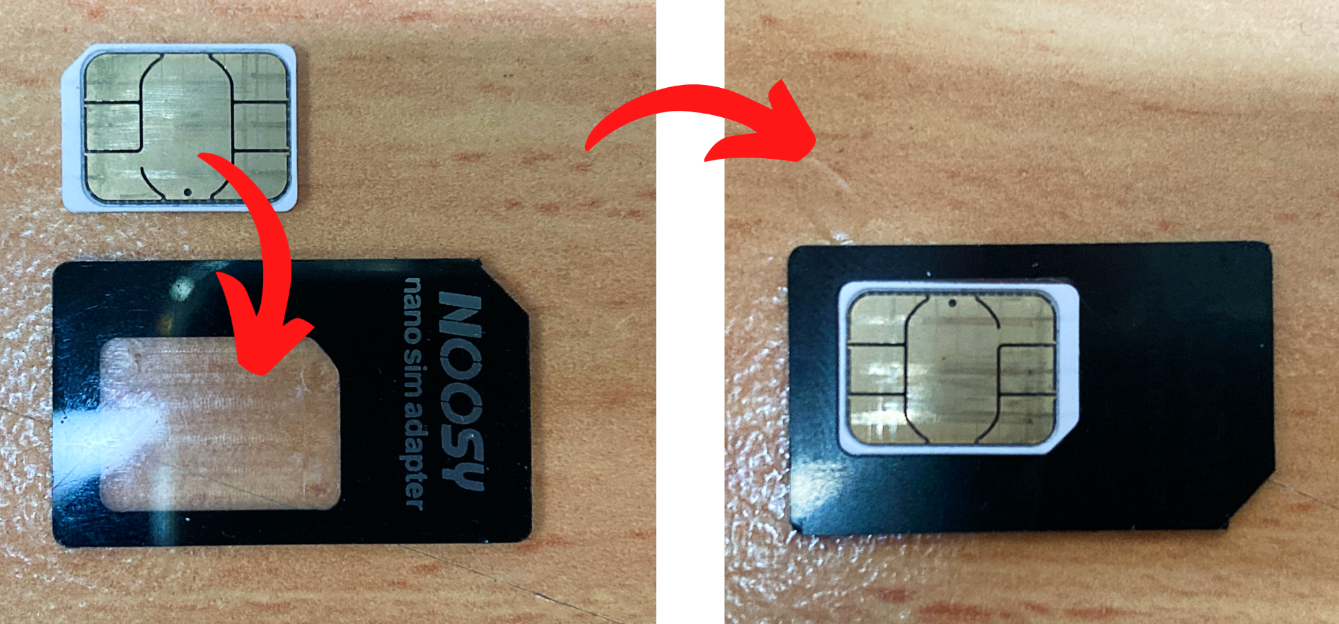
Once you do have your hands on a SIM make sure it is the right size. You will need to use a Standard Size SIM but if you have a different size you can use a SIM Card Adapter which can be found here. See a Nano SIM card fitting into the adapter in the image below.
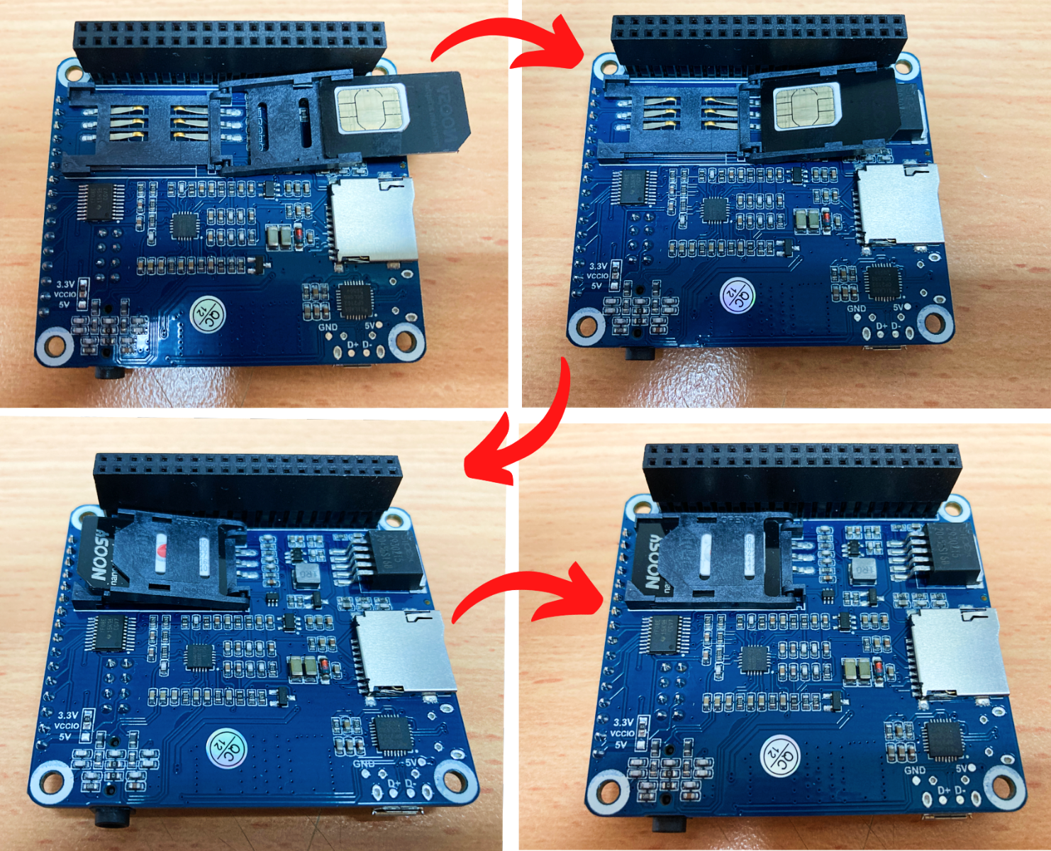
The Waveshare 4G HAT has a clever locking system that is a lot easier to use when you have the know-how. When presented with the default closed position be aware that you need to slide back the mechanism to unlock it. Then it will be able to swing open. No major force is required in any step of this. Slip the SIM card into the cradle and be careful that the SIM card does not fall out/shuffle around during installation. If you are feeling unsure of how to do this, check the above video of the installation or the step-by-step process seen in the image below.
Hardware Assembly
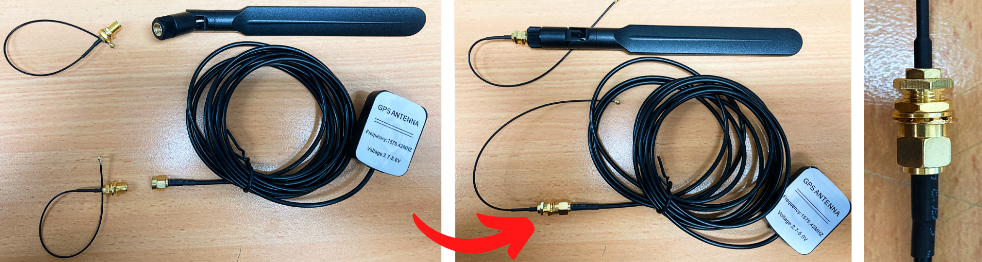
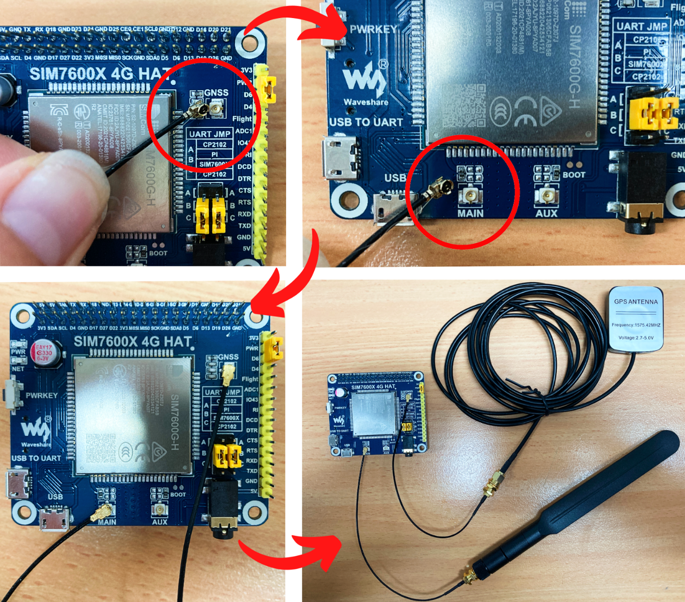
Theres a couple of steps for assembly. Let's start by connecting the wires from the GLONASS (GPS) Antenna and the 4G Mobile Network Antenna to the u.FL Adapter Connectors. See this happening in the image below.
Once complete connect the other side of the two u.FL connectors to the top of the HAT. Connect the | GNSS | port to the GPS Antenna and the | MAIN | port to the Mobile Network Antenna. All connections are marked on the board. Line up them up over the top of the connection and push down firmly and with commitment. It will then pop/click firmly into place. Is good practise to do this on top of foam/silicon matt for support. These connections are not easy to remove, so double-check the location you are attaching it, do it once and do it right. See these connections happening in the image below.
Be aware not to tug or accidentally pull off the Antennas when you are moving around the setup. Having a case that holds the antenna upright, securely, and nearby is definitely advantageous.
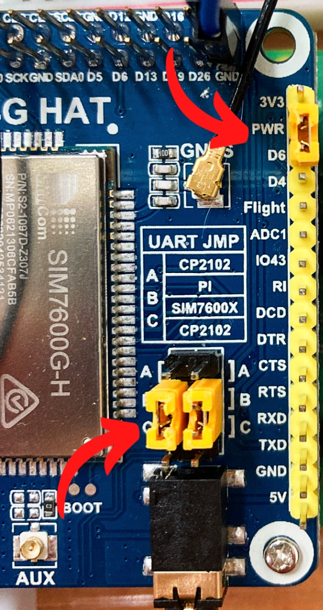
Now turn your attention to the Yellow Jumper Caps on the top of the Waveshare 4G HAT. Adjusting the Jumper Caps on this Waveshare 4G HAT Board, by carefully pulling them off the pins and putting them back in the right place, will enable it to work with a Raspberry Pi Single Board Computer. Other Jumper Cap arrangements configure this HAT to work with other boards (like Arduino Micro-Controllers). Setting the Yellow Jumper Cap between | PWR | and | D6 | pins, as you can see in the image below, will allow the Raspberry Pi the ability to turn on/off the Waveshare 4G Hat. Also, arrange the pair of Yellow Jumpers Caps so that they look like the image below connecting | PI | row down to | SIM7600X |.
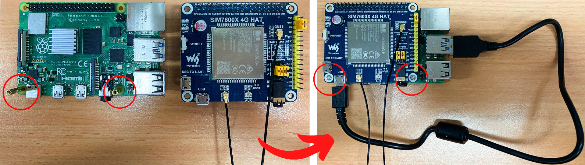
Mount the 4G HAT to the Raspberry Pi Board as you would any HAT using the attached hardware. Make sure the GPIO pins line up correctly and press the two boards firmly together. Then plug in USB micro (POWER) to the bottom USB3.0 port of Raspberry Pi.
Then just set up Raspberry Pi as a desktop computer. Keyboard, Micro-SD card flashed with Raspberry Pi OS, Micro-HDMI to Monitor and finish by providing power to the Raspberry Pi through the USB-C port. I have included a USB Microphone which plugged directly into a USB2.0 port. This is all the hardware assembly that this setup will need to work.
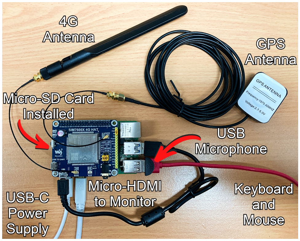
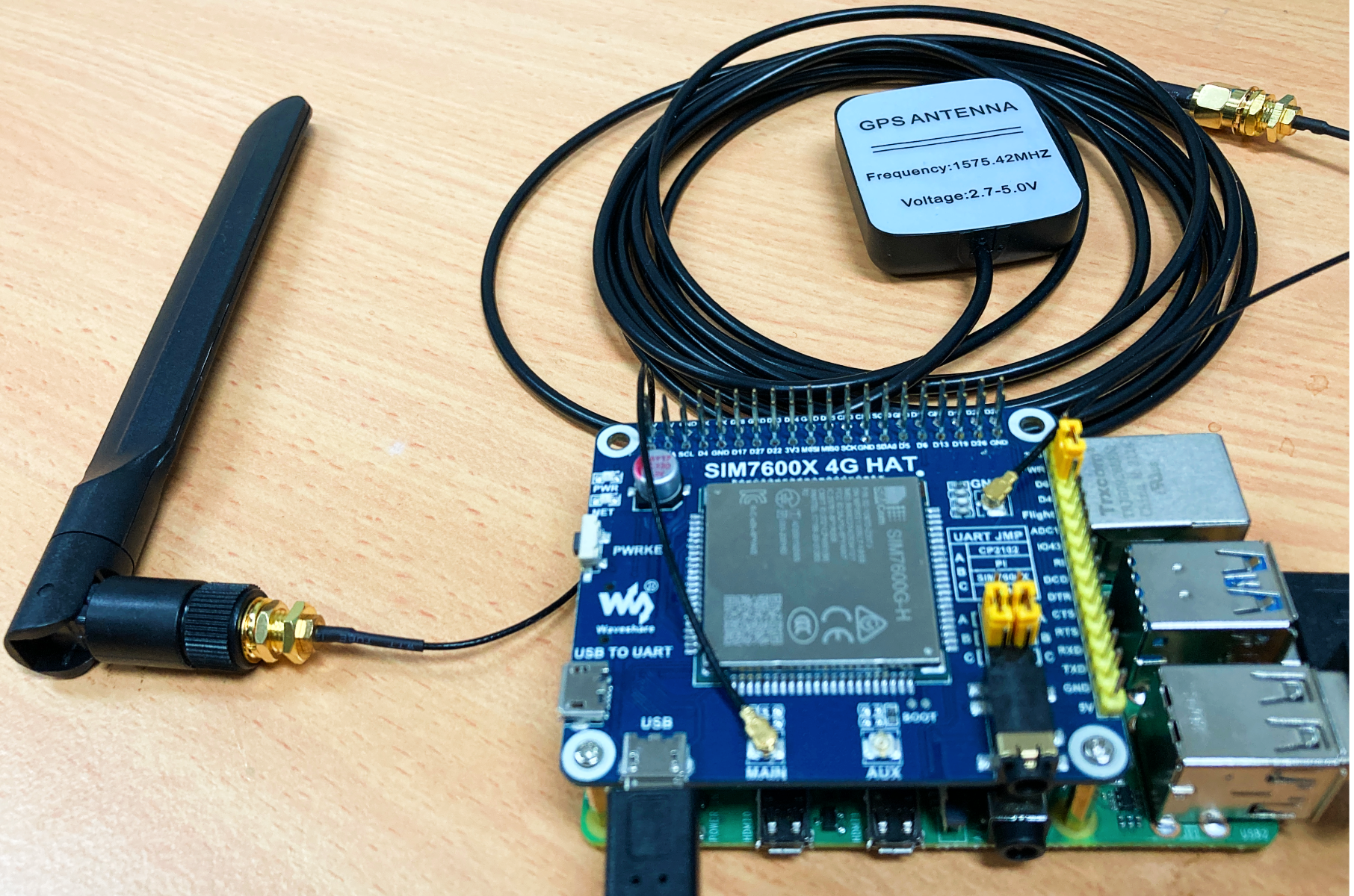
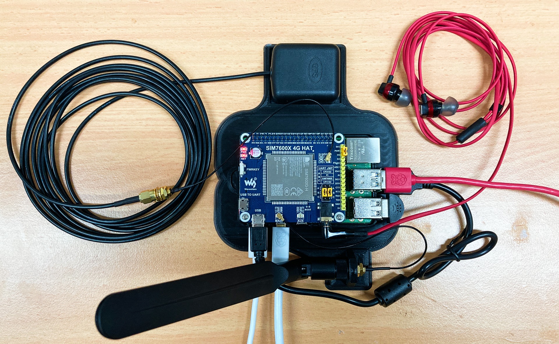
I 3D printed a mount to set everything onto securely and to make sure the 4G Antenna stand up straight. I also added some headphones to the Auxilary port of the Waveshare 4G HAT. See this assembled in the image below. You can print this too if you'd like, find the download link for it here.
Software Configuration
This 4G Waveshare HAT is a very clever bit of technology but it does require some software set up so that it can communicate effectively and function with the Raspberry Pi Single Board Computer.
With our Raspberry Pi connected as a Desktop computer with the power to the system, it will boot up to Raspberry Pi OS. There is a first boot wizard now. It will enable you to set your country, language, and timezone, change the default password, make sure the screen is set up correctly, make sure you are connected to a WIFI network, and fully update the software. It is very intuitive and once complete your Raspberry Pi system will reboot itself. See the start page of this first boot wizard below.

Thus upon the completion of rebooting the Raspberry Pi Desktop Screen should welcome you. Once here open up a new Terminal Window by pressing the black button on the top left of the screen, see the location of this (highlighted with a red box) in the below image. In this terminal window type and enter the following.
sudo raspi-config
As soon as you press enter it will open the configuration menu (old school graphics but super incredible and useful). Use the arrow keys to navigate to |Interface Options| and press enter. This will take you into a deeper menu, which you can see in the image below. In this menu, we will Enable Serial Port Communication. This is how the Raspberry Pi Single Board Computer and the Waveshare 4G HAT are going to communicate. Use the arrow keys to navigate down to | Serial Port | and press enter. This will open up a new menu page asking the question | Would you like a login shell to be accessible over serial? |, navigate to and type the Enter key on |No|. It will then open up another menu page asking the question |Would you like the serial port hardware to be enabled?|, navigate to and type the Enter key on |Yes|. With that complete navigate to and type enter on| Finish |. See all this happening in the image below.

When the prompt asks you to reboot do so. Now we will install Minicom to our Raspberry Pi system. Once again open a Terminal Window using that black button on the top left of the screen. Then with it open, type and enter the following into the new terminal window.
sudo apt-get install minicom
If ever prompted, “Do you want to continue? (y/n)” press Y and then the Enter key to continue the process. See that question being asked in the below image.

Next, to install the Demo codes open up a new Terminal Window using the black button on the top left of the screen. Then type and enter the following to download a zip file of all the example codes and drivers to make this Waveshare 4G HAT operate. See this command written in the terminal window in the image below.
wget https://www.waveshare.com/w/upload/2/29/SIM7600X-4G-HAT-Demo.7z

When that completes, use the same Terminal Window to type and enter each of the following commands one by one. The first will install 7-Zip software which we will use to unzip the downloaded file. The second line will unzip our downloaded file into a specific location. The third line will provide permissions so that Raspberry Pi OS doesn't block the Waveshare 4G HAT from functioning. The final will open up a the | rc.local | file which we will edit.
sudo apt-get install p7zip-full
7z x SIM7600X-4G-HAT-Demo.7z -r -o/home/pi
sudo chmod 777 -R /home/pi/SIM7600X-4G-HAT-Demo
sudo nano /etc/rc.local
This last line when entered will open up a new page (the | rc.local | file) that you can navigate around by using the arrow keys on your keyboard. You will need to add a command inside the | rc.local | file. Find this command directly below so that it is easier to copy and paste. It will need to be located exactly as I have done in the below image. Right click the image and open it in a new tab to see the image in full size if you need it. Completing this task will mean that the Waveshare 4G HAT drivers will start on the boot-up of the Raspberry Pi Single Board Computer.
sh /home/pi/SIM7600X-4G-HAT-Demo/Raspberry/c/sim7600_4G_hat_init

Having done this use your keyboard press Ctrl-X, Y, and then Enter Key to lock in and save these changes.
With that completed open up a new terminal window then type and enter each of the following commands one by one. The first line will direct focus to the | bcm2835 | folder which has the Waveshare 4G HAT driver inside. The second command will give access permissions and initialise the driver. See the results of entering these commands in the image below.
cd /home/pi/SIM7600X-4G-HAT-Demo/Raspberry/c/bcm2835
chmod +x configure && ./configure && sudo make && sudo make install

This will run some make/configure scripts. When completed we have fully set up this Waveshare 4G HAT to work with the Raspberry Pi Single Board Computer. Also we have some great example Python Scripts that we can jump into and start exploring!
Making a Phone Call
So lets call up a mobile phone using the Raspberry Pi System that we have set up! Open up the script | PhoneCall.py | you can find it in the directory | /home/pi/SIM7600X-4G-HAT-Demo/Raspberry/Python/PhoneCall |. To open the file explorer press the yellow folder button on the top left of the screen. See this location below.

Right-click this file and select open with Thonny IDE. Thonny IDE is just a Python Interpreter Software and you can use any that takes your preference. With the file open adjust the default phone number to the one you want to call. Also double-check that the line | ser = serial.Serial('/dev/ttyS0',115200) | is written the same on your script. The ttyS0 is the User UART Connection Port of Raspberry Pi 3B, 3B+ and Raspberry Pi 4 Model B. The User UART Connection for a Raspberry Pi 2B/Zero is ttyAMA0. If your using one of those single board computers make sure to adjust the script appropriately. See this happening in the image below.

With that complete and some headphones attached to the Waveshare Auxillary Port, we are ready. Press the big green | Run | button on the script. Give it a little second or two to initialise and Budda Boom. Your target phone should be receiving a call from your Raspberry Pi, see this happening in the image below. If you pick up the call should last less than 20 seconds (as decided in the Python script). Success! You have done it and called your mobile phone via your Raspberry Pi Single Board Computer. It is also great confirmation that the Waveshare 4G HAT has connected correctly to the mobile network as it should.

Figuring out GPS Location
Trilateration is pretty swell. In combination with a GPS Receiver, we can use it to calculate the exact positioning of the device on the Earth's surface. It is the exact same method your Smart Phone utilises for its GPS. Aidan did a great guide on How GPS Receivers Work so hit that up if you're curious. So let's now get our Raspberry Pi to pinpoint its exact location.
A great example script that we can dip our toes into this world is called | GPS.py | which you can find in the directory | /home/pi/SIM7600X-4G-HAT-Demo/Raspberry/Python/GPS |. See this location below.

This script will activate and utilise the GPS Antenna. You can do this without a SIM card.
With the script open click the green | Run | button. and allow it a couple of minutes to figure out where in the world the Raspberry Pi is. See this happening in the image below, it prints out the GPS Data straight to the Python Shell every few seconds.

If you are running into issues with connections place the GPS receiver's sticker side face down and outside. Also, note that it can have connectivity issues in rainy weather. It took about 4 minutes for me to receive the positioning signal after running the | GPS.py | script initially.
Now this default Python script is fantastic however it provides the location details in NMEA format. NMEA is a standard data format supported by all GPS manufacturers but it isn't very human-readable. I created another script called | GPS-Human-Readable.py | which you can download at the bottom of this page (as well as any other scripts talked about in this guide). Opening and running this script in the same way as before will results in two values, Lattitude and Longitude, given in Decimal Degrees format. Copy and paste these results into the Google Maps search bar and it will refresh the webpage to exactly where your Raspberry Pi device is located. See this both happening in the image below.

Sending a Text with GPS Location
So now we know that our Raspberry Pi Single Board Computer is connected to both the Mobile Network and the GPS (GLONASS) System. So lets use both! I have created a script that will figure out the GPS location of the device and then send an SMS from our Raspberry Pi Single board computer that has our pinpointed GPS location as the contents of the message. This SMS is written in very human-readable language.
To do this open up the script | FindGPSthenSMSFinal.py | by right-clicking it and opening it with Thonny IDE. You can download this script (as well as any other scripts talked about in this guide) in the download section at the bottom of this guide. This Python script was created by combining the two demo scripts talked about above.
You will need to customise the Python Script by adding your Target Phone Number. With that done and it open like the image below, press the green | Run | button. As soon as you do it will start the GPS session and pinpoint its location in Latitude and Longitude, formated in decimal degrees. Decimal degrees (DD) is a notation for expressing latitude and longitude geographic coordinates as decimal fractions of a degree. Once it finds the GPS location it will swap to SMS mode and send the message through to your target Phone.

And Badda boom! That’s how that is done. This Python script could be scheduled to run on boot or at a certain point each day. So long as you are providing power to the system it would make for a perfectly capable DIY GPS tracking system for fleet management.
The Demo Scripts are great platforms to spring from and create custom Python scripts. Sent data doesn't need to just be GPS locations. Any kind of temperature, gas, distance, colour, motion, lux, or environmental sensor (just to name a few) can be attached to a Raspberry Pi Single Board Computer and we have guides for them all. Then to have that sensor data sent through SMS can be achieved in a very similar manner to the above. Knowledge is Power, Data is the Core of it and now you can send that Data to the furthest corners of this Earth.
What GPIO Pins are being Utilised by HAT
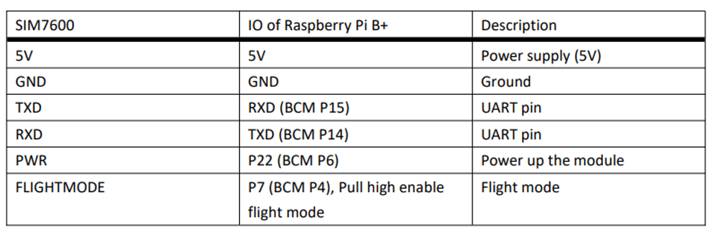
The default relationship between SIM7600 control pins (the brainbox on top of the Waveshare 4G HAT) and Raspberry Pi IOs is shown in the below image. This is important to know before attaching extra hardware to the GPIO Pins on the Raspberry Pi. You won't be able to connect to GPIO Pins that already have communication/powering tasks to perform. If you want a GPIO Pin Outs for Raspberry Pi Single Board Computers check out this repository here.
Send a Text to your Raspberry Pi to Control GPIO Pins
The GPIO (General Purpose Input and Output) Pins on the Raspberry Pi are the doorway to controlling and monitoring the outside world. They are able to control almost an endless amount of sensors, motors, actuators, and other hardware. So let us take advantage of this now and use the SMS receiving capability of our system to control the hardware attached to the GPIO Pins.
For today we will control a LED to turn on when a new text message (SMS) is received by the device which has the correct Keyword inside it. The script that will do this for us is called | GPIO-LED-Control-Via-Text.py |. You can also set up the Python script to only activate when an authorised number sends the SMS. That way if a different number sends the SMS message with the keyword it won't activate. Be aware that this LED is a placeholder for whatever hardware you want to use, be it a servo, solenoid, or motor, just as some examples.
So we now know exactly what GPIO pins we can or can’t use by the previous section (as certain GPIO pins are required by the Waveshare 4G HAT and Raspberry Pi to Communicate).
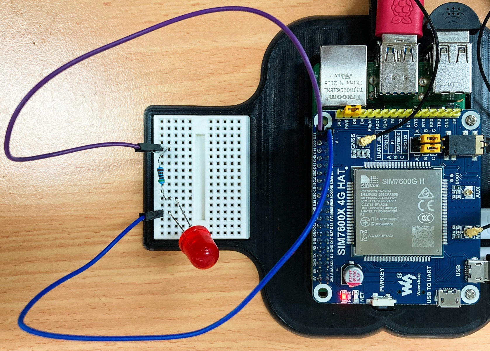
Wire up a Red LED Diode (with resistors in series so as not to burn out the LED) on top of a breadboard and attach the negative side to the Ground Pin (39) and the positive side to GPIO 21 Pin (40) on the Raspberry Pi. The LEDs longer leg is the Positive side (you can remember this because you need a longer length of material to cut and form a Positive Sign, +). A great guide to clarify at a grassroots level the LED Control code in the below Script and why certain connections are made can be found in Chapter 2 of the Raspberry Pi Workshop. See an image of the setup attached to our system below, Purple wire is Positive and the Blue wire is Negative.
At the bottom of this page is a download for all the scripts used in this guide. The one I refer to in this section is called | GPIO-LED-Control-Via-Text.py |. Open up this up with Thonny IDE and run it. This will continue running in the background, constantly looking for new SMS messages, opening up every new SMS message, printing all the details of the SMS to the shell, and checking it for the Keyword | red | in the contents. See this Python Script happening in the image below.
Now with that script continuing in the background SMS your Raspberry Pi Single-Board Computer a message with the string | red | somewhere in it. If you are new to the terminology string check out this guide right here. The script will recognise that a New Text has been sent and scan through it for any line of text (string) that matches its known keywords. If it finds | red | inside the Text message it will turn on the Red LED for 3 seconds. Keep in mind this is case-sensitive the keyword | RED | won't work. See the LED turn on from the SMS message in the image below.

This means so long as we are within Mobile connectivity (near everywhere, except for when you need it) we can now get our Raspberry Pi to start, stop and control almost any electronics. All open-source, jump in and add whatever you desire. Hopefully it will serve you well!
| For more SMS functionality, read Dave's post on the Core Electronics Forum. Dave has created a project to send SMS shell commands to a Raspberry Pi. Links to Dave's GitHub and instructions for following along can be found at the post. |
Downloads (Python Scripts and Mount STL) and a Note on AT Commands
If you start customising the Python Scripts you will eventually find yourself needing to know some knowledge on AT Commands. AT is the abbreviation for Attention (also referred to as Hayes Command Set) and is used in Modem or Mobile Phone chips to facilitate machine communications. Your Raspberry Pi and Waveshare 4G HAT will be sending AT commands back and forth every time you run any of this guide's Python Scripts. Depending on what you want your system to be it may just be a change in AT command. A great repository of AT commands can be found at the Engineers Garage here. Another great resource on explaining AT commands that I utilised was DevelopersHome Section on them found here. If you fill up your SIM card full of SMS Messages the command | AT+CMGD=[,4] | will delete all the SMS messages. You can enter this directly to the Raspberry Pi using Minicom. You won't be able to see what your typing unless you type and enter | ATE1 |. There's a great explanation on using Minicom and AT Commands here by Twilio. Here is the Original 4G Waveshare Manual for this HAT which is crammed full of information as well.
The STL file for the Raspberry Pi 4 Model B and Waveshare 4G HAT mount is in the zip file below. Also inside the zip file is all the Python scripts utilised in this guide. Download them and extract them to use them.

