This guide will teach you how to control any small and big servos with a Raspberry Pi 4 Model B (worth noting any Raspberry Pi Board with GPIO pins can be able to be used in this scenario. Servos are an immensely useful way to turn electrical energy into a rotational or linear motion with high efficiency and with great precision. The ones in this guide are all Standard Rotary Actuator Servos that can rotate 180 degrees or 270 degrees. Precise control over the narrow range (degrees of movement) is achieved through position. Information on the desired position is sent through via a PWM signal. The servos implemented in this guide would be desired or readily come across by a maker. The code supplied here will work with most Rotary Actuator Servos and can be adjusted to maximise the result with all. Worth noting that there are also similar-looking Continuous Rotation Servos. Those servos can spin continuously and are controlled by a Raspberry Pi differently with control over the speed and direction instead of position.
- What You Need
- Schematics and Build
- Code To Do It
- Download Code and Datasheets for the Servos Utilised
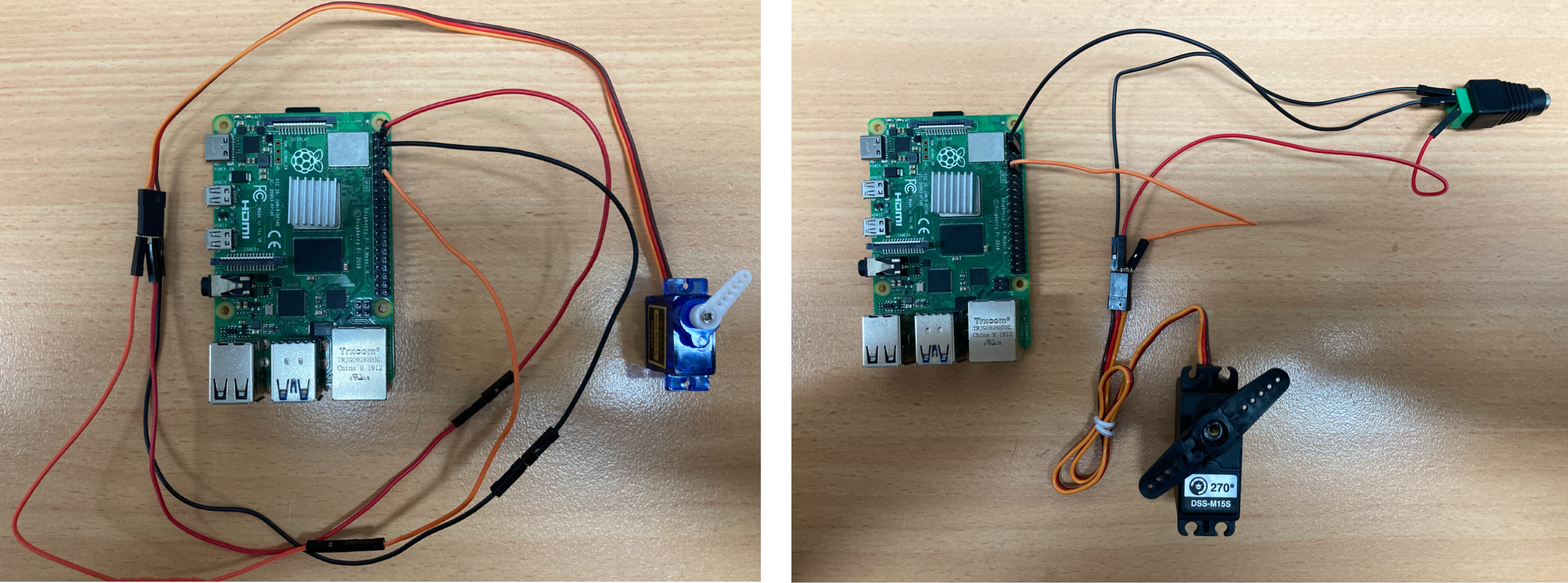
We will use an official Raspberry Pi Power Supply for power to the Raspberry Pi but when using the Larger Servo we will supply it with a 5V DC 4A Power supply as it will draw more current. Below is an image of the two final results of this guide!
If you want to power a whole bunch of servos (16!) simultaneously take a look at this as it will make your Raspberry Pi capable of controlling 16 servos simultaneously while taking up only 2 GPIO pins. You will need to do some light through-hole soldering to attach the headers onto the HAT circuit board. For another really cool product that incorporates servos (in an arrangement ideal to create a CCTV system) check out the Pimoroni Picade Pan-Tilt Hat.
Servo motors are part of a closed-loop system and are comprised of several parts namely a control circuit, servo motor, shaft, potentiometer, drive gears, amplifier, and either an encoder or resolver, check out below to see the common internal locations of these components.
As always if you have got any questions, queries, or things you'd like to see added please let us know your thoughts!
What You Need
Below is a list of everything you will need to recreate this with the images of most components below them. You will also want a small Philips head screwdriver to easily connect the DC Barrel Jack Adapter to the Jumper Cables.
- A Raspberry Pi with a Micro-SD Card Flashed with Raspberry PI OS (I use a Raspberry Pi 4 Model B but earlier Micro-Processor Raspberry Pi Boards can be used as well so long as you can get to the GPIO. It will be easier if it has headers already soldered on. A guide to flash Micro-SD cards can be found here)
- Raspberry Pi 4 Official Power Supply
- A Small Servo, the MakeBlock 9g Micro Servo Servo can turn 180 degrees in total. Another good 9g Servo is made by DFRobot.
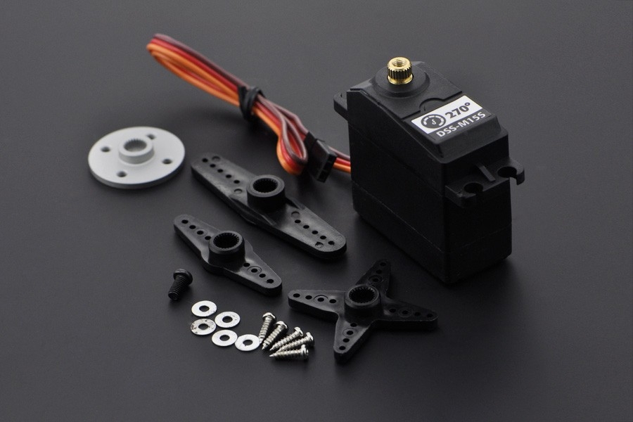
- A Large Servo, the DFRobot Metal Geared 15 KG Servo here can turn 270 degrees. Also here is a Servo that can rotate 300 degrees and has a clutch!
- 5V DC 4A Power Supply for use with the Large Servo as the Raspberry Pi GPIO Pin will not supply enough current to activate the Large Servo.
- DC Barrel Jack Adapter for use with the 5V DC 4A Plugpack.
And that is all you will need. If you wanted to use only one Power plug you can incorporate a 2-way 2.1mm DC Barrel Jack Splitter and a DC to USB Type-C Adapter. Attach the barrel jack splitter to the DC Power Supply and have one end power the Raspberry Pi through the USB-C and the other side Power the Servo.
Schematics and Build
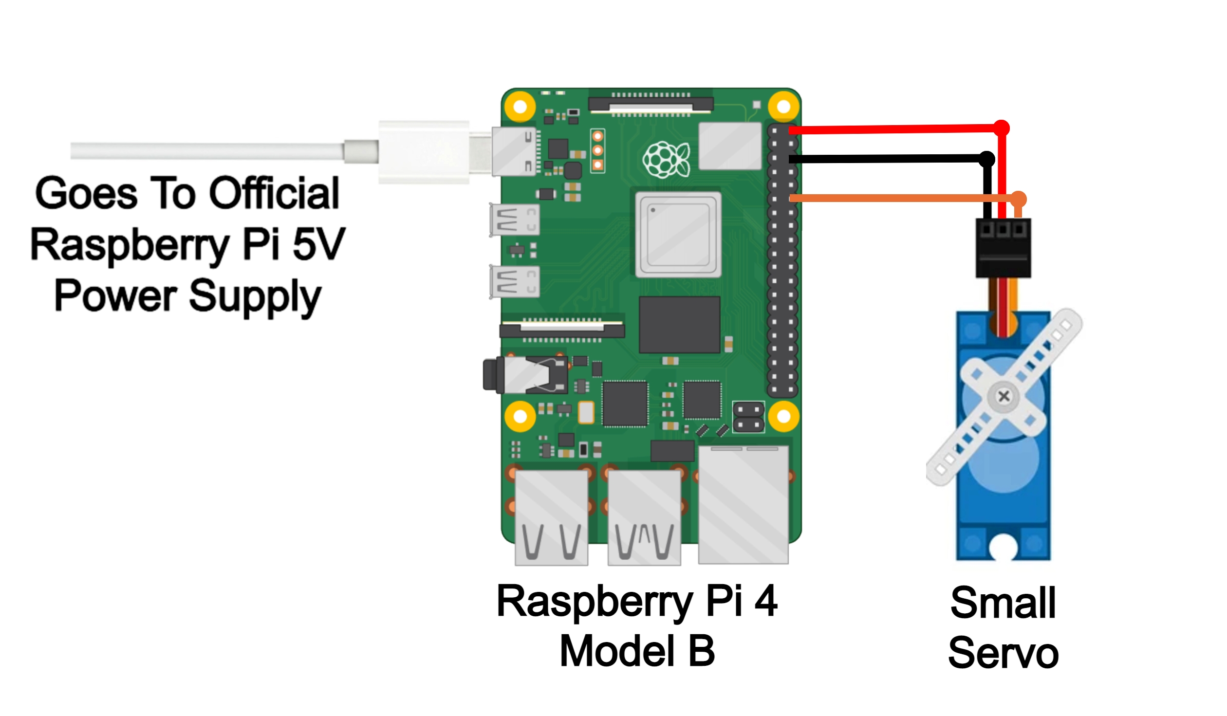
I will show you how to directly power a small servo and how to do it with a stronger power supply when dealing with a larger servo that has a high current demand. Below is the schematic to control a small servo without needing a more powerful power supply than the Official Raspberry Pi Power Supply. You can control at least two small servos using this similar method with no issues directly from a Raspberry Pi.
Connect to a ground pin of the Raspberry Pi to the ground wire on the Small Servo (dark brown/black wire most commonly seen as ground wires for small servos). Then connect the 5 Volt power (commonly red wire) to the 5 Volt pin on the Raspberry Pi. For this, I use the GPIO 18 (which is Pin Number 12) as the Data Pin telling the Small servo the direction and angle to turn to. The data wire on a Servo is usually an orange or white coloured wire. So once all of those are connected together using jumper cables it will look a lot like the image below.
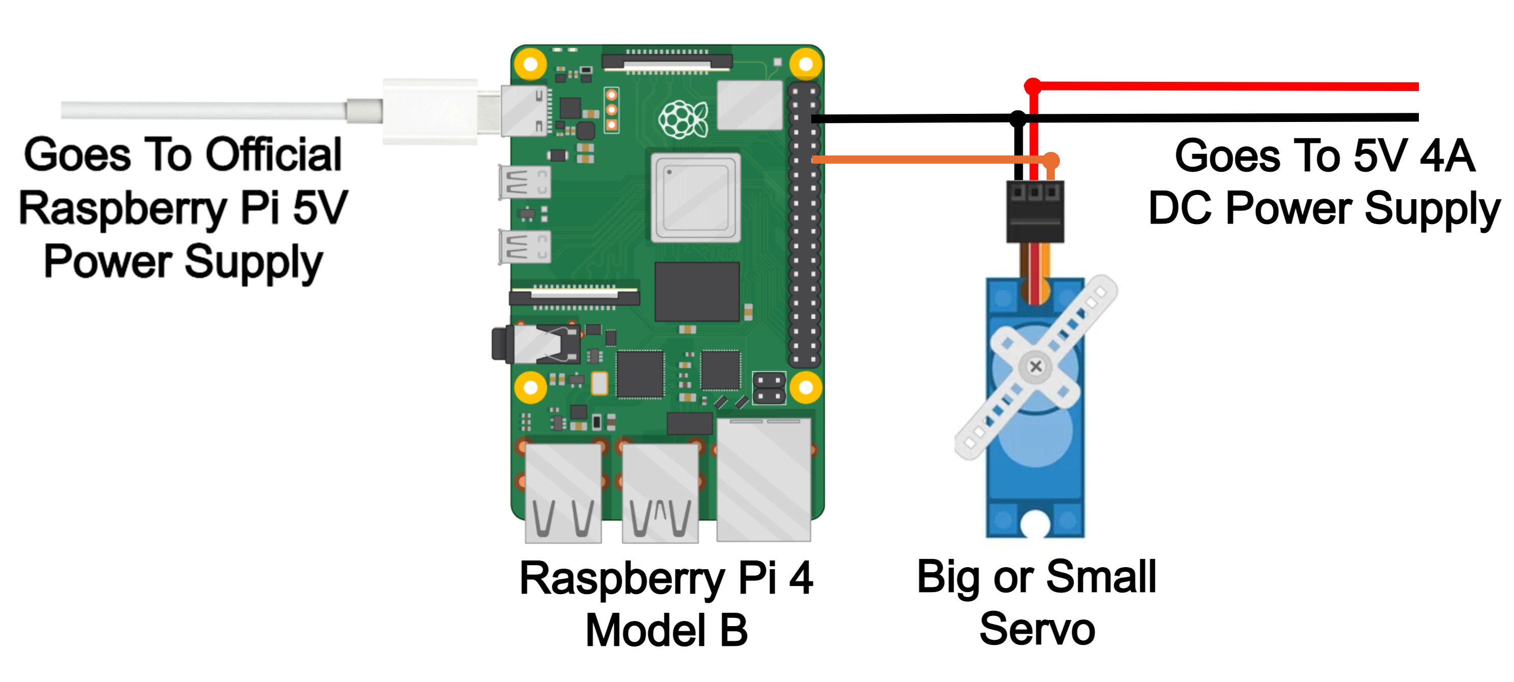
If, instead, you want to control a much more powerful servo likely the Raspberry Pi will not be able to provide enough current to the set-up. This also applies to multiple servos all running simultaneously. A single GPIO Pin can supply no more than 50 mA. Thus an external power supply will need to provide the current to run the servo. See the schematic below on how to do this.
Connect the ground pin of the Raspberry Pi to the ground wire on the small servo (dark brown/black wire most commonly seen as ground wire on big servos) by connecting the two wires to the DC Power Jack. This will attach the ground to the power supply as well. Then connect the power wire of the large servo (commonly red wire or dark brown) to the 5 volts of the external DC power supply. To send the data signal I use the GPIO 18 (which is pin number 12) as the Data Pin telling the servo the direction and angle to turn to. On a servo this is usually an orange or white coloured wire. Once all of those are connected together using jumper cables it will look a lot like the image below.
If you wanted to use only one Power plug you can incorporate a 2-way 2.1mm DC Barrel Jack Splitter and a DC to USB Type-C Adapter. Attach the barrel jack splitter to the DC Power Supply and have one end power the Raspberry Pi through the USB-C and the other side Power the Servo.
Code To Do It
There are a lot of ways you can get the Raspberry Pi to activate a servo. I will do the most intuitive way starting by connecting the Raspberry Pi up to a monitor with a mouse and keyboard and directly writing code to it. Check out this guide if you need help doing this. So with those peripheries connected plugin that USB C and wait until you see that familiar Raspberry Pi background. Open up a Python interface like Thonny. Click on the Application Menu (this is the Raspberry Pi Symbol on the top left of the screen and hover over the Programming Tab to find them). Then copy, paste and run the following code into the coding area (you can also download this code at the bottom of the page). Then if everything has turned out fine the code will make the servo move between its minimum, maximum, and mid-point positions with a pause between each.
The code below will work for the smaller servo.
from gpiozero import AngularServo
from time import sleep

servo = AngularServo(18, min_pulse_width=0.0006, max_pulse_width=0.0023)

while (True):
    servo.angle = 90
    sleep(2)
    servo.angle = 0
    sleep(2)
    servo.angle = -90
    sleep(2)
If you do not get full rotation out of your 180 Degree Servo adjust the min pulse width and max pulse width values by 0.0001 increments until you do.
Taking a look at the code. The Code is importing, from a library called gpiozero, a feature called AngularServo. This will make use GPIO pins on a Raspberry Pi very intuitive. Next line imports sleep. Then we create a variable called servo and give it details. We state that the data pin will be GPIO 18 and decide the min and max pulse width. Servo control here is done by sending the servo a PWM (pulse-width modulation) signal, a series of repeating pulses of variable width where the width of the pulse decides the angle of the servo arm. Each servo has unique specifications which you can find in the datasheet and often at the bottom of our product pages. There can be variation between the same type of servo thus feel free to adjust by 0.0001 increments. If you have full rotation and hear no gears straining you have found the best values. See below for the PWM specification highlighting the desired PWM value for the larger servo (we need these values in mm so divide those two numbers by 1000000 and you will have your min and max pulse width values, therefore it would be 0.0005 and 0.0025). Then the code sets up an endless loop using a while (True): statement and the servo goes from the min angle to the mid angle to the max angle with 2 seconds pause between each movement. The angle is decided by degrees.
So knowing that below is the code to do a similar process for the larger servo. This code when copy-pasted and run will move the servo from the min to mid and then max angle much like before. Where this code is different is in that this servo has an unusual higher angle range of movement (270 degrees). We adjust this in the line when we create a variable called servo and give it details using min_angle and max_angle. Then with these increased angles, the code in the endless loop is also adjusted.
The Code Below is for the larger servo.
from gpiozero import AngularServo
from time import sleep

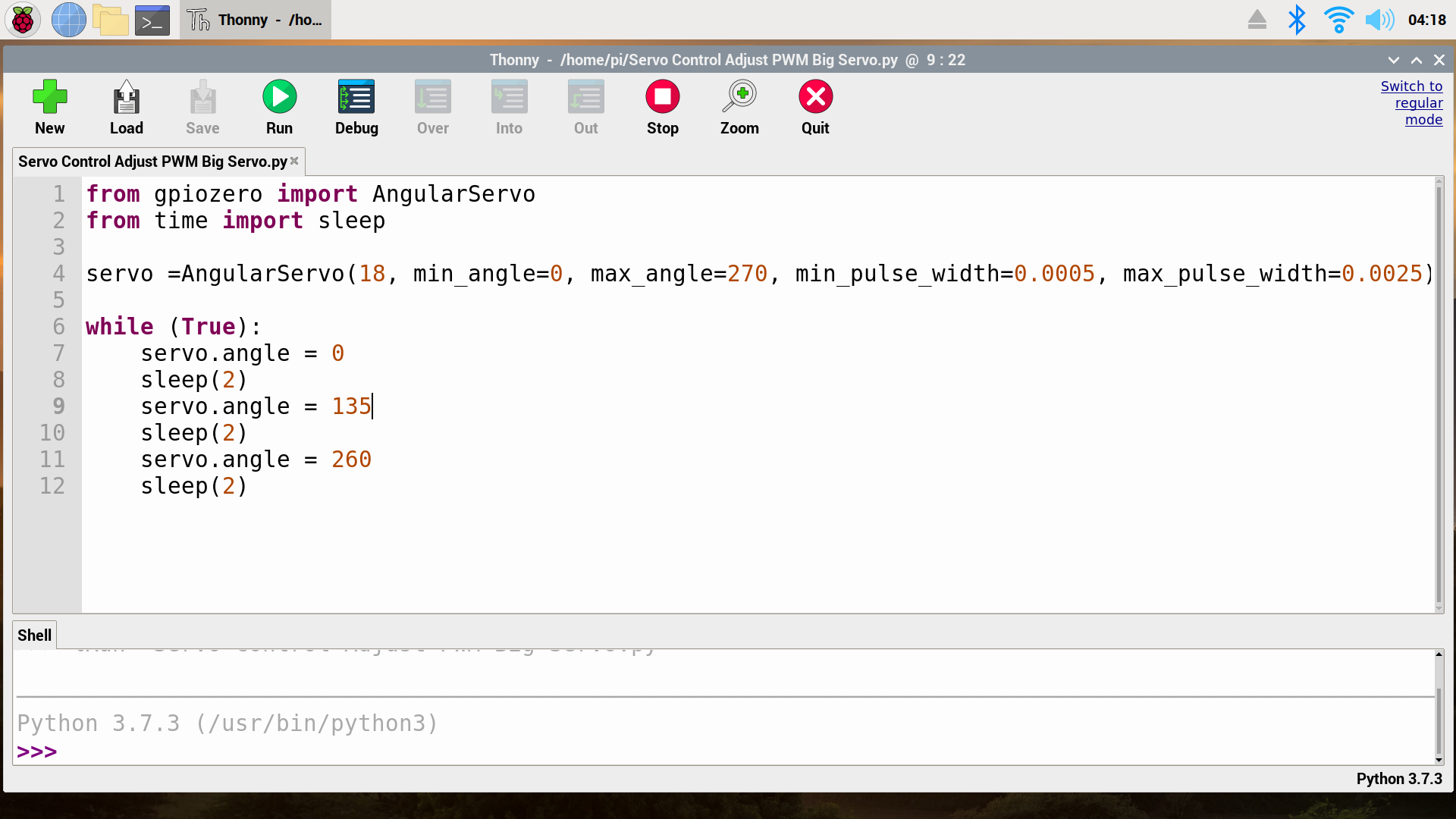
servo =AngularServo(18, min_angle=0, max_angle=270, min_pulse_width=0.0005, max_pulse_width=0.0025)

while (True):
    servo.angle = 0
    sleep(2)
    servo.angle = 135
    sleep(2)
    servo.angle = 260
    sleep(2)
Below is what this code will look like on your Raspberry Pi desktop
Download Code and Data Sheets for the Servos Utilised
Directly below you can download the Python code for the Raspberry Pi all ready to go to control your servo. For ideas on where to go next just check out this.

