


DRV8256E Single Brushed DC Motor Driver Carrier
Available with a lead time
Expect dispatch between Aug 03 and Aug 06
Quantity Discounts:
- 10+ $20.68 (exc GST)
- 25+ $20.04 (exc GST)
 |
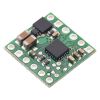
DRV8256E/P Single Brushed DC Motor Driver Carrier, bottom view with dimensions. |
|---|
Texas Instruments’ DRV8256E is a tiny H-bridge motor driver IC that can be used for bidirectional control of a single brushed DC motor at 4.5 V to 48 V. It can supply up to about 1.9 A continuously and can tolerate peak currents up to 6.4 A for a few seconds, making it a good choice for small motors that run on a wide range of voltages. Since this board is a carrier for the DRV8256E, Pololu recommend careful reading of the DRV8256 datasheet. The board ships populated with all of its SMD components, including the DRV8256E.
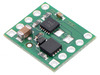
This DRV8256E uses a phase/enable interface that allows bidirectional control with only one PWM signal, but it is limited to drive/coast operation. The very similar DRV8256P has an IN/IN interface instead, requiring two PWM signals for full bidirectional control, but it offers drive/brake operation (which usually provides a more linear relationship between PWM duty cycle and motor speed). Pololu sell another version of this carrier board with the DRV8256P; the two versions can be distinguished by the markings on the driver chip.
The following table compares these drivers with the similar DRV8874 and DRV8876 drivers:
| Comparison of the DRV8874, DRV8876, and DRV8256 motor driver carriers | ||||
|---|---|---|---|---|
 DRV8876 (QFN) |  DRV8876 |  DRV8874 |  DRV8256E DRV8256P | |
| Motor channels: | one | |||
| Min. operating voltage: | 4.5 V | |||
| Max. operating voltage: | 37 V | 48 V | ||
| Max. continuous current(1): | 1.1 A | 1.3 A | 2.1 A | 1.9 A |
| Peak current: | 2 A(2) | 4.4 A(2) | 6.4 A | |
| Current sense feedback? | 2500 mV/A | 1100 mV/A | none | |
| Active current limiting: | adjustable | |||
| Size: | 0.6" × 0.7" | 0.6" × 0.6" | ||
| 1 On Pololu carrier board, at room temperature and without additional cooling. | ||||
| 2 Default current limit; see product descriptions for details. | ||||
Features
- Drives a single brushed DC motor
- Motor supply voltage: 4.5 V to 48 V
- Supports 1.8 V to 5 V logic voltage (5.5 V max)
- Output current: 1.9 A continuous (6.4 A peak)
- Simple interface requires only two I/O lines (one for direction and another for speed)
- Under-voltage lockout and protection against over-current and over-temperature
- Carrier board adds reverse-voltage protection up to 40 V
- Compact size (0.6"×0.6")
Using the motor driver
 |
Minimal wiring diagram for connecting a microcontroller to a DRV8256E Single Brushed DC Motor Driver Carrier. |
|---|
In a typical application, power connections are made on one side of the board and control connections are made on the other. Aside from motor and power connections (including a logic voltage connection to SLEEP), the only required control pins are ENABLE and PHASE.
| DRV8256E Truth Table | ||||
|---|---|---|---|---|
| ENABLE | PHASE | OUT1 | OUT2 | operating mode |
| PWM | 1 | PWM (H/OPEN) | L | forward/coast at speed PWM % |
| PWM | 0 | L | PWM (H/OPEN) | reverse/coast at speed PWM % |
| 0 | X | OPEN | OPEN | coast (outputs off) |
Pinout
 |
| PIN | Default State | Description |
|---|---|---|
| VIN | 4.5 V to 48 V board power supply input (reverse-protected up to 40 V). | |
| GND | Ground connection points for the motor and logic supplies. The control source and the motor driver must share a common ground. | |
| VM | This pin gives access to the motor power supply after the reverse-voltage protection MOSFET (see the board schematic below). It can be used to supply reverse-protected power to other components in the system. | |
| OUT1 | Motor output 1. | |
| OUT2 | Motor output 2. | |
| EN | LOW | Enable input for enabling the driver outputs/controlling motor speed. Logic high causes the motor to drive. A PWM signal can be applied to this pin. |
| PH | LOW | Phase input for controlling motor direction. |
| FAULT | FLOATING | Open-drain, active-low fault output. This pin goes low during an over-current, over-temperature, or under-voltage condition. You must use an external pull-up resistor to give this pin a default high value if you want to use it. |
| SLEEP | LOW | Sleep input that puts the DRV8256E into a low-power sleep mode when low. This pin can also be toggled to clear a latched over-current or over-temperature fault. |
| VREF | Current limiting threshold reference voltage (see below). |
Current limiting
The DRV8256 can actively limit the current through the motors by using a fixed off-time PWM current regulation (current chopping). The current limit is determined by the voltage on the VREF pin, which this carrier board pulls up to 5 V (DVDD) through a 47 kO resistor, setting the current limit to 6.4 A (the maximum possible). You can lower the current limit by connecting an additional resistor between VREF and GND or by connecting an external reference voltage directly to VREF. Refer to the DRV8256 datasheet for more information about the driver’s current regulation.
Real-world power dissipation considerations
The DRV8256 datasheet rates this driver for a peak current of 6.4 A, and that is its maximum possible current limiting threshold. However, the chip by itself will overheat at lower currents. In Pololu's tests, Pololu found that the chip was able to deliver 5 A for only a few seconds or 6.4 A for less than a second before the chip’s thermal protection kicked in and disabled the motor outputs; a continuous current of about 1.9 A was sustainable for many minutes without triggering a thermal shutdown.
The actual current you can deliver will depend on how well you can keep the motor driver cool. The carrier’s printed circuit board is designed to help with this by drawing heat out of the motor driver chip. PWMing the motor will introduce additional heating proportional to the frequency.
This product can get hot enough to burn you long before the chip overheats. Take care when handling this product and other components connected to it.
Included hardware
|
|


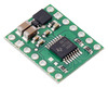
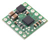
Breakaway 0.1" male headers are included with the DRV8256E motor driver carrier, which can be soldered in to use the driver with perfboards, breadboards, or 0.1" female connectors. (The headers might ship as a single larger strip that can be broken into smaller pieces.) When used with these header pins, the board can be oriented with the parts visible, as shown in the right picture above, or with the silkscreen visible, by soldering the headers in from the opposite side. You can also solder your motor leads and other connections directly to the board.
Schematic
 |
Schematic diagram for the DRV8256E/P Single Brushed DC Motor Driver Carrier. |
|---|
This diagram is also available as a downloadable pdf: DRV8256E/P Single Brushed DC Motor Driver Carrier schematic (119k pdf).
People often buy this product together with:
 | MAX14870 Single Brushed DC Motor Driver Carrier |
 | DRV8874 Single Brushed DC Motor Driver Carrier |
 | DRV8256P Single Brushed DC Motor Driver Carrier |
Dimensions
| Size: | 0.6" × 0.6" |
|---|---|
| Weight: | 0.6 g1 |
General specifications
| Motor driver: | DRV8256E |
|---|---|
| Motor channels: | 1 |
| Minimum operating voltage: | 4.5 V |
| Maximum operating voltage: | 48 V2 |
| Continuous output current per channel: | 1.9 A |
| Peak output current per channel: | 6.4 A |
| Maximum PWM frequency: | 100 kHz |
| Minimum logic voltage: | 1.8 V |
| Maximum logic voltage: | 5.5 V |
| Reverse voltage protection?: | Y3 |
| Header pins soldered?: | N |
Identifying markings
| PCB dev codes: | md42a |
|---|---|
| Other PCB markings: | 0J13491 |
Notes:
- 1
- Without included hardware.
- 2
- Not recommended for use with 48V batteries.
- 3
- Note: Reverse voltage protection only works up to 40 V.
File downloads
-
Schematic diagram of the DRV8256x Single Brushed DC Motor Driver Carrier (119k pdf)
-
Dimension diagram of the DRV8256x Single Brushed DC Motor Driver Carrier (290k pdf)
-
3D model of the DRV8256x Single Brushed DC Motor Driver Carrier (4MB step)
-
Drill guide for the DRV8256x Single Brushed DC Motor Driver Carrier (34k dxf)
Recommended links
Exact shipping can be calculated on the view cart page (no login required).
Products that weigh more than 0.5 KG may cost more than what's shown (for example, test equipment, machines, >500mL liquids, etc).
We deliver Australia-wide with these options (depends on the final destination - you can get a quote on the view cart page):
- $3+ for Stamped Mail (typically 10+ business days, not tracked, only available on selected small items)
- $7+ for Standard Post (typically 6+ business days, tracked)
- $11+ for Express Post (typically 2+ business days, tracked)
- Pickup - Free! Only available to customers who live in the Newcastle region (must order online and only pickup after we email to notify you the order is ready). Orders placed after 2PM may not be ready until the following business day.
Non-metro addresses in WA, NT, SA & TAS can take 2+ days in addition to the above information.
Some batteries (such as LiPo) can't be shipped by Air. During checkout, Express Post and International Methods will not be an option if you have that type of battery in your shopping cart.
International Orders - the following rates are for New Zealand and will vary for other countries:
- $12+ for Pack and Track (3+ days, tracked)
- $16+ for Express International (2-5 days, tracked)
If you order lots of gear, the postage amount will increase based on the weight of your order.
Our physical address (here's a PDF which includes other key business details):
40 Aruma Place
Cardiff
NSW, 2285
Australia
Take a look at our customer service page if you have other questions such as "do we do purchase orders" (yes!) or "are prices GST inclusive" (yes they are!). We're here to help - get in touch with us to talk shop.
Have a product question? We're here to help!
 Signal Diode (1N4148)SKU: CE05255 Brand: Core Electronics0.2A Forward Current, 1V Forward Voltage, Fast Switching Type.
- Voltage Regulator 5V (7805)SKU: CE05291 Brand: Core Electronics
An absolute staple! The ubiquitous L7805 voltage regulator, a three-terminal ...
- Low Profile Crystal Oscillator - 10 MhzSKU: CE05292 Brand: Core ElectronicsIdeal for precise MCU timing.
- Dual Digital Display DC Voltmeter & Ammeter 0-100V 0-100ASKU: CE05132 Brand: Core ElectronicsAn all in one solution for monitoring voltage and current.


- Adjustable Switching Power Supply Module IN 4V-35V OUT 1.5V-30V LM2596S Step-Down ConverterSKU: CE05572 Brand: Core ElectronicsA versatile power supply DC-DC converter module that offers a wide range for bot ...
- Stranded Wire: Black, 20 AWG, 40 FeetSKU: POLOLU-2650 Brand: PololuThis is a spool with 40 feet of black 20 AWG stranded copper hook-up wire. It co ...
- Stranded Wire: Yellow, 20 AWG, 40 FeetSKU: POLOLU-2654 Brand: PololuThis is a spool with 40 feet of yellow 20 AWG stranded copper hook-up wire. It c ...
- Stranded Wire: Blue, 20 AWG, 40 FeetSKU: POLOLU-2656 Brand: PololuThis is a spool with 40 feet of blue 20 AWG stranded copper hook-up wire. It con ...


Guides

The Maker Revolution
Projects

The Rats Nest VCC Desktop Power Supply

Remote-Controlled Mars Rover

FlipperMate: Hands-Free Pinball

Makers love reviews as much as you do, please follow this link to review the products you have purchased.
Product Comments