
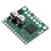


AMIS-30543 Stepper Motor Driver Carrier
Available with a lead time
Expect dispatch between Aug 03 and Aug 04
Quantity Discounts:
- 10+ $35.08 (exc GST)
- 25+ $33.99 (exc GST)
 |
AMIS-30543 stepper motor driver carrier, bottom view with dimensions. |
|---|
This product is a carrier board or breakout board for ON Semiconductor’s AMIS-30543 Micro-Stepping Motor Driver; Pololu therefore recommend careful reading of the AMIS-30543 datasheet (495k pdf) before using this product. This stepper motor driver lets you control one bipolar stepper motor at up to 3 A output current per coil (see the Power Dissipation Considerations section below for more information). Here are some of the board’s key features:
- Standard step and direction control interface
- SPI interface for configuring settings (e.g. step mode, current limit, sleep) and reading status registers
- Speed and load angle output that can be used for stall detection or closed-loop control of the torque and speed based on the load angle
- Eleven different step modes: full-step (uncompensated, compensated 1-phase, or compensated 2-phase), half-step (uncompensated or compensated), 1/4-step, 1/8-step, 1/16-step, 1/32-step, 1/64-step, and 1/128-step
- SPI-programmable current control (from 132 mA to 3 A) enables your microcontroller to adjust the peak-current limit on the fly as more or less torque or speed is needed
- Intelligent chopping control that automatically selects the correct current decay mode (fast decay or slow decay)
- Low-EMI PWM with SPI-selectable voltage slopes
- Compatible with 5 V and 3.3 V microcontrollers
- Integrated 5V regulator that can be used to supply an external microcontroller
- Integrated watchdog function
- Open coil detection
- Thermal warning indicates when the driver is close to the thermal shutdown temperature
- Over-current status and shutdown (short-to-ground and shorted-load protection)
- Reverse voltage protection
Note: This driver needs to be enabled and configured through its SPI interface on power up, so your microcontroller must be capable of acting as an SPI master (either with an SPI peripheral or software SPI).
 |
Included hardware
This product ships with all surface-mount components—including the AMIS-30543 driver IC—installed as shown in the product picture. However, soldering is required for assembly of the included through-hole parts. The following through-hole parts are included:
- One 1×20-pin breakaway 0.1" male header
- Three 2-pin, 3.5 mm terminal blocks (for board power and motor outputs)
- One 0.1" shorting block (for connecting IOREF to neighboring VDD pin)
The 0.1" male header can be broken or cut into smaller pieces as desired and soldered into the smaller through-holes. These headers are compatible with solderless breadboards, 0.1" female connectors, and Pololu's premium and pre-crimped jumper wires. The terminal blocks can be soldered into the larger holes to allow for convenient temporary connections of unterminated power and stepper motor wires. You can also solder your motor leads and other connections directly to the board for the most compact installation.
|
|


Using the driver
Pinout
 |
| PIN | Description |
|---|---|
| VMOT | Reverse-protected 6 V to 30 V board power supply connection. Note: Available VDD current is reduced for input voltages under 8 V, and sleep mode is not available for input voltages under 9 V. |
| VBB | This pin gives access to the motor power supply after the reverse-voltage protection MOSFET (see the board schematic below). It can be used to supply reverse-protected power to other components in the system. It is generally intended as an output, but it can also be used to supply board power. |
| GND | Ground connection points for the motor power supply and control ground reference. The control source and the motor driver must share a common ground. |
| MOTXP | Motor output: “positive” end of phase X coil. |
| MOTXN | Motor output: “negative” end of phase X coil. |
| MOTYP | Motor output: “positive” end of phase Y coil. |
| MOTYN | Motor output: “negative” end of phase Y coil. |
| VDD (5V OUT) | The board is powered by an internal 5V regulator, and this pin gives access to the regulated 5 V output. This can be used to supply the neighboring IOREF pin when using this board in 5V systems, and it can be used to power an external microcontroller. When VMOT is over 8 V, approximately 30 mA is available for external components; when VMOT is less than 8 V, the available current drops to less than 10 mA. |
| IOREF | All of the board signal outputs (except SLA) are open-drain outputs that are pulled up to IOREF, so this pin should be supplied with the logic voltage of the controlling system (e.g. 3.3V for use in 3.3V systems). For convenience, it can be connected to the neighboring VDD pin when it is being used in a 5V system. |
| NXT | Changes on this input move the motor current one step up or down in the translator table (even when the motor is disabled). The edge that triggers the step depends on the NXT-polarity configuration bit, which can be changed through the SPI interface (rising edge by default). |
| DIR | Input that determines the direction of rotation. The direction can also be controlled through the SPI interface. |
| DO | SPI data output. (This pin is also often referred to as “MISO”.) |
| DI | SPI data input. (This pin is also often referred to as “MOSI”.) |
| CLK | SPI clock input. |
| CS | SPI chip select input. Logic transitions on this pin are required for SPI communication, even if this is the only device on the SPI bus. |
| CLR | Chip reset input. A logic high on this input clears all internal registers, except in sleep mode. |
| ERR | Error output. This pin drives low to indicate that an error condition has occurred. The specific error can be determined by using the SPI interface to check the error flags. |
| POR/WD | Power-on reset/watch dog function output. This pin provides an active-low signal that can be used as a reset input for an external microcontroller. |
| SLA (filtered) | SLA (speed and load angle) output after a low-pass filter. The result is an analog voltage between 0 V and 5 V that indicates the level of the back-EMF voltage of the motor. This signal can be used for stall detection or closed-loop control of the torque and speed based on the load angle. Note: Since the output of this pin ranges from 0 V to 5 V regardless of IOREF, extra precautions should be taken when connecting this pin to a 3.3V device (such as passing it through an appropriate voltage divider). |
General minimal wiring diagram
 |
Minimal wiring diagram for connecting a microcontroller to an AMIS-30543 stepper motor driver carrier. |
|---|
While the AMIS-30543 allows control of a stepper motor through a simple step (NXT) and direction (DIR) interface, it first needs to be enabled and configured through its SPI interface. This means that the controlling microcontroller must be capable of acting as an SPI master (either with an SPI peripheral or software SPI), and it must be connected to the DI, CLK, and CS pins. While the DO and ERR pins are not required to use this driver, it is generally a good practice to use them to monitor for error conditions.
Minimal wiring diagram (5 V systems only)
 |
Minimal wiring diagram for connecting a microcontroller with a logic voltage of 5 V to an AMIS-30543 stepper motor driver carrier. |
|---|
The AMIS-30543 has an internal 5 V regulator that can be used to supply IOREF in cases where the board is being used in 5 V systems. This internal regulator can also be used to supply the external microcontroller’s logic voltage if the regulator can deliver the required current, in which case there would be a wire from the AMIS-30543 VDD to the microcontroller VDD in the above diagram, and the “logic power supply” box would not be present.
Arduino library and example code
 |
Controlling an AMIS-30543 stepper motor driver carrier with an Arduino-compatible #3104 A-Star 32U4 Mini SV. |
|---|
If you are new to the AMIS-30543 or stepper motors in general, Pololu's AMIS-30543 Arduino library can help you get started. The library provides basic functions for configuring and operating the driver using an Arduino or Arduino-compatible controller. It also provides access to many of the driver’s advanced features and includes example sketches that show you how to use them.
Power dissipation considerations
The AMIS-30543 driver IC has a maximum current rating of 3 A per coil, but the actual current you can deliver depends on how well you can keep the IC cool. The carrier’s printed circuit board is designed to draw heat out of the IC, but to supply more than approximately 1.8 A per coil continuously, a heat sink or other cooling method is required. However, it is possible to use the SPI-configurable current limit to selectively deliver higher currents than this for short durations without overheating the driver.
This product can get hot enough to burn you long before the chip overheats. Take care when handling this product and other components connected to it.
Please note that measuring the current draw at the power supply will generally not provide an accurate measure of the coil current. Since the input voltage to the driver can be significantly higher than the coil voltage, the measured current on the power supply can be quite a bit lower than the coil current (the driver and coil basically act like a switching step-down power supply). Also, if the supply voltage is very high compared to what the motor needs to achieve the set current, the duty cycle will be very low, which also leads to significant differences between average and RMS currents.
Schematic diagram
 |
AMIS-30543 stepper motor driver carrier schematic diagram. |
|---|
This diagram is also available as a downloadable pdf: AMIS-30543 stepper motor driver carrier schematic (231k pdf)
Dimensions
| Size: | 1.0" × 1.2" |
|---|---|
| Weight: | 4.0 g1 |
General specifications
| Minimum operating voltage: | 6 V2 |
|---|---|
| Maximum operating voltage: | 30 V |
| Continuous current per phase: | 1.8 A3 |
| Maximum current per phase: | 3 A4 |
| Minimum logic voltage: | 2.5 V |
| Maximum logic voltage: | 5.5 V |
| Microstep resolutions: | full, 1/2, 1/4, 1/8, 1/16, 1/32, 1/64, 1/128 |
| Reverse voltage protection?: | Y |
Identifying markings
| PCB dev codes: | md27a |
|---|---|
| Other PCB markings: | 0J8863 |
Notes:
- 1
- Without included optional headers or terminal blocks.
- 2
- The regulated 5V (VDD) output current is reduced for input voltages under 8 V, and sleep mode is not available for input voltages under 9 V.
- 3
- Without a heat sink or forced air flow.
- 4
- With sufficient additional cooling.
File downloads
-
ON Semiconductor AMIS-30543 stepper motor driver datasheet (495k pdf)
-
AMIS-30543 stepper motor driver carrier schematic diagram (231k pdf)
Printable schematic diagram of the AMIS-30543 Motor Driver Carrier.
-
Dimension diagram of the AMIS-30543 Stepper Motor Driver Carrier (437k pdf)
-
3D model of the AMIS-30543 Stepper Motor Driver Carrier (4MB step)
-
Drill guide for the AMIS-30543 Stepper Motor Driver Carrier (50k dxf)
This DXF drawing shows the locations of all of the board’s holes.
-
AMIS-30543 application note: how to measure Bemf on the SLA-pin (1MB PDF)
This application note from ON Semiconductor explains how to use the Speed and Load Angle (SLA) output to build accurate stall-detection and torque-adaptive algorithms.
Recommended links
-
AMIS-30543 library for Arduino
An Arduino library for controlling the AMIS-30543 micro-stepping stepper motor driver.
-
ON Semiconductor AMIS-30543 product page
ON Semiconductor product page for the AMIS-30543 microstepping stepper motor driver, where you can find the latest datasheet, application notes, and additional resources.
Exact shipping can be calculated on the view cart page (no login required).
Products that weigh more than 0.5 KG may cost more than what's shown (for example, test equipment, machines, >500mL liquids, etc).
We deliver Australia-wide with these options (depends on the final destination - you can get a quote on the view cart page):
- $3+ for Stamped Mail (typically 10+ business days, not tracked, only available on selected small items)
- $7+ for Standard Post (typically 6+ business days, tracked)
- $11+ for Express Post (typically 2+ business days, tracked)
- Pickup - Free! Only available to customers who live in the Newcastle region (must order online and only pickup after we email to notify you the order is ready). Orders placed after 2PM may not be ready until the following business day.
Non-metro addresses in WA, NT, SA & TAS can take 2+ days in addition to the above information.
Some batteries (such as LiPo) can't be shipped by Air. During checkout, Express Post and International Methods will not be an option if you have that type of battery in your shopping cart.
International Orders - the following rates are for New Zealand and will vary for other countries:
- $12+ for Pack and Track (3+ days, tracked)
- $16+ for Express International (2-5 days, tracked)
If you order lots of gear, the postage amount will increase based on the weight of your order.
Our physical address (here's a PDF which includes other key business details):
40 Aruma Place
Cardiff
NSW, 2285
Australia
Take a look at our customer service page if you have other questions such as "do we do purchase orders" (yes!) or "are prices GST inclusive" (yes they are!). We're here to help - get in touch with us to talk shop.
Have a product question? We're here to help!

-
- Horizontal Potentiometer 100 Pack (10 Types 100 to 1M Ohms)SKU: CE05106 Brand: Core ElectronicsThis pack includes many of the common types of Horizontal Potentiometers.
- DC-DC USB 0.9V-5V to 5V DC Boost Step-up Power Supply ModuleSKU: CE05174 Brand: Core ElectronicsConverts any DC voltage between 0.9V and 5V to a steady 5VDC. Can supply up to 6 ...


Guides

The Maker Revolution
Projects

The Rats Nest VCC Desktop Power Supply

Remote-Controlled Mars Rover

FlipperMate: Hands-Free Pinball

Makers love reviews as much as you do, please follow this link to review the products you have purchased.
Product Comments