Zumo Reflectance Sensor Array
In stock, ships same business day if ordered before 2PM
Fastest delivery: Tomorrow*
Disclaimer:
For next-day delivery, the shipping address must
be in the AusPost next-day network, eParcel Express must be selected, and the order must be placed
before 2PM AEST Mon-Thurs excluding NSW Public Holidays. Orders may be delayed due to AusPost
pickup timings and order verifications. eParcel Express is typically a 1-day service within the
AusPost next-day network, though it is sometimes 2+ days.
Quantity Discounts:
- 10+ $26.49 (exc GST)
- 25+ $25.66 (exc GST)
Note: This product is specifically designed to work with the Zumo shield for Arduino. For an alternative that works with Pololu's newer Zumo 32U4 robots, see the Zumo 32U4 Front Sensor Array.
 |
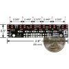
Zumo reflectance sensor array with labeled sensors and dimensions. |
|---|
Overview
The Zumo reflectance sensor array provides an easy way to add line sensing or edge detection to a Zumo robot. It features six separate reflectance sensors, each consisting of an IR emitter coupled with a phototransistor that responds based on how much emitter light is reflected back to it. The two outside sensors are positioned at the very edges of the module to maximize their usefulness as edge detectors (e.g. for seeing the white edge of a sumo ring) while the four inner sensors are closer together for better detecting lines. This sensor is included with the assembled version of the Zumo robot, but not with the kit version.
The sensor array plugs into the front expansion header of the Zumo shield, which provides it with power and the necessary I/O connections. The default I/O connections are to pins that are otherwise unused by the Zumo shield, but the sensor module makes it possible to remap these pins or disconnect specific sensors altogether to free up I/O lines. Please see the Zumo Shield user’s guide for detailed information about assembly and use with the Zumo robot.
|
|
Included components
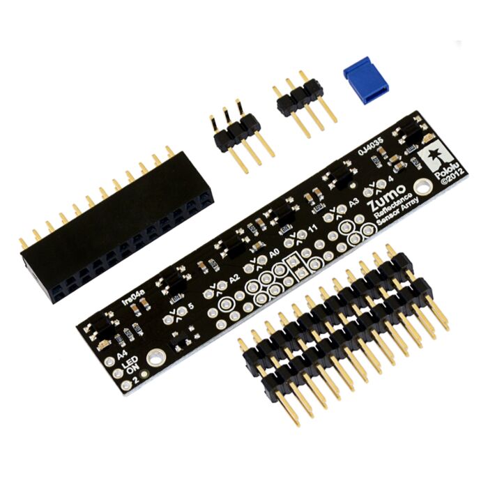
The Zumo reflectance sensor array ships with all of the components you need to connect it to a Zumo shield:
|
|
The short ends of the extended 2×12 male header strip should be soldered to the board as shown above (with the solder joints made on the component side of the array). The included 2×12 female header should be soldered to the front expansion area of the Zumo shield as described in the Zumo shield user’s guide. The array also ships with two 1×3 male headers: a straight version and a right-angle version. You can optionally solder the 1×3 header of your choice to the set of three holes along the edge of the board and use the included shorting block to connect the appropriate I/O line to the LEDON pin for dynamic control of the IR emitters (note: it is generally easier to install the 3-pin header before the larger 24-pin header). If you are content just having the IR emitters on all the time, you can skip installation of the 1×3 header. The assembled picture above shows the right-angle header installed.
How it works
 |
 |
QTR-1RC output (yellow) when 1/8" above a black line and microcontroller timing of that output (blue). |
|---|
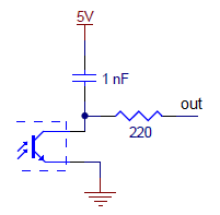
The array uses the same sensor modules as Pololu's QTR reflectance sensors and has the same principle of operation as Pololu's QTR-8RC version. The procedure for reading each sensor is as follows:
- Turn on IR LEDs (optional).
- Make the I/O line connected to that sensor an output and drive it high.
- Wait several microseconds to give the 1 nF capacitor node time to reach 5 V.
- Make the I/O line an input (with internal pull-up disabled).
- Measure the time for the voltage to decay by waiting for the I/O line to go low.
- Turn off IR LEDs (optional).
These steps can typically be executed in parallel for all six sensors. Pololu's Zumo Arduino library provides functions for reading the sensors and controlling the emitters (as well as high-level functions for taking calibrated readings and determining the position of a line), so you do not have to program this sequence of steps yourself.
With a strong reflectance, the decay time can be as low as several dozen microseconds; with no reflectance, the decay time can be up to a few milliseconds. Meaningful results can be available within 1 ms in typical cases (i.e. when not trying to measure subtle differences in low-reflectance scenarios), allowing up to 1 kHz sampling of all 6 sensors. If lower-frequency sampling is sufficient, substantial power savings can be realized by turning off the LEDs. For example, if a 100 Hz sampling rate is acceptable, the LEDs can be off 90% of the time, lowering average current consumption from 40 mA to 4 mA.
To minimize the required emitter current, the IR LEDs are arranged in two parallel chains of three and powered from the Zumo shield’s boosted 7.45 V. Each chain of emitters is wired in series with a red LED, making it possible to tell when current is flowing through that chain (it is not possible to tell if the IR LEDs are on by looking at them with the unaided eye). All of the IR emitter LEDs are controlled by a single MOSFET that is gated by a digital LEDON input that enables the emitters when left disconnected or driven high. If this input is driven low, the emitters are disabled. Turning the LEDs off might be advantageous for limiting power consumption when the sensors are not in use or for varying the effective brightness of the LEDs through PWM control. Additionally, reading the sensors with the emitters turned off makes it possible to detect (and potentially compensate for) any ambient IR that might be interfering with readings. When the emitters are on, the sensor array draws approximately 40 mA.
Schematic diagram
 |
This schematic diagram is also available as a downloadable pdf (211k pdf).
People often buy this product together with:
 | Basic Sumo Blade for Zumo Chassis |
 | 75:1 Micro Metal Gearmotor HP 6V |
 | Zumo Robot Kit for Arduino (No Motors) |
Dimensions
| Size: | 2.6" × 0.6"1 |
|---|---|
| Weight: | 3.6 g2 |
General specifications
| Supply current: | 40 mA |
|---|
Notes:
- 1
- Without header pins.
- 2
- Without included hardware. Weight becomes 8.1 g with included male and female headers.
Documentation and other information
-
Pololu Zumo Shield for Arduino User’s Guide (Printable PDF)
User’s manual for the Pololu Zumo Shield for Arduino.
File downloads
-
Zumo reflectance sensor array schematic diagram (211k pdf)
Printable schematic diagram for the Pololu Zumo reflectance sensor array.
-
Dimension diagram of the Zumo Reflectance Sensor Array (121k pdf)
Exact shipping can be calculated on the view cart page (no login required).
Products that weigh more than 0.5 KG may cost more than what's shown (for example, test equipment, machines, >500mL liquids, etc).
We deliver Australia-wide with these options (depends on the final destination - you can get a quote on the view cart page):
- $3+ for Stamped Mail (typically 10+ business days, not tracked, only available on selected small items)
- $7+ for Standard Post (typically 6+ business days, tracked)
- $11+ for Express Post (typically 2+ business days, tracked)
- Pickup - Free! Only available to customers who live in the Newcastle region (must order online and only pickup after we email to notify you the order is ready). Orders placed after 2PM may not be ready until the following business day.
Non-metro addresses in WA, NT, SA & TAS can take 2+ days in addition to the above information.
Some batteries (such as LiPo) can't be shipped by Air. During checkout, Express Post and International Methods will not be an option if you have that type of battery in your shopping cart.
International Orders - the following rates are for New Zealand and will vary for other countries:
- $12+ for Pack and Track (3+ days, tracked)
- $16+ for Express International (2-5 days, tracked)
If you order lots of gear, the postage amount will increase based on the weight of your order.
Our physical address (here's a PDF which includes other key business details):
40 Aruma Place
Cardiff
NSW, 2285
Australia
Take a look at our customer service page if you have other questions such as "do we do purchase orders" (yes!) or "are prices GST inclusive" (yes they are!). We're here to help - get in touch with us to talk shop.
Have a product question? We're here to help!
Videos
View AllGuides
The Maker Revolution
Getting Hands-on with Sensors
Projects
WhyzaGC - Feather ESP32 addon to the MightyOhm Gieger Counter
Makers love reviews as much as you do, please follow this link to review the products you have purchased.





Product Comments