


TB67S581FNG Stepper Motor Driver Carrier
Available with a lead time
Expect dispatch between Aug 07 and Aug 10
Quantity Discounts:
- 10+ $10.21 (exc GST)
- 25+ $9.89 (exc GST)
 |
This product is a carrier board or breakout board for Toshiba’s TB67S581FNG stepper motor driver; Pololu therefore recommend careful reading of the TB67S581FNG datasheet (1MB pdf) before using this product. This stepper motor driver lets you control one bipolar stepper motor at up to 2.2 A output current per coil (see the Power Dissipation Considerations section below for more information). Here are some of the driver’s key features:
- Simple step and direction control interface
- Six different step resolutions: full-step, half-step, 1/4-step, 1/8-step, 1/16-step, and 1/32-step
- Adjustable current control lets you set the maximum current output with a potentiometer, which lets you use voltages above your stepper motor’s rated voltage to achieve higher step rates
- Configured for mixed decay mode
- 44 V maximum supply voltage
- Built-in regulator (no external logic voltage supply needed)
- Can interface directly with 3.3 V and 5 V systems
- Over-temperature thermal shutdown, over-current shutdown, and under-voltage lockout
- Short-to-ground and shorted-load protection
- 4-layer, 2 oz copper PCB for improved heat dissipation
- Exposed solderable ground pad below the driver IC on the bottom of the PCB
- Module size, pinout, and interface match those of Pololu's DRV8825 and A4988 stepper motor driver carriers in most respects (see the bottom of this page for more information)
Pololu also have a variety of other stepper motor driver options in this same form factor with different operating profiles and features.
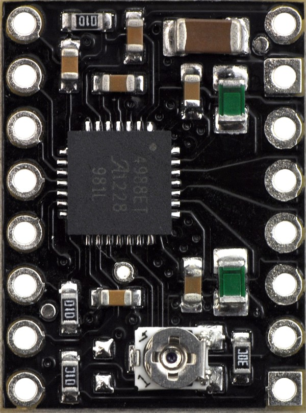
This product ships with all surface-mount components—including the TB67S581FNG driver IC—installed as shown in the product picture.
This version does not have header pins soldered or included; 0.1" headers are available separately, as is a version of this driver with header pins already soldered.
|
|
|


Caution: Installing the header pins so that the silkscreen side is up and the components are down can limit the range of motion of the trimpot used to set the current limit. If you plan on installing the header pins in this orientation, please set the current limit before soldering in the pins.
Using the driver
Pinout
 |
Pinout of the TB67S581FNG Stepper Motor Driver Carrier with silkscreen labels in bold and corresponding TB67S581FNG pin names in parentheses. |
|---|
Minimal wiring diagram
 |
Minimal wiring diagram for connecting a microcontroller to TB67S581FNG Stepper Motor Driver Carrier (full-step mode). |
|---|
Power connections
The driver requires a motor supply voltage of 8.2 – 44 V to be connected across VMOT and GND. This supply should have appropriate decoupling capacitors close to the board, and it should be capable of delivering the expected stepper motor current.
Warning: This carrier board uses low-ESR ceramic capacitors, which makes it susceptible to destructive LC voltage spikes, especially when using power leads longer than a few inches. Under the right conditions, these spikes can exceed the 44 V maximum voltage rating for the TB67S581FNG and permanently damage the board, even when the motor supply voltage is as low as 12 V. One way to protect the driver from such spikes is to put a large (at least 47 µF) electrolytic capacitor across motor power (VMOT) and ground somewhere close to the board.
Motor connections
Four, six, and eight-wire stepper motors can be driven by the TB67S581FNG if they are properly connected; a FAQ answer explains the proper wirings in detail.
Warning: Connecting or disconnecting a stepper motor while the driver is powered can destroy the driver. (More generally, rewiring anything while it is powered is asking for trouble.)
Step (and microstep) size
Stepper motors typically have a step size specification (e.g. 1.8° or 200 steps per revolution), which applies to full steps. A microstepping driver such as the TB67S581FNG allows higher resolutions by allowing intermediate step locations, which are achieved by energizing the coils with intermediate current levels. For instance, driving a motor in quarter-step mode will give the 200-step-per-revolution motor 800 microsteps per revolution by using four different current levels.
The resolution (step size) selector inputs—DMODE0, DMODE1, and DMODE2—enable selection from the six step resolutions according to the table below. All three selector inputs have internal 100 kO pull-down resistors, so leaving these three microstep selection pins disconnected results in full-step mode. For the microstep modes to function correctly, the current limit must be set low enough (see below) so that current limiting gets engaged. Otherwise, the intermediate current levels will not be correctly maintained, and the motor will skip microsteps.
| M2 (DMODE2) | M1 (DMODE1) | M0 (DMODE0) | Microstep Resolution |
|---|---|---|---|
| Low | Low | Low | Full step |
| Low | Low | High | Half step |
| Low | High | Low | 1/4 step |
| Low | High | High | 1/8 step |
| High | Low | Low | 1/16 step |
| High | Low | High | 1/32 step |
| High | High | Low | |
| High | High | High |
Control inputs
Each pulse to the STEP (CLK) input corresponds to one microstep of the stepper motor in the direction selected by the DIR (CW/CCW) pin. These inputs are both pulled low by default through internal 100kO pull-down resistors. If you just want rotation in a single direction, you can leave DIR disconnected.
The chip has three different inputs for controlling its power states: RST (RESET_X), SLP (SLEEP_X), and EN (ENABLE_X). For details about these power states, see the datasheet. Please note that the driver pulls the SLP pin low through an internal pull-down resistor (the datasheet does not specify the value of this pull-down, but in Pololu's tests, Pololu measured it to be around 100 kO), and it pulls the RST and EN pins low through internal 100 kO; pull-down resistors. These default RST and SLP states are ones that prevent the driver from operating; both of these pins must be high to enable the driver (they can be connected directly to a logic “high” voltage between 2.5 and 5.25 V, or they can be dynamically controlled via connections to digital outputs of an MCU). The default state of the EN pin is to enable the driver, so this pin can be left disconnected.
 |
Schematic of SLP (SLEEP_X) and FLT (LO) pins on the TB67S581FNG carrier. |
|---|
The TB67S581FNG also features a FLT (LO) output that drives low whenever the H-bridge FETs are disabled as the result of over-current protection or thermal shutdown. The carrier board connects this pin to the SLP pin through a 10 kO resistor that acts as a FLT pull-up whenever SLP is externally held high, so no external pull-up is necessary on the FLT pin. Note that the carrier includes a 1.5 kO protection resistor in series with the FLT pin that makes it safe to connect this pin directly to a logic voltage supply, as might happen if you use this board in a system designed for the pin-compatible A4988 carrier. In such a system, the 10 kO resistor between SLP and FLT would then act as a pull-up for SLP, making the TB67S581FNG carrier more of a direct replacement for the A4988 in such systems (the A4988 has an internal pull-up on its SLP pin). To keep faults from pulling down the SLP pin, any external pull-up resistor you add to the SLP pin input should not exceed 4.7 kO.
Current limiting
To achieve high step rates, the motor supply is typically much higher than would be permissible without active current limiting. For instance, a typical stepper motor might have a maximum current rating of 1 A with a 5O coil resistance, which would indicate a maximum motor supply of 5 V. Using such a motor with 12 V would allow higher step rates, but the current must actively be limited to under 1 A to prevent damage to the motor.
The TB67S581FNG supports such active current limiting, and the trimmer potentiometer on the board can be used to set the current limit. You will typically want to set the driver’s current limit to be at or below the current rating of your stepper motor. One way to set the current limit is to put the driver into full-step mode and to measure the current running through a single motor coil without clocking the STEP input. The measured current will be 0.7 times the current limit (since both coils are always on and limited to approximately 70% of the current limit setting in full-step mode).
Another way to set the current limit is to measure the voltage on the “ref” pin and to calculate the resulting current limit (the current sense resistors are 0.100O). The ref pin voltage is accessible on a via that is circled on the bottom silkscreen of the circuit board. The current limit in amps relates to the reference voltage in volts as follows:
or, rearranged to solve for VREF:
So, for example, if you have a stepper motor rated for 1 A, you can set the current limit to 1 A by setting the reference voltage to 0.5 V.
Note: The coil current can be very different from the power supply current, so you should not use the current measured at the power supply to set the current limit. The appropriate place to put your current meter is in series with one of your stepper motor coils.
Power dissipation considerations
The TB67S581FNG driver IC has a maximum current rating of 2.5 A per coil, but the current sense resistors further limit the maximum current to 2.2 A, and the actual current you can deliver depends on how well you can keep the IC cool. The carrier’s printed circuit board is designed to draw heat out of the IC, but to supply more than approximately 1.5 A per coil, a heat sink or other cooling method is required.
This product can get hot enough to burn you long before the chip overheats. Take care when handling this product and other components connected to it.
Please note that measuring the current draw at the power supply will generally not provide an accurate measure of the coil current. Since the input voltage to the driver can be significantly higher than the coil voltage, the measured current on the power supply can be quite a bit lower than the coil current (the driver and coil basically act like a switching step-down power supply). Also, if the supply voltage is very high compared to what the motor needs to achieve the set current, the duty cycle will be very low, which also leads to significant differences between average and RMS currents. Additionally, please note that the coil current is a function of the set current limit, but it does not necessarily equal the current limit setting. The actual current through each coil changes with each microstep. See the TB67S581FNG datasheet for more information.
Schematic diagram
 |
Schematic diagram for the TB67S581FNG stepper motor driver carrier. |
|---|
The current sense resistors (R2 and R3) on the TB67S581FNG carrier are 0.100 O.
Key differences between the TB67S581FNG, DRV8825, and A4988
The TB67S581FNG is Toshiba’s version of the TI DRV8825, so it is pin compatible and functionally equivalent to the DRV8825, and Pololu use the same PCB for both carriers. As such, Pololu expect the TB67S581FNG carrier and the DRV8825 carrier to be usable interchangeably.
This carrier can also be used as drop in replacement for the A4988 stepper motor driver carrier in many applications because it shares the same size, pinout, and general control interface. There are a few differences between the two modules that should be noted, however:
 |
TB67S581FNG Stepper Motor Driver Carrier, top view. |
|---|
 |
A4988 stepper motor driver carrier, Black Edition (shown with original green 50 mO current sense resistors). |
|---|
- The pin used to supply logic voltage to the A4988 is used as the TB67S581FNG’s FLT output, since the TB67S581FNG does not require a logic supply (and the A4988 does not have a fault output). Note that it is safe to connect the FLT pin directly to a logic supply (there is a 1.5 kO resistor between the IC output and the pin to protect it), so the TB67S581FNG module can be used in systems designed for the A4988 that route logic power to this pin.
- The SLP pin on the TB67S581FNG is not pulled up by default like it is on the A4988, but the carrier board does connect it to the FLT pin through a 10 kO resistor. Therefore, systems intended for the A4988 that route logic power to the FLT pin will effectively have a 10 kO pull-up on the SLP pin.
- The current limit potentiometer is in a different location.
- The relationship between the current limit setting and the reference pin voltage is different.
- The TB67S581FNG offers 1/32-step microstepping; the A4988 only goes down to 1/16-step.
- The mode selection pin inputs corresponding to 1/16-step on the A4988 result in 1/32-step microstepping on the TB67S581FNG. For all other microstepping resolutions, the step selection table is the same for both the TB67S581FNG and the A4988.
- The timing requirements for minimum pulse durations on the STEP pin are different for the two drivers. With the TB67S581FNG, the high and low STEP pulses must each be at least 1.9 us; they can be as short as 1 us when using the A4988.
- The TB67S581FNG has a higher maximum supply voltage than the A4988 (44 V vs 35 V), which means the TB67S581FNG can be used more safely at higher voltages and is less susceptible to damage from LC voltage spikes.
- The TB67S581FNG can deliver more current than the A4988 without any additional cooling (based on Pololu's full-step tests: 1.5 A per coil for the TB67S581FNG vs 1.2 A per coil for the A4988 Black Edition and 1 A per coil for the original A4988 carrier).
- The TB67S581FNG uses a different naming convention for the stepper motor outputs, but they are functionally the same as the corresponding pins on the A4988 carrier, so the same connections to both drivers result in the same stepper motor behavior. On both boards, the first part of the label identifies the coil (so you have coils “A” and “B” on the TB67S581FNG and coils “1” and “2” on the A4988).
- For those with color-sensitive applications, note that the TB67S581FNG carrier is purple.
In summary, the TB67S581FNG carrier is similar enough to Pololu's A4988 carriers that the minimum connection diagram for the A4988 is a valid alternate way to connect the TB67S581FNG to a microcontroller as well:
 |
Alternative minimal wiring diagram for connecting a microcontroller to a TB67S581FNG Stepper Motor Driver Carrier (full-step mode). |
|---|
Dimensions
| Size: | 0.6" × 0.8" |
|---|---|
| Weight: | 1.6 g |
General specifications
| Minimum operating voltage: | 8.2 V |
|---|---|
| Maximum operating voltage: | 44 V |
| Continuous current per phase: | 1.5 A1 |
| Maximum current per phase: | 2.2 A2 |
| Minimum logic voltage: | 2.5 V3 |
| Maximum logic voltage: | 5.25 V3 |
| Microstep resolutions: | full, 1/2, 1/4, 1/8, 1/16, and 1/32 |
| Reverse voltage protection?: | N |
| Header pins: | not included |
Identifying markings
| PCB dev codes: | md20b |
|---|---|
| Other PCB markings: | blank white box |
Notes:
- 1
- Without a heat sink or forced air flow.
- 2
- With sufficient additional cooling.
- 3
- This driver works with 2.5 V to 5.25 V logic. It does not take an external logic power supply.
File downloads
-
TB67S581FNG datahseet (1MB pdf)
-
Dimension diagram of the TB67S581FNG Stepper Motor Driver Carrier (327k pdf)
-
3D model of the TB67S581FNG Stepper Motor Driver Carrier (6MB step)
-
Drill guide for the TB67S581FNG Stepper Motor Driver Carrier (19k dxf)
This DXF drawing shows the locations of all of the board’s holes.
Recommended links
-
Video: setting the current limit on Pololu stepper motor driver carriers
-
Arduino library for A4988, DRV8825, DRV8834, DRV8880, and TB67S581FNG
This Arduino library, written by forum member laurb9, allows users to control a stepper motor with Pololu's A4988, DRV8825, DRV8834, and TB67S581FNG"-based carriers (for the TB67S581FNG, use the library code for the DRV8825 as the TB67S581FNG is Toshiba’s version of the DRV8825). The library has functions that enable users to set rotational rate, change microstepping mode, and specify how many steps to take or specify how many degrees to rotate.
Exact shipping can be calculated on the view cart page (no login required).
Products that weigh more than 0.5 KG may cost more than what's shown (for example, test equipment, machines, >500mL liquids, etc).
We deliver Australia-wide with these options (depends on the final destination - you can get a quote on the view cart page):
- $3+ for Stamped Mail (typically 10+ business days, not tracked, only available on selected small items)
- $7+ for Standard Post (typically 6+ business days, tracked)
- $11+ for Express Post (typically 2+ business days, tracked)
- Pickup - Free! Only available to customers who live in the Newcastle region (must order online and only pickup after we email to notify you the order is ready). Orders placed after 2PM may not be ready until the following business day.
Non-metro addresses in WA, NT, SA & TAS can take 2+ days in addition to the above information.
Some batteries (such as LiPo) can't be shipped by Air. During checkout, Express Post and International Methods will not be an option if you have that type of battery in your shopping cart.
International Orders - the following rates are for New Zealand and will vary for other countries:
- $12+ for Pack and Track (3+ days, tracked)
- $16+ for Express International (2-5 days, tracked)
If you order lots of gear, the postage amount will increase based on the weight of your order.
Our physical address (here's a PDF which includes other key business details):
40 Aruma Place
Cardiff
NSW, 2285
Australia
Take a look at our customer service page if you have other questions such as "do we do purchase orders" (yes!) or "are prices GST inclusive" (yes they are!). We're here to help - get in touch with us to talk shop.
Have a product question? We're here to help!
 General Purpose Diode 1N4007SKU: CE05261 Brand: Core Electronics1A Forward Current, 1.1V Forward Voltage Drop.
-
- Arduino Uno R3SKU: A000066 Brand: ArduinoThe Arduino UNO is the most used board in the family of Arduino boards. If you ...
- Digital Display DC Voltmeter 0-100V BlueSKU: CE06395 Brand: Core ElectronicsWide supply voltage range and measuring range. 3 wire interface that can be conf ...


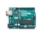

- Arduino Uno R3SKU: A000066 Brand: ArduinoThe Arduino UNO is the most used board in the family of Arduino boards. If you ...
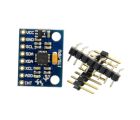
- MPU-6050 Module 3 Axis Gyroscope + AccelerometerSKU: 018-MPU-6050 Brand: Core ElectronicsA 3-axis gyroscope and 3-axis accelerometer housed on a development board ready ...
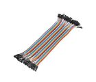
- Jumper Wire 20cm Ribbon (F/F, 40pcs)SKU: CE05098 Brand: Core ElectronicsJumpstart your electronics project with a pack of 40, 20cm female-to-female jump ...
- 40 Pin Break Away Male Header- Long Straight-10 PcsSKU: FIT0105 Brand: DFRobotThese are a longer version of our standard break away headers. They are 10mm lon ...

Videos
View AllGuides

The Maker Revolution

Motor Drivers vs. Motor Controllers
Projects

3D Printed Pico Weather Display

Makers love reviews as much as you do, please follow this link to review the products you have purchased.
Product Comments