

TB67S279FTG Stepper Motor Driver Compact Carrier
In stock, ships same business day if ordered before 2PM
Delivered by Tue, 21st of Jul
Quantity Discounts:
- 10+ $17.24 (exc GST)
- 25+ $16.70 (exc GST)
 |
TB67S2x9FTG Stepper Motor Driver Compact Carrier, bottom view with dimensions. |
|---|
This product is a carrier board or breakout board for Toshiba’s TB67S2x9FTG family of stepper motor drivers; Pololu therefore recommend careful reading of the corresponding driver’s datasheet before using this product. This stepper motor driver lets you control one bipolar stepper motor and is available in two different versions: the TB67S249FTG can deliver about 1.6 A per phase continuously (4.5 A peak), and the TB67S279FTG can deliver about 1.1 A per phase continuously (2 A peak). (See the Power Dissipation Considerations section below for more information.)
Pololu also carry larger, complete breakout versions of the TB67S249FTG and TB67S279FTG stepper driver carriers that bring out all the pins from the driver, allowing access to all of the drivers’ features.
Here are some of the board’s key features:- Simple step and direction control interface
- Seven different step modes: full-step, non-circular half-step, circular half-step, 1/4-step, 1/8-step, 1/16-step, and 1/32-step
- Adjustable current control lets you set the maximum current output with a potentiometer, which lets you use voltages above your stepper motor’s rated voltage to achieve higher step rates
- Advanced Dynamic Mixed Decay (ADMD) dynamically switches between slow and fast decay modes by monitoring the state of current decay (not according to fixed timing)
- Configurable Active Gain Control (AGC) can be enabled to automatically reduce drive current by up to 40% to minimize power consumption and heat generation when maximum torque is not needed.
- Motor supply voltage: 10 V to 47 V
- Maximum continuous current per phase without additional cooling:
- TB67S249FTG: 1.6 A (4.5 A peak)
- TB67S279FTG: 1.1 A (2 A peak)
- Built-in regulator (no external logic voltage supply needed)
- Can interface directly with 3.3 V and 5 V systems
- Under-voltage lockout and protection against over-current/short-circuit and over-temperature
- Open-load detection
- Active-low error outputs indicate over-current, over-temperature, or open-load condition
- Compact size (0.6" × 0.8")
- 4-layer, 2 oz copper PCB for improved heat dissipation
- Exposed solderable ground pad below the driver IC on the bottom of the PCB
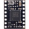
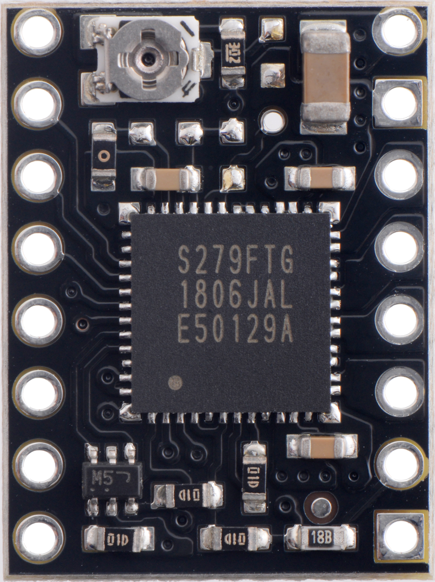
This product ships with all surface-mount components—including the TB67S2x9FTG driver IC—installed as shown in the product picture.
Some unipolar stepper motors (e.g. those with six or eight leads) can be controlled by this driver as bipolar stepper motors. For more information, please see the frequently asked questions. Unipolar motors with five leads cannot be used with this driver.
Details for item #3098
This compact version uses a TB67S279FTG driver and can deliver approximately 1.1 A per phase continuously without a heat sink or forced air flow (up to 2 A peak). It can be distinguished by the marking “S279FTG” on the driver IC.
For more information about this driver, please read the TB67S279FTG datasheet (536k pdf).
 |
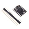
Header pins are included but not soldered (see item #3099 for a version of this carrier with header pins already installed).
Included hardware
The TB67S2x9FTG stepper motor driver compact carrier ships with one 1×16-pin breakaway 0.1" male headers. The headers can be soldered in for use with solderless breadboards or 0.1" female connectors. You can also solder your motor leads and other connections directly to the board.
|
|


Using the driver
 |
Minimal wiring diagram for connecting a microcontroller to a TB67S2x9FTG stepper motor driver compact carrier. |
|---|
Power connections
The driver requires a motor supply voltage of 10 V to 47 V to be connected across VIN and GND. This supply should be capable of delivering the expected stepper motor current.
Motor connections
Four, six, and eight-wire stepper motors can be driven by the TB67S2x9FTG if they are properly connected; a FAQ answer explains the proper wirings in detail.
Warning: Connecting or disconnecting a stepper motor while the driver is powered can destroy the driver. (More generally, rewiring anything while it is powered is asking for trouble.)
Step (and microstep) size
Stepper motors typically have a step size specification (e.g. 1.8° or 200 steps per revolution), which applies to full steps. A microstepping driver such as the TB67S2x9FTG allows higher resolutions by allowing intermediate step locations, which are achieved by energizing the coils with intermediate current levels. For instance, driving a motor in quarter-step mode will give the 200-step-per-revolution motor 800 microsteps per revolution by using four different current levels.
The resolution (step size) selector inputs (DMODE0, DMODE1, and DMODE2) enable selection from the seven step resolutions according to the table below. These three pins have internal 100 kO pull-down resistors, so the driver defaults to standby mode when these inputs are left disconnected; at least one DMODE pin must be driven high to select a step resolution and allow the driver to operate. For the microstep modes to function correctly, the current limit must be set low enough (see below) so that current limiting gets engaged. Otherwise, the intermediate current levels will not be correctly maintained, and the motor will skip microsteps.
| DMODE0 | DMODE1 | DMODE2 | Microstep Resolution |
|---|---|---|---|
| Low | Low | Low | Standby mode (outputs disabled) |
| Low | Low | High | Full step |
| Low | High | Low | Non-circular half step (“a”) |
| Low | High | High | 1/4 step |
| High | Low | Low | Circular half step (“b”) |
| High | Low | High | 1/8 step |
| High | High | Low | 1/16 step |
| High | High | High | 1/32 step |
Control inputs and status outputs
The rising edge of each pulse to the STEP (CLK) input corresponds to one microstep of the stepper motor in the direction selected by the DIR (CW/CCW) pin. These inputs are both pulled low by default through internal 100 kO pull-down resistors. If you just want rotation in a single direction, you can leave CW/CCW disconnected.
Pololu's compact breakout board inverts the inputs for ENABLE and RESET to match the pinout of Pololu's popular A4988 carriers to make it a suitable drop-in replacement. By default, ENABLE is pulled low with a 100 kO resistor and RESET is pulled high with a 100 kO resistor. You can disable the board by driving ENABLE high (it can be connected directly to a logic high voltage between 2 V and 5.5 V, such as the driver’s own VCC output, or it can be dynamically controlled via connections to digital outputs of an MCU).
When the RESET pin is driven low, the driver resets its internal electrical angle (the state in the translator table that it is outputting) to an initial value of 45°. This corresponds to +100% of the current limit on both coils in full step and non-circular half step modes, and +71% on both coils in other microstep modes. Note that, unlike the reset pin on many other stepper drivers, the RESET pin on the TB67S2x9FTG compact carrier does not disable the motor outputs when it is asserted: when RESET is low, the driver will continue supplying current to the motor, but it will not respond to step inputs on the CLK pin.
The TB67S2x9FTG can detect several fault (error) states that it reports by driving one or both of the LO pins on the driver low (the datasheet describes what each combination of LO1 and LO2 means). This breakout board ties both LO1 and LO2 together and brings them out to the FAULT pin, and the FAULT pin is pulled high to VCC with a 100 kO resistor on the board. Errors are latched, so the outputs will stay off and the error flag(s) will stay asserted until the error is cleared by toggling standby mode with the DMODE pins or disconnecting power to the driver. Note that the carrier includes a 1.5 kO protection resistor in series with the FAULT pin that makes it is safe to connect this pin directly to a logic voltage supply, as might happen if you use this board in a system designed for the pin-compatible A4988 carrier.
Current limiting
To achieve high step rates, the motor supply is typically higher than would be permissible without active current limiting. For instance, a typical stepper motor might have a maximum current rating of 1 A with a 5 O coil resistance, which would indicate a maximum motor supply of 5 V. Using such a motor with 10 V would allow higher step rates, but the current must actively be limited to under 1 A to prevent damage to the motor.
The TB67S2x9FTG supports such active current limiting, and the trimmer potentiometer on the board can be used to set the current limit:
You will typically want to set the driver’s current limit to be at or below the current rating of your stepper motor. One way to set the current limit is to put the driver into full-step mode and to measure the current running through a single motor coil without clocking the STEP input. The measured current will be equal to the current limit (since both coils are always on and limited to 100% of the current limit setting in full-step mode).
Another way to set the current limit is to measure the VREF voltage and calculate the resulting current limit. The VREF pin voltage is accessible via a small hole that is circled on the bottom silkscreen of the circuit board. The current limit in Amps relates to the reference voltage in Volts as follows:
| TB67S249FTG | |
|---|---|
| TB67S279FTG |
or, rearranged to solve for VREF:
| TB67S249FTG | |
|---|---|
| TB67S279FTG |
So, the current limit in amps (A) is equal to the VREF voltage in volts (V) times the corresponding multiplier, and if you have a TB67S279FTG and a stepper motor rated for 1 A, for example, you can set the current limit to about 1 A by setting the reference voltage to about 1.8 V.
Note: The coil current can be very different from the power supply current, so you should not use the current measured at the power supply to set the current limit. The appropriate place to put your current meter is in series with one of your stepper motor coils. If the driver is in full-step mode, both coils will always be on and limited to 100% of the current limit setting as (unlike some other drivers that limit it to about 70% in full-step mode). If your driver is in one of the microstepping modes, the current through the coils will change with each step, ranging from 0% to 100% of the set limit. If Active Gain Control is active, it will also further reduce the actual motor current. See the driver’s datasheet for more information.
Active Gain Control
The TB67S2x9FTG has a feature called Active Gain Control, or AGC, that automatically optimizes the motor current by sensing the load torque applied to the motor and dynamically reducing the current below the full amount. This allows it to minimize power consumption and heat generation when the motor is lightly loaded, but if the driver senses an increased load, it will quickly ramp the current back up to the full amount to try to prevent a stall.
On Pololu's compact carrier, the AGC pin can be pulled high to enable Active Gain Control with the bottom current limit set to 60%. If the 60% setting is too aggressive, you can raise the bottom current limit to 80% by shorting across the two pads on the CL0 jumper on the back-side of the board as shown in the picture below.
 |
For more control over the Active Gain Control settings, consider Pololu's full breakout versions of the TB67S249FTG and TB67S279FTG stepper driver carriers, as these bring out all the AGC configuration pins (AGC0, AGC1, CLIM0, CLIM1, FLIM, BOOST, and LTH).
Power dissipation considerations
The driver ICs have maximum current ratings higher than the continuous currents Pololu specify for these carrier boards, but the actual current you can deliver depends on how well you can keep the IC cool. The carrier’s printed circuit board is designed to draw heat out of the IC, but to supply more than the specified continuous current per coil, a heat sink or other cooling method is required.
This product can get hot enough to burn you long before the chip overheats. Take care when handling this product and other components connected to it.
Please note that measuring the current draw at the power supply will generally not provide an accurate measure of the coil current. Since the input voltage to the driver can be significantly higher than the coil voltage, the measured current on the power supply can be quite a bit lower than the coil current (the driver and coil basically act like a switching step-down power supply). Also, if the supply voltage is very high compared to what the motor needs to achieve the set current, the duty cycle will be very low, which also leads to significant differences between average and RMS currents. Additionally, please note that the coil current is a function of the set current limit, but it does not necessarily equal the current limit setting as the actual current through each coil changes with each microstep and can be further reduced if Active Gain Control is active.
Schematic diagram
 |
Schematic diagram of the TB67S249FTG/TB67S279FTG Stepper Motor Driver Compact Carrier. |
|---|
This schematic is also available as a downloadable pdf (141k pdf).
People often buy this product together with:
 | MP6500 Stepper Motor Driver Carrier, Potentiometer Current Control |
 | TB67S279FTG Stepper Motor Driver Carrier - Full Breakout |
 | STSPIN220 Low-Voltage Stepper Motor Driver Carrier |
Dimensions
| Size: | 0.6" × 0.8" |
|---|---|
| Weight: | 1.5 g1 |
General specifications
| Motor driver: | TB67S279FTG |
|---|---|
| Minimum operating voltage: | 10 V |
| Maximum operating voltage: | 47 V |
| Continuous current per phase: | 1.1 A |
| Maximum current per phase: | 2 A |
| Minimum logic voltage: | 2 V |
| Maximum logic voltage: | 5.5 V |
| Microstep resolutions: | full, non-circular 1/2, 1/2, 1/4, 1/8, 1/16, 1/32 |
| Current limit control: | potentiometer |
| Reverse voltage protection?: | N |
| Header pins soldered?: | N |
Identifying markings
| PCB dev codes: | md34a |
|---|---|
| Other PCB markings: | 0J11687 |
Notes:
File downloads
-
TB67S249FTG datasheet (533k pdf)
-
TB67S279FTG datasheet (536k pdf)
-
Schematic diagram of the TB67S279FTG/TB67S249FTG Stepper Motor Driver Compact Carrier (141k pdf)
-
Dimension diagram of the TB67S2x9FTG Stepper Motor Driver Compact Carrier (179k pdf)
-
3D model of the TB67S2x9FTG Stepper Motor Driver Compact Carrier (6MB step)
-
Drill guide for the TB67S2x9FTG Stepper Motor Driver Compact Carrier (41k dxf)
This DXF drawing shows the locations of all of the board’s holes.
Recommended links
-
Video: setting the current limit on Pololu stepper motor driver carriers
-
Toshiba’s product page for the TB67S249FTG stepping motor driver IC, with links to its most up-to-date datasheet in several languages, application notes, and other resources.
-
Toshiba’s product page for the TB67S279FTG stepping motor driver IC, with links to its most up-to-date datasheet in several languages, application notes, and other resources.
Exact shipping can be calculated on the view cart page (no login required).
Products that weigh more than 0.5 KG may cost more than what's shown (for example, test equipment, machines, >500mL liquids, etc).
We deliver Australia-wide with these options (depends on the final destination - you can get a quote on the view cart page):
- $3+ for Stamped Mail (typically 10+ business days, not tracked, only available on selected small items)
- $7+ for Standard Post (typically 6+ business days, tracked)
- $11+ for Express Post (typically 2+ business days, tracked)
- Pickup - Free! Only available to customers who live in the Newcastle region (must order online and only pickup after we email to notify you the order is ready). Orders placed after 2PM may not be ready until the following business day.
Non-metro addresses in WA, NT, SA & TAS can take 2+ days in addition to the above information.
Some batteries (such as LiPo) can't be shipped by Air. During checkout, Express Post and International Methods will not be an option if you have that type of battery in your shopping cart.
International Orders - the following rates are for New Zealand and will vary for other countries:
- $12+ for Pack and Track (3+ days, tracked)
- $16+ for Express International (2-5 days, tracked)
If you order lots of gear, the postage amount will increase based on the weight of your order.
Our physical address (here's a PDF which includes other key business details):
40 Aruma Place
Cardiff
NSW, 2285
Australia
Take a look at our customer service page if you have other questions such as "do we do purchase orders" (yes!) or "are prices GST inclusive" (yes they are!). We're here to help - get in touch with us to talk shop.
Have a product question? We're here to help!
 22pF Ceramic Disc CapacitorSKU: CE05189 Brand: Core Electronics50V Voltage Rating, 5% Tolerance. Single pitch lead spacing.
-
-
-

Guides

The Maker Revolution
Projects

The Rats Nest VCC Desktop Power Supply

Remote-Controlled Mars Rover

FlipperMate: Hands-Free Pinball

Makers love reviews as much as you do, please follow this link to review the products you have purchased.
Product Comments