
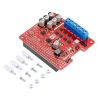
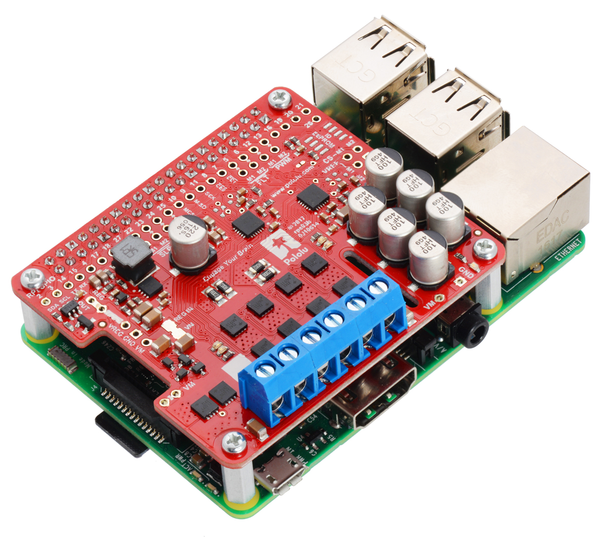
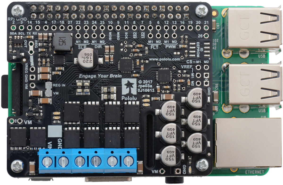
Pololu Dual G2 High-Power Motor Driver 24v14 for Raspberry Pi (Assembled)
Available with a lead time
Expect dispatch between Jul 31 and Aug 03
Quantity Discounts:
- 5+ $113.41 (exc GST)
- 10+ $109.86 (exc GST)
 |
These G2 dual high-power motor drivers are add-on boards for the Raspberry Pi, featuring pairs of discrete MOSFET H-bridges designed to drive two large brushed DC motors. They are designed to mount on and plug into compatible Raspberry Pi boards (Model B+ or newer), including the Pi 3 Model B and Model A+. Four versions are available so you can pick the one with the appropriate operating voltage range and output current capabilities for your project:
 Dual G2 High-Power Motor Driver18v22 for Raspberry Pi Dual G2 High-Power Motor Driver18v22 for Raspberry Pi |  Dual G2 High-Power Motor Driver18v18 for Raspberry Pi Dual G2 High-Power Motor Driver18v18 for Raspberry Pi |  Dual G2 High-Power Motor Driver24v18 for Raspberry Pi Dual G2 High-Power Motor Driver24v18 for Raspberry Pi |  Dual G2 High-Power Motor Driver24v14 for Raspberry Pi Dual G2 High-Power Motor Driver24v14 for Raspberry Pi | |
|---|---|---|---|---|
| Absolute maxinput voltage: | 30 V | 36 V* | ||
| Max nominalbattery voltage: | 18 V | 28 V | ||
| Max continuouscurrent per channel: | 22 A | 18 A | 18 A | 14 A |
| Default active current-limiting threshold: | 60 A | 50 A | 40 A | |
| Available withconnectors installed? | No | Yes | No | Yes |
* 40 V if regulator is disconnected
The minimum operating voltage for all four versions is 6.5 V, while the maximum operating voltages are given in the above table. The board also includes an integrated 5 V, 2.5 A switching step-down regulator that can be used to power the Raspberry Pi it is plugged into, enabling operation from a single power supply.
The driver’s default configuration uses six GPIO pins to control the motor drivers, making use of the Raspberry Pi’s hardware PWM outputs, and it uses two additional pins to read status outputs from the drivers. However, the pin mappings can be customized if the defaults are not convenient, and pins for current sensing and limiting are accessible on the board for more advanced applications.
|
|

The board matches the Raspberry Pi HAT (Hardware Attached on Top) mechanical specification, although it does not conform to the full HAT specifications due to the lack of an ID EEPROM. (A footprint for adding your own EEPROM is available for applications where one would be useful; pull-ups on SDA, SCL, and WP are provided.) It is not practical to use this expansion board with the original Raspberry Pi Model A or Model B due to differences in their pinout and form factor.
These dual motor drivers are also available as Arduino shields. For single-channel versions in a more compact form factor, consider Pololu's High-Power Motor Drivers. For smaller, lower power, and lower cost alternatives designed for a Raspberry Pi, consider Pololu's Dual MC33926 Motor Driver for Raspberry Pi, Dual MAX14870 Motor Driver for Raspberry Pi, and DRV8835 Dual Motor Driver for Raspberry Pi.
Features common to all versions
- PWM operation up to 100 kHz
- Motor indicator LEDs show what the outputs are doing even when no motor is connected
- Integrated 5 V, 2.5 A switching step-down voltage regulator powers the Raspberry Pi base for single-supply operation
- Python library makes it easy to get started using this board as a motor driver expansion board
- GPIO pin mappings can be customized if the default mappings are not convenient
- Current sensing and limiting pins are exposed for advanced use
- Reverse-voltage protection
- Undervoltage shutdown
- Short circuit protection
Details for item #3753
|
|
- Operating voltage: 6.5 V to 36 V (absolute maximum; not intended for use with 36 V batteries)
- Maximum can be increased to 40 V if regulator is disconnected (see below)
- Output current: 14 A continuous
- Active current limiting (chopping) with approximate default threshold of 40 A (can be adjusted lower)
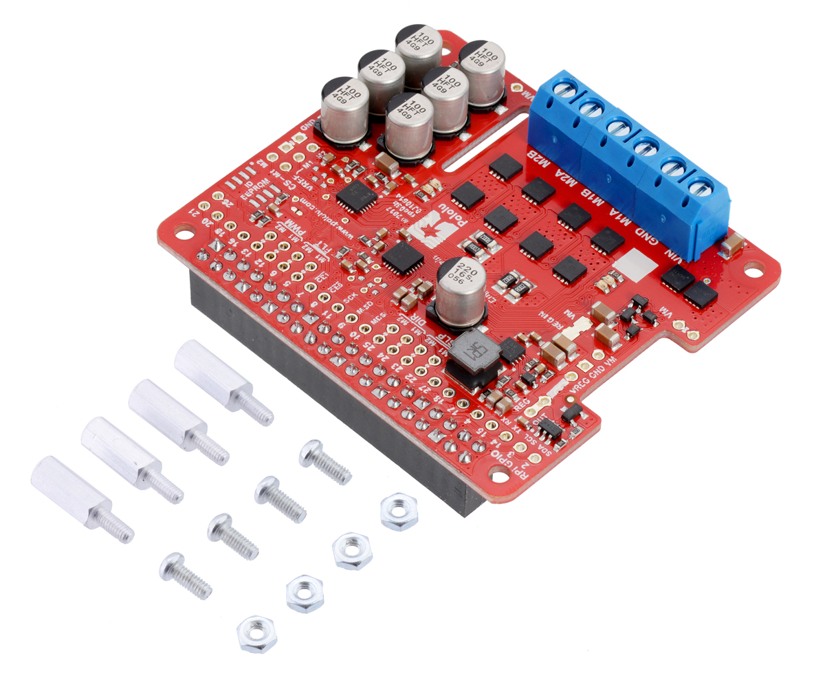
This version of the 24v14 motor driver is fully assembled, with a 2×20-pin 0.1" female header (for the Raspberry Pi interface) and a six-pin strip of 5 mm terminal blocks (for board power and motor outputs) soldered in. It can be distinguished from the other versions by its red PCB and the number 100 on top of the six tall silver electrolytic capacitors at the corner of the board. (See item #3752 for a kit version with connectors included but not soldered in.)
 |
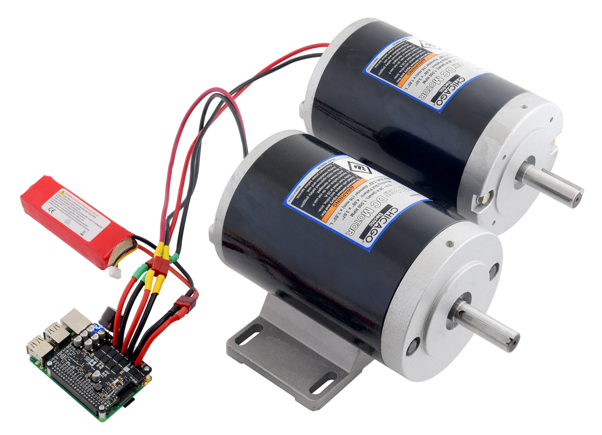
Pololu Dual G2 High-Power Motor Driver 24v14 for Raspberry Pi (assembled version) with included hardware. |
|---|
Four M2.5 standoffs (11 mm length), screws, and nuts are included to secure the board to the Raspberry Pi at the proper height for the GPIO connector.
Shorting blocks and 0.1" male headers (not included) can be used to make some of the more advanced optional modifications to the board, such as remapping the control pins.
The motor driver includes six 100 µF or 150 µF electrolytic power capacitors, and there is room to add additional capacitors (e.g. to compensate for long power wires or increase stability of the power supply). Additional power capacitors are usually not necessary, and no additional capacitors are included with this motor driver.
A Raspberry Pi is not included.
Using the motor driver board
 |
Power
An appropriate motor power supply should be connected to the motor driver’s large VIN and GND pads. The board includes a reverse-voltage protection circuit that helps prevent damage in case the motor power supply is connected backward. The reverse-protected input voltage can be accessed for use in other circuits through the two pins labeled VM on the left side of the board. By default, the motor power supply also feeds a 5 V, 2.5 A switching step-down regulator that provides power to the connected Raspberry Pi.
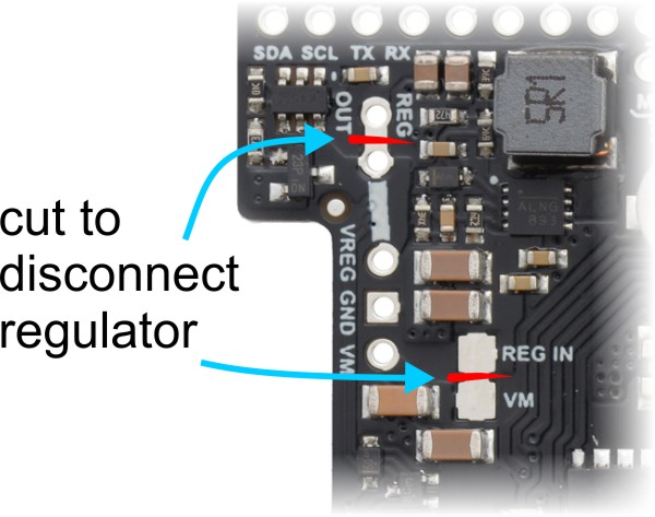 |
Disconnecting the regulator on the Dual G2 High-Power Motor Driver for Raspberry Pi. |
|---|
An ideal diode circuit on this board prevents reverse current from flowing into the motor driver board’s 5 V supply if the Raspberry Pi is separately powered (for example, through its USB power receptacle). However, starting with the Raspberry Pi 3 Model B+, there is no corresponding ideal diode circuit on the Raspberry Pi’s USB power input, so it is possible for the driver board to backfeed a USB power adapter through the Raspberry Pi. As a result, Pololu do not recommend connecting external USB power to the Raspberry Pi while it is powered through the motor driver.
Backfeeding is not an issue with older Raspberry Pi versions, which do have a diode circuit on the USB power input. With Raspberry Pi versions prior to the Pi 3 B+, it is safe to have a different power supply connected to the Raspberry Pi through its USB receptacle while the motor driver is connected and powered.
If you want to power the Raspberry Pi separately, the regulator can be disconnected by cutting two exposed traces on the board: one between the surface-mount pads labeled “VM” and “REG IN”, and another between the two pins by the “REG OUT” label, as shown to the right. On the 24v14 and 24v18 versions, disconnecting the regulator increases the absolute maximum operating voltage of the board to 40 V.
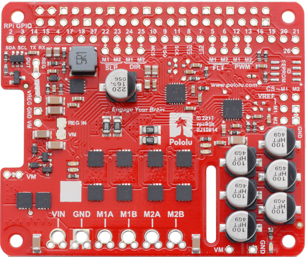
Default pin mappings
This table shows how the Raspberry Pi’s GPIO pins are used to interface with the motor drivers:
| RPiGPIO pin | Motor driver pin | Description |
|---|---|---|
| 5 | Motor 1 FLT | Fault indicator: When the driver channel is functioning normally, this pin should be pulled high by the Raspberry Pi. In the event of a driver fault, FLT is driven low. See below for details. |
| 6 | Motor 2 FLT | |
| 12 | Motor 1 PWM | Motor speed input: A PWM (pulse-width modulation) signal on this pin corresponds to a PWM output on the corresponding channel’s motor outputs. When this pin is low, the motor brakes low. When it is high, the motor is on. The maximum allowed PWM frequency is 100 kHz. |
| 13 | Motor 2 PWM | |
| 22 | Motor 1 SLP | Inverted sleep input: This pin is pulled low by default, putting the motor driver channel into a low-current sleep mode and disabling the motor outputs (setting them to high impedance). SLP must be driven high to enable the motor channel. |
| 23 | Motor 2 SLP | |
| 24 | Motor 1 DIR | Motor direction input: When DIR is low, motor current flows from output A to output B; when DIR is high, current flows from B to A. |
| 25 | Motor 2 DIR |
Motor control options
With the PWM pin held low, both motor outputs will be held low (a brake operation). With PWM high, the motor outputs will be driven according to the DIR input. This allows two modes of operation: sign-magnitude, in which the PWM duty cycle controls the speed of the motor and DIR controls the direction, and locked-antiphase, in which a pulse-width-modulated signal is applied to the DIR pin with PWM held high.
In locked-antiphase operation, a low duty cycle drives the motor in one direction, and a high duty cycle drives the motor in the other direction; a 50% duty cycle turns the motor off. A successful locked-antiphase implementation depends on the motor inductance and switching frequency smoothing out the current (e.g. making the current zero in the 50% duty cycle case), so a high PWM frequency might be required.
| Inputs | Outputs | Operation | |||
|---|---|---|---|---|---|
| SLP | DIR | PWM | MxA | MxB | |
| 1 | 0 | PWM | PWM (H/L) | L | forward/brake at speed PWM % |
| 1 | 1 | PWM | L | PWM (H/L) | reverse/brake at speed PWM % |
| 1 | X | 0 | L | L | brake low (outputs shorted to ground) |
| 0 | X | X | Z | Z | coast (outputs off) |
PWM frequency
The motor driver supports PWM frequencies as high as 100 kHz, but note that switching losses in the driver will be proportional to the PWM frequency. Typically, around 20 kHz is a good choice for sign-magnitude operation since it is high enough to be ultrasonic, which results in quieter operation.
A pulse on the PWM pin must be high for a minimum duration of approximately 0.5 µs before the outputs turn on for the corresponding duration (any shorter input pulse does not produce a change on the outputs), so low duty cycles become unavailable at high frequencies. For example, at 100 kHz, the pulse period is 10 µs, and the minimum non-zero duty cycle achievable is 0.5/10, or 5%.
Fault conditions
The motor driver can detect several fault states that it reports by driving the FLT pin low; this is an open-drain output that should be pulled up to your system’s logic voltage. The detectable faults include short circuits on the outputs, under-voltage, and over-temperature. All of the faults disable the motor outputs but are not latched, meaning the driver will attempt to resume operation when the fault condition is removed (or after a delay of a few milliseconds in the case of the short circuit fault). The over-temperature fault provides a weak indication of the board being too hot, but it does not directly indicate the temperature of the MOSFETs, which are usually the first components to overheat, so you should not count on this fault to prevent damage from over-temperature conditions.
Remapping pins
All of the Raspberry Pi’s GPIO pins are broken out along a row of numbered through-holes just below the 40-pin GPIO connector. Each GPIO pin used by the board is connected from this row to the corresponding motor driver pin by a trace on the top side of the board spanning the pair of holes. If you want to remap one of these motor driver pins, you can cut its trace with a knife and then run a wire from the lower hole to a new GPIO pin.
 |
Dual G2 High-Power Motor Driver for Raspberry Pi remapping example: moving M2DIR from GPIO pin 25 to pin 27. |
|---|
Note that the default pin mappings were chosen so that the Raspberry Pi’s default GPIO pull-ups and pull-downs match the direction the motor driver pins are or should be pulled (up for SF, down for others); if you remap the motor driver pins without paying attention to this, you might encounter issues with pins being pulled the wrong way. See the Raspberry Pi documentation for more about the default GPIO states.
 |
Current sensing and limiting pins on the Dual G2 High Power Motor Driver for Raspberry Pi. |
|---|
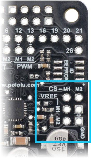
Current sensing and limiting
The motor driver exposes current sensing and limiting pins that are not connected to the Raspberry Pi, but they are accessible through their own through-holes in case you want to use them in a more advanced application.
The driver has the ability to limit the motor current through current chopping: once the motor drive current reaches a set threshold, the driver goes into brake mode (slow decay) for about 25 µs before applying power to drive the motor again. This makes it more practical to use the driver with a motor that might only draw a few amps while running but can draw many times that amount (tens of amps) when starting.
On this board (24v14), the nominal current limiting threshold is set to about 40 A by default. For each motor channel, you can lower the limit by connecting an additional resistor between the VREF pin and the adjacent GND pin; the graph below shows how the current limit relates to the VREF resistor value. For example, adding a 100 kO resistor between VREF and GND lowers the current limit to approximately 24 A. Note that the current limiting threshold is not highly precise, and is less accurate at especially low settings (indicated by the dashed portion of the curve).
 |
The driver’s current sense pins, labeled CS, output voltages proportional to the motor currents while the H-bridges are driving. The output voltage for this version is about 20 mV/A plus a small offset, which is typically about 50 mV.
Each CS output is only active while the corresponding H-bridge is in drive mode; it is inactive (low) when the channel is in brake mode (slow decay), which happens when the PWM input is low or when current limiting is active. Current will continue to circulate through the motor when the driver begins braking, but the voltage on the CS pin will not accurately reflect the motor current in brake mode. The CS voltage is used internally by the motor driver, so to avoid interfering with the driver’s operation, you should not add a capacitor to this pin or connect a load that draws more than a few mA from it.
Real-world power dissipation considerations
The MOSFETs can handle large current spikes for short durations (e.g. 100 A for a few milliseconds), and the driver’s current chopping will keep the average current under the set limit. The peak ratings are for quick transients (e.g. when a motor is first turned on), and the continuous rating is dependent on various conditions, such as the ambient temperature. PWMing the motor will introduce additional heating proportional to the frequency. The actual current you can deliver will depend on how well you can keep the motor driver cool. The driver’s printed circuit board is designed to draw heat out of the MOSFETs, but performance can be improved by adding a heat sink or air flow. For high-current installations, the motor and power supply wires should also be soldered directly instead of going through the supplied terminal blocks, which are rated for up to 16 A.
Warning: This motor driver has no over-temperature shut-off. An over-temperature or over-current condition can cause permanent damage to the motor driver. You might consider using either the driver’s integrated current sense output (with an external ADC) or an external current sensor to monitor your current draw.This product can get hot enough to burn under normal operating conditions. Take care when handling this product and other components connected to it.
Dimensions
| Size: | 65 mm × 56 mm |
|---|---|
| Weight: | 30 g1 |
General specifications
| Motor channels: | 2 |
|---|---|
| Minimum operating voltage: | 6.5 V |
| Maximum operating voltage: | 36 V2 |
| Continuous output current per channel: | 14 A3 |
| Maximum PWM frequency: | 100 kHz |
| Reverse voltage protection?: | Y |
| Partial kit?: | N |
Identifying markings
| PCB dev codes: | rpe03b |
|---|---|
| Other PCB markings: | 0J10614, blank white box |
Notes:
- 1
- Without included mounting hardware.
- 2
- Absolute maximum; higher voltages can permanently destroy the motor driver. Recommended maximum is approximately 30 V, which leaves a safety margin for ripple voltage on the supply line. Disconnecting on-board regulator increases absolute maximum to 40 V. Not recommended for use with 36 V batteries.
- 3
- Typical results at room temperature with both channels running at 90% duty cycle.
File downloads
-
Dimension diagram of the Pololu Dual G2 High-Power Motor Driver 18v18 or 24v14 for Raspberry Pi (464k pdf)
-
Dimension diagram of the Pololu Dual G2 High-Power Motor Driver 18v22 or 24v18 for Raspberry Pi (437k pdf)
-
3D model of the Pololu Dual G2 High-Power Motor Driver 18v18 or 24v14 for Raspberry Pi (17MB step)
-
3D model of the Pololu Dual G2 High-Power Motor Driver 18v22 or 24v18 for Raspberry Pi (17MB step)
-
Drill guide for the Pololu Dual G2 High-Power Motor Driver 18v18 or 24v14 for Raspberry Pi (196k dxf)
This DXF drawing shows the locations of all of the board’s holes.
-
Drill guide for the Pololu Dual G2 High-Power Motor Driver 18v22 or 24v18 for Raspberry Pi (196k dxf)
This DXF drawing shows the locations of all of the board’s holes.
Recommended links
-
Python library for the Pololu Dual G2 High Power Motor Drivers for Raspberry Pi
This Python library for the Raspberry Pi makes it easy to interface with a Pololu Dual G2 High-Power Motor Driver for Raspberry Pi and use it to drive a pair of brushed DC motors. An example program is included with the library.
Exact shipping can be calculated on the view cart page (no login required).
Products that weigh more than 0.5 KG may cost more than what's shown (for example, test equipment, machines, >500mL liquids, etc).
We deliver Australia-wide with these options (depends on the final destination - you can get a quote on the view cart page):
- $3+ for Stamped Mail (typically 10+ business days, not tracked, only available on selected small items)
- $7+ for Standard Post (typically 6+ business days, tracked)
- $11+ for Express Post (typically 2+ business days, tracked)
- Pickup - Free! Only available to customers who live in the Newcastle region (must order online and only pickup after we email to notify you the order is ready). Orders placed after 2PM may not be ready until the following business day.
Non-metro addresses in WA, NT, SA & TAS can take 2+ days in addition to the above information.
Some batteries (such as LiPo) can't be shipped by Air. During checkout, Express Post and International Methods will not be an option if you have that type of battery in your shopping cart.
International Orders - the following rates are for New Zealand and will vary for other countries:
- $12+ for Pack and Track (3+ days, tracked)
- $16+ for Express International (2-5 days, tracked)
If you order lots of gear, the postage amount will increase based on the weight of your order.
Our physical address (here's a PDF which includes other key business details):
40 Aruma Place
Cardiff
NSW, 2285
Australia
Take a look at our customer service page if you have other questions such as "do we do purchase orders" (yes!) or "are prices GST inclusive" (yes they are!). We're here to help - get in touch with us to talk shop.
Have a product question? We're here to help!

-
-
- ATmega168-20PU Atmel AVR MicrocontrollerSKU: 002-556-ATMEGA168-20PU Brand: Core Electronics8-bit Microcontroller - MCU 16kB Flash 0.5kB EEPROM 23 I/O Pins.


- Magnet Square - 0.125"SKU: COM-08644 Brand: SparkfunThese are very small rare earth magnets - 0.125" cubed. Composed of Neodymium/Ir ...
- 6.3:1 Metal Gearmotor 37Dx65L mm 24V with 64 CPR Encoder (Helical Pinion)SKU: POLOLU-4698 Brand: PololuThis gearmotor is a powerful 24V brushed DC motor with a 6.25:1 metal gearbox an ...
- 8421 Encoder-VerticalSKU: DFR0721 Brand: DFRobotThis is an 8421 absolute position encoder with 16-gear code(0-F). The mechanical ...
- OLED Display Module for Raspberry Pi Pico, 1.3inch, SPI/I2C (64×128)SKU: WS-19376 Brand: Waveshare1.3" OLED Display module an Embedded SH1107 Driver, Using SPI/I2C Bus.


Guides

The Maker Revolution
Projects

The Rats Nest VCC Desktop Power Supply

Remote-Controlled Mars Rover

FlipperMate: Hands-Free Pinball

Makers love reviews as much as you do, please follow this link to review the products you have purchased.
Product Comments