Note: This guide does not work with the Raspberry Pi 5. The Pi 5 handles its GPIO pins differently so the libraries used in this guide no longer work. A Pi 4 or older will still work just fine with this guide.
This guide will demonstrate exactly how to control Standard Stepper Motors and DC Motors with a Raspberry Pi Single-Board Computer. To do this as seamlessly as possible we will utilise a HAT. HAT stands for Hardware Attached on Top. HAT boards directly plug into the GPIO of the Raspberry Pi create a sturdy electrical connection. The best HAT for this application is the Adafruit DC & Stepper Motor HAT for Raspberry Pi. For a completely solderless solution, the Adafruit DC & Stepper Motor Bonnet for Raspberry Pi is for you! This has the form factor to perfectly fit over Raspberry Pi Zero but it will work with any and all Raspberry Pi computers in the same manner as demonstrated in this guide.
If you only want to control Two Stepper Motors or Four DC Motors with your Raspberry Pi this HAT has got you covered. Keep in mind that the Adafruit DC & Stepper Motor HAT is stackable. All communication is through I2C.
In general, this communication method enables one controller to manage up to 127 unique devices. In our situation here we can stack up to 32 Adafruit HATs on top of each other! This means you can control independently up to 128 DC Motors or up to 64 Stepper Motors all through a single Raspberry Pi Single Board Computer. Naturally, you can mix and match too.
- What You Need
- Stepper Motor or DC Motor Overview
- Hardware Assembly
- Software Set Up
- Code To Run DC Motors
- Code To Run Stepper Motors
- A Note on Stacking the HATs
- Download Python Scripts
The main difference between a motor controller and a motor driver is as follows: The motor controller is responsible for the controlling speed, torque, the direction of the motor. A motor driver is responsible to provide enough electrical power to the motor as per requirement. Check here for more on Motor Control vs Motor Drivers. We will use an official Raspberry Pi Power Supply (5V) that will power the Raspberry Pi and a separate power supply (5V to 12V) to power the Adafruit HAT and attached motors. Below is an image of the Hardware being utilised in this guide.
We will need to run programming scripts to get our Motors to rotate. The Python Programming Language will be used to create these scripts. This has an advantage over other programming languages (like C++) as its syntax can be more readily understood by a human. You can utilise other programming languages however here will demonstrate the most direct path for the quickest success. Thus, Python will be used. I have created a Python Workshop for Beginners so go check that out if you ever feel like you're treading water in the deep end.
If you happen to be holding a Raspberry Pi board and are not quite sure what it is? Then check out this guide Raspberry Pi Generations to identify it. As always if you have any questions, queries, thoughts, or comments please let me know!
What You Need
Below is a list of everything you will need to create a similar motor control system in your Makerverse.
- Any Raspberry Pi Single Board Computer (here I am using a Raspberry Pi 4 Model B 2GB. Note here - that very early versions of Raspberry Pi Single Board Computers have slightly different GPIO Pin arrangements than more recent ones. The HAT chosen can accommodate both styles. Be aware of this before overcommitting and soldering the incorrect header to the HAT)
- Micro-SD Card Flashed with Raspberry Pi OS (A guide to flash Micro-SD cards can be found here)
- Adafruit DC & Stepper Motor HAT for Raspberry Pi (Keep in mind that the headers will need to be soldered onto it to function correctly. These are supplied with the board. If you will stack multiple HAT boards on top of each other make sure you solder on stackable headers. These are different than the one that comes with the Adafruit board)
- A Standard 5V DC Motor
- A Standard Stepper Motor
- A 5V or 12V Power Supply (This will power the HAT and Motors, the choice depends on the Motors selected. Check the Specification/Datasheet found at the bottom of every product page)
- DC Barrel Jack Adapter for use with the DC Power Supply.
- Raspberry Pi 4 Official Power Supply
- Mouse and Keyboard
- Micro-HDMI to HDMI Cord to connect the system to a Monitor
- Jumper Wires Male to Female
- A Philips Head Screwdriver to connect wires to Screw Down Terminals
Worth noting here is that the HAT cannot power the Raspberry Pi. My recommended setup utilises two separate power supplies. One to power the Raspberry Pi and one to power the motor and HAT. Motors put a lot of noise onto a power supply and it can cause power draw stability problems. This is no good for a power-hungry Raspberry Pi Single Board Computer.
Stepper Motor or DC Motor Overview
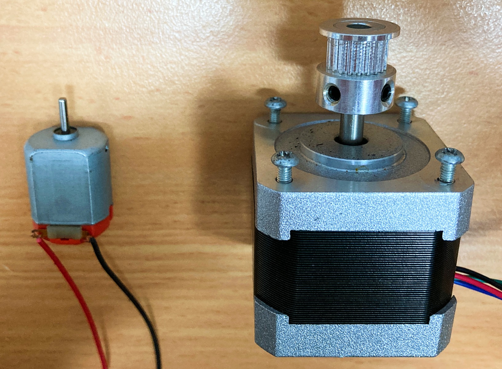
We want a fully customisable method of converting electrical energy into rotational energy (angular kinetic energy). Depending on your needs either a DC motor or a Stepper Motor is going to be preferable. You might want a device that can rotate at a certain speed (RPM, revolutions per minute). In that case, a DC motor is what you would want to use. You might want a device that rotates to a precise angular position, at a very precise speed, or a set amount of rotations. In this case, a Stepper motor is what you would want to use. See below for an image of a small DC motor on the left and a 5V compatible NEMA Stepper Motor on the right.
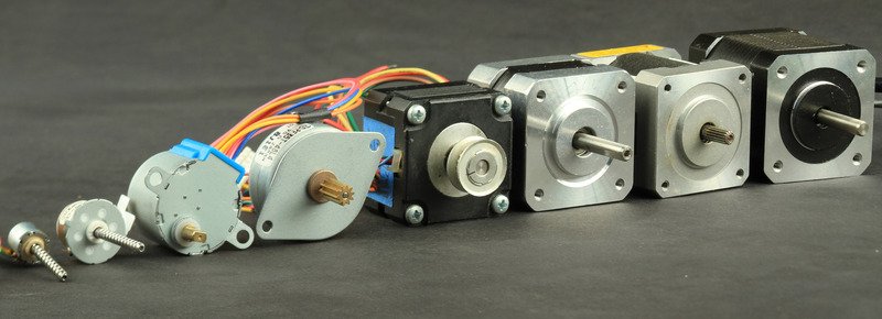
DC motors are available in a huge range of sizes. You can get very tiny motors to very large industrial motors capable of many kilowatts, and everything in between. They are lightweight, reasonably efficient, and have good torque. They come in Brushless or Brushed variants. Brushed Motors create a lot of electrical noise from the constantly switching physical commutator. That noise can find its way back into controlling circuitry and cause electrical issues. Brushless is the mechanically simpler DC motor variant. It replaces the physical commutator with an electrical commutation. These types of DC motors are often used in quad-copters and drones. Many DC motors run too fast to be useful so it has become standard to have complete DC Motor packages that include a gear train. This gear train reduces rotational top speed and increases peak torque. Keep in mind that gear trains do increase friction, do increase inertia, and can cause a backlash if there is sloppiness in the gear train tolerances. Next two images I would like to thank Adafruit very kindly for creating them. They are both beautiful bouquets of electronic hardware. See a whole bunch of DC motor styles on the right of the image below, some stepper motor variants in the middle, and some servos variants on the left. Check here for more about DC Motors.

Stepper motors are DC motors that move in discrete steps. They have multiple coils that are organized in groups/phases. By energizing each phase in sequence, the stepper motor will rotate. Throw in some computer control and you can achieve very precise positioning and rotational speed control. For this reason, stepper motors are utilised in almost all precision motion control applications. Take a look at any consumer 3D Printer or CNC Machine and you will very quickly identify a stepper motor. General Positives are great Positioning, strong Low-Speed Torque, and great Speed control. General Limitations are Lower Efficiency (when compared to DC motors), Limited High-Speed Torque, and No Looping Feedback regarding instantaneous positioning (as you get with Servo motors). This lack of Looping Feedback is the reason why many Stepper Motor projects often require limit switches to correctly Home the stepper motors in the system. See a whole bunch of commonly encountered stepper motors in the image below, the small ones are super cute! Check here for more on Stepper Motors.
Be aware that there are other options when it comes to turning electrical energy into rotational energy. Servos are an immensely useful way to turn electrical energy into a rotational or linear motion with high efficiency and with great precision. Information on the desired position is sent via a PWM signal. Continuous Servo motors are a variation of the standard servo. These can spin continuously and are controlled by a Raspberry Pi differently with control over the speed and direction instead of position. Come check this guide to learn how to set up Standard servos to run with a Raspberry Pi Single Board Computer. Come check this guide to see how to control hundreds of Servos with a Raspberry Pi Single Board Computer.
When it comes to DC Motor or Stepper Motor selection it is important to meet their power requirements. So lets pull focus back to the Adafruit DC and Stepper Motor Driver HAT (see it next to a Raspberry Pi Single Board Computer in the image below). The motor controllers on this HAT are designed to run from 5V to 12V. Weird motor problems are often due to voltage mismatches so double-check your specification sheets first when it comes to troubleshooting. Most tiny 1.5V-3V Motors are not going to work or will slowly become damaged by 5V power. It is OK to run Stepper Motors at lower-than-rated voltage. They will simply carry less current and deliver less torque. Each Motor Driver on the HAT is capable of pushing out 2A. This can get very hot if doing so for a long time. For high load situations to increase the longevity of the HAT put heat-sinks on top of the motor drivers. In the image below you can see small heatsinks have been installed directly on top of the two motor driver integrated circuits. Even small DC motors can draw up to 3 Amps when they stall!

Hardware Assembly
The very first task is to assemble the Screwdown Terminals and Header onto the PCB of the Adafruit HAT. Every single through hole pin of this hardware will need to be soldered. See this task broken down into steps in the image below. This image demonstrates exactly how I went about soldering as well as some soldering tools and tips to make it easy. In Flux we trust! Using flux definitely makes soldering easier and much more consistent. My Soldering Iron Preference is the Hakko FX-888D, learn all about it here.

With the HAT now completely assembled we can turn our attention to attaching the HAT to the top of the Raspberry Pi. Do so by lining up the headers of the HAT with the GPIO pins of the Raspberry Pi. Then push both boards firmly together. Take care that all the pins are correctly lined up and that the HAT is fully seated. See this happening in the image below. You can also use Nylon Stand-offs and Screws to secure the two boards even more.

Having attached the HAT to the Raspberry Pi it will look like the image below. With that complete, we can now turn our attention to attaching the desired DC Motor and Stepper Motor to the HAT. The image below has highlighted the Screw Down Terminal Blocks that we will utilise to attach this hardware. We will need a Philips Head Screwdriver to effectively use these screw down terminals.

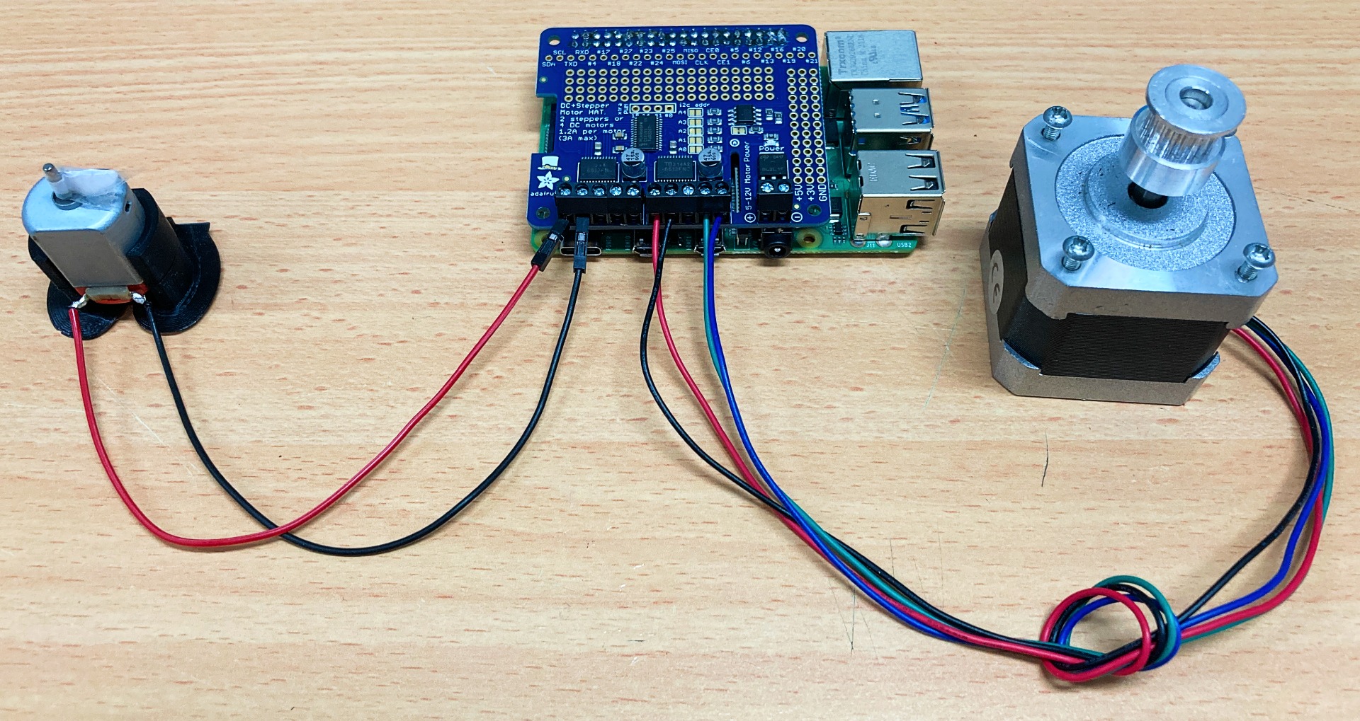
We will now connect up a DC motor to the HAT. To do this we will need wires that come off the DC motor which you may need to solder on. With that complete connect this DC motor to the | M1 | section. This is written on the PCB of the Adafruit HAT. In code, we will refer to and identify the target motors by these Port numbers written on the PCB board. Plug your red wire from the DC Motor to the furthest left Screw-Down Terminal. Connect the black wire to the Screw-Down Terminal directly next to the first.
Then turn attention to connecting a Stepper Motor to the HAT. We will connect it to the Screw-Down Terminal blocks labelled | M3 | and | M4 |. There are two main types of stepper motor, Uni-Polar and Bi-Polar. Uni-Polar Stepper Motors have 5 wires to connect. You will need to identify which wire is the Centre Tap and connect that one to the Center GND Screw-Down Terminal. The remaining 4 wires make up Two Coil Loops. You can Identify a Coil Pair by checking the end of two wires for continuity with a Multimeter. If the Multimeter beeps (confirming continuity) you have identified coil pair. Trial and error works here too. You will not break the Stepper motor by wiring it incorrectly. Connect a Coil Pair to the | M3 | Screw-Down Terminals and the other two wires to the | M4 | Screw-Down Terminals. Bi-Polar Stepper Motors have 4 Wires to connect. Do the same as before except ignore the Center GND Screw-Down Terminal. The Python code will be exactly the same for these two types of Stepper Motors. See the image below for a DC motor and a Bi-Polar Stepper Motor connected to the HAT correctly in the image below.
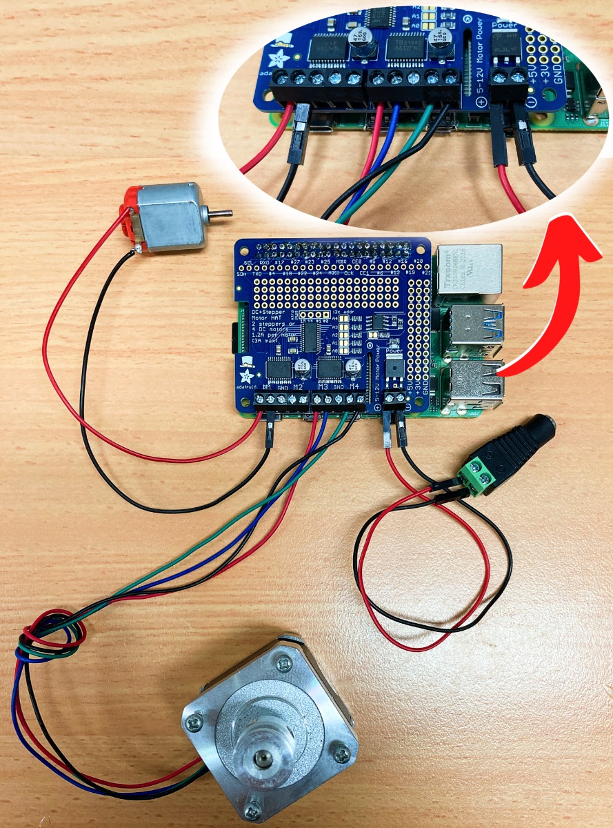
Note regarding the above image, we have also connected a female DC Power Jack correctly to the Positive and Negative Power Input on the bottom right of the HAT. This will make it easy to connect up a standard 5V Power Supply to the HAT.
With that complete, insert a micro-SD card flashed with Raspberry Pi OS and hook it up as a desktop computer. Add a mouse, keyboard, HDMI to a monitor. Then power up the Raspberry Pi System by plugging in a USB-C connector. Take the time to consider putting small heatsinks onto the motor driver integrated circuits of the HAT (see the previous chapter for this). See all of these parts, as well as the mouse and keyboard, attached together below.

Software Set Up.
Some packages will need to be installed to your fresh version of Raspberry Pi OS. This will allow correct communication between the Adafruit HAT and your Raspberry Pi. With the power into to the system and the (new) first boot-up wizard complete, you will be welcomed by the Raspberry Pi Desktop.
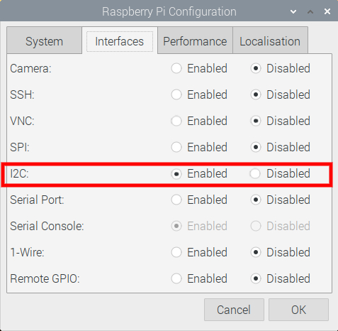
Now the Adafruit DC & Stepper Motor HAT requires I2C communication to work. By default on Raspberry Pi OS this communication method is turned off. So the first step is to turn that on. To do this open up the Raspberry Pi Configuration menu (found using the top left menu and scrolling over Preferences) and then enable the I2C Connection found under the Interfaces tab. After enabling, reset the Raspberry Pi to lock in the change. See the Raspberry Pi Configuration menu in the image below with the I2C toggle setting enabled.
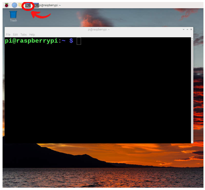
Now with your system rebooted and connected to the internet, open a new terminal window by pressing the black button on the top left of the screen. This will open up a terminal window. See the image below of this happening and a big red arrow pointing towards the terminal button that was pressed.
This terminal window will enable us to download from the internet the exact packages we require. So now type and enter the following lines into the terminal to get all the packages that you will need. If prompted, type and enter | Y | to continue/confirm installations. See further below an image of one of these commands being downloaded.
sudo apt-get update
sudo pip3 install adafruit-circuitpython-motorkit

Once completed we have fully set up our Raspberry Pi Single Board Computer to work with the Adafruit DC & Stepper Motor HAT.
Code To Run DC Motor
This Adafruit DC & Stepper Motor HAT can drive 4 DC motors bi-directionally. That means they can spin clockwise and anti-clockwise on demands. The speed can be varied at 0.5% increments. Each motor can be driven up to 1.2 A Continuously or 3 Amp Peak. Check the specific Motor datasheets on motors you want to run to confirm that they will run at these current levels.
There are a lot of ways you can get the Raspberry Pi to activate the connected DC Motor. I will do the most intuitive by directly writing Python Scripts to control it. With the new first start wizard completed, you should currently see the familiar Raspberry Pi desktop.
From here open up a Python Interface like Thonny IDE. Thonny IDE is just a Python Interpreter Software and you can use whichever is your preference. Click on the Application Menu (this is the Raspberry Pi Symbol on the top left of the screen and hover over the Programming Tab to find them). Then copy and paste the following code into the coding area. You can also download all scripts utilised in this guide in a Zip file found at the bottom of the page.
# Below imports all necessary packages to make this Python Script run
import time
import board
from adafruit_motorkit import MotorKit

# Below initialises the variable kit to be our I2C Connected Adafruit Motor HAT. If stacking Multiple
# Adafruit HATs we can then explain in code exactly which I2C address we want focused on here.
kit = MotorKit(i2c = board.I2C())

# Below will provide the DC Motor maximum current available. This allows it to rotate at top speed clockwise
kit.motor1.throttle = 1.0

# This will create a 4 second break until the next command. Note that the above command continues to have effect
# as the motor will continue to spin at top speed
time.sleep (4)

# Below will provide the DC Motor half maximum current available. This allows it to rotate at half speed clockwise
kit.motor1.throttle = .5

# This will create a 4 second break until the next command. Note that the above command continues to have same effect
time.sleep (4)

# Below will provide the DC Motor Third maximum current available. This allows it to rotate at third speed anti-clockwise
# Note the negative symbol which allows it to spin in the other direction.
kit.motor1.throttle = - 0.3333

# This will create a 4 second break until the next command. Note that the above command continues to have same effect
time.sleep (4)

# Below will energise the DC Motor however it will not rotate. This is not the same as None which would de-energise the motor.
# Thus, with the below active, the DC motor would not be free spinning
kit.motor1.throttle = 0

# This will create a 4 second break until the next command. Note that the above command continues to have same effect
time.sleep (4)

# Below will not energise the DC Motor allowing it to freely spin.
kit.motor1.throttle = None
Allow me to simply explain this code. The first three lines set up all the necessary information the script needs by importing functionality. It then initialises a variable named | kit | to identify and quickly call the I2C connected HAT. The next line will then make the Raspberry Pi power the DC Motor with the Maximum amount of current available. This will make it rotate at top speed clockwise. The Raspberry Pi will then wait for four seconds, the motor will continue spinning during this period. This process is then repeated with different speeds and directions being utilised. Lastly the line | kit.motor1.throttle = None | will stop all current going through the DC Motor and leave it free-spinning. This is different from setting the throttle to 0 as doing that won't let the DC motor freely spin. See below for what this script looks like opened up in Thonny IDE on Raspberry Pi OS.

Now let's save the script (name it as anything you would like to), keep your hands away from any potentially spinning machinery, and run the code by pressing the big green button inside Thonny IDE. You should now have a successfully spinning DC Motor! Nice. See the DC motor with a little fan attached spinning happily in the image below.

The code here you can alter to make whatever speed or direction you want. For example, if we added a | - | to the line | kit.motor1.throttle = 1.0 | like so | kit.motor1.throttle = - 1.0 | the result will rotate the shaft in the opposite direction. If we lower the | 1 | number at the end of that line we will get a slower top speed.
If the Python Script or Raspberry Pi stops responding, the DC motor will continue performing its last request forever. A DC motor only needs a constant voltage across a single coil for movement. It is valuable to know what can be achieved with ultra-limited hardware. For brevity look below to see an image of the most hardware stripped-back version of powering a brushed DC Motor. You would not be able to do this with a brushless DC Motor. The motor will rotate at the max speed that the Voltage and Current delivery of the Battery can allow for. No Direction or speed control is possible. The battery can be thought of as a Motor Driver. The Raspberry Pi System can be thought of as a Motor Controller.

Code To Run Stepper Motors
Stepper Motors are different to DC motors thus the script needed to run it correctly will be different as well. The script however shares a lot of similarities with previous script. Particularly in regards to the first couple of lines that set up all the necessary information the script will need by importing functionality. To run this script open up Thonny IDE just like before. Copy and paste the below into your Thonny IDE instance just like the image below. You can also download all scripts utilised in this guide in a Zip file found at the bottom of the page.
# Below imports all neccessary packages to make this Python Script run
import time
import board
from adafruit_motor import stepper
from adafruit_motorkit import MotorKit

# Below initialises the variable kit to be our I2C Connected Adafruit Motor HAT
kit = MotorKit(i2c=board.I2C())

# If you uncomment below it will start by de-energising the Stepper Motor,
# Worth noting the final state the stepper motor is in is what will continue.
# Energised Stepper Motors get HOT over time along with the electronic silicon drivers

# kit.stepper1.release()

# The below loop will run 500 times. Each loop it will move one step, clockwise, then pause for 0.01 seconds
# This will almost look like a smooth rotation.

for i in range(500):

    kit.stepper2.onestep()
    time.sleep(0.01)

# The below loop will run 500 times. Each loop it will move two step, anti-Clockwise, then pause for 0.01 seconds
# This will almost look like a smooth rotation.

for i in range(500):

    kit.stepper2.onestep(direction=stepper.BACKWARD, style=stepper.DOUBLE)
    time.sleep(0.01)

# The below loop will run 500 times. Each loop it will move a Micro-step, anti-Clockwise, then pause for 0.01 seconds
# This will rotate very very slowly.

for i in range(500):

    kit.stepper2.onestep(direction=stepper.BACKWARD, style=stepper.MICROSTEP)
    time.sleep(0.01)

# The below line will de-energise the Stepper Motor so it can freely move
kit.stepper2.release()

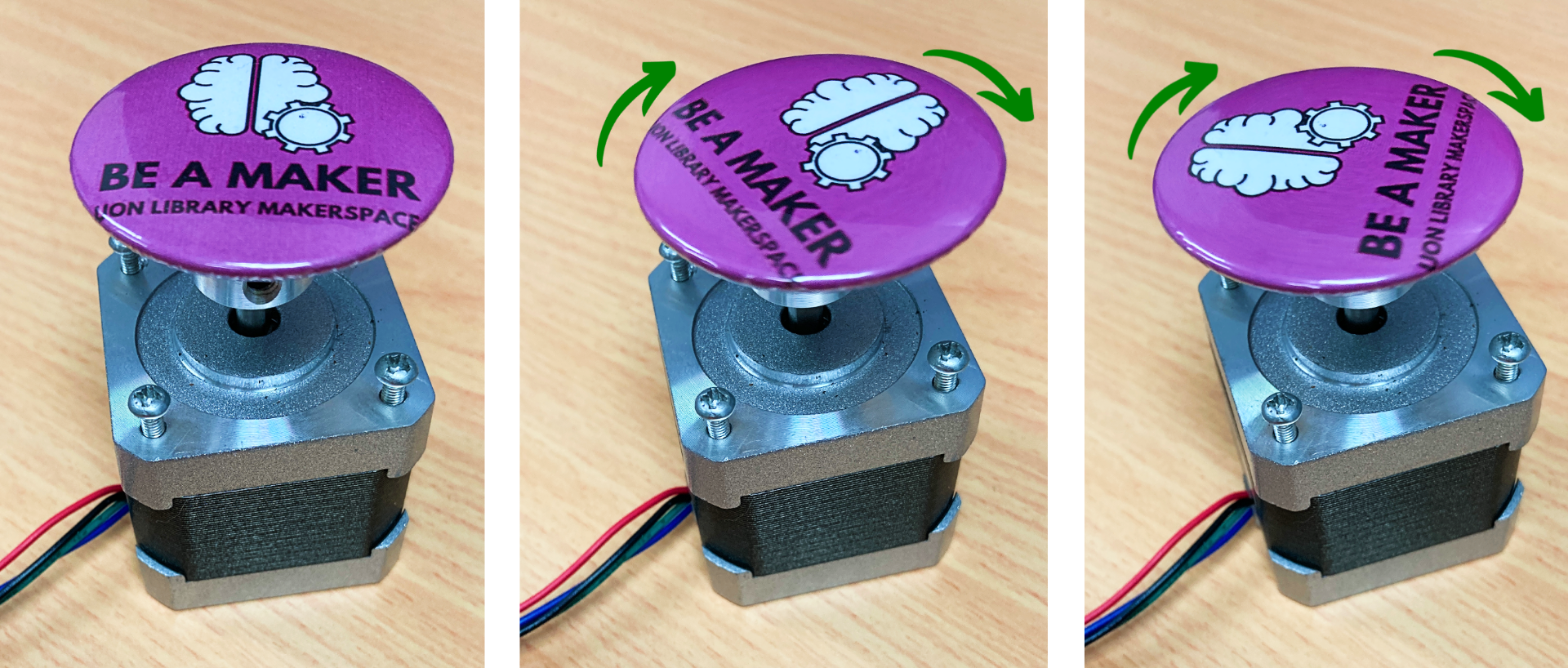
Then save your file (as anything you'd like to call it), make sure your hands are away from any spinning machinery, and press the big green run button. The second you do your stepper motor will spring to life! This script will first rotate the shaft 500 Full Steps every 0.01 seconds. To our human eyes, this looks like smooth movement but really it is a whole bunch of small steps repeated. Once it has done that it will go in the opposite direction using Double Steps. This will rotate twice as fast as before. This demonstrates that there are different ways to step through rotation. Once it does that for 500 steps it then continues rotating in the same direction of rotation very slowly as it is now utilising Micro-Stepping. Micro-Stepping is a way to break down each step into even smaller segments, allowing even more control over the exact angular positioning of the stepper motor. See the Stepper Motor rotating in the image below.
A Note on Stacking the HATs
Each board in a HAT stack needs a unique I2C address. On the top side of the board is solderable address jumpers. If you solder these connections together you will be able to change the default I2C Address of the board. Having done that you will be able to stack and communicate to them correctly. For example, in if you solder the second jumper you will need to set that new I2C address into your Python Script, | Kit1 = MotorKit() | is for default. That would be changed to | Kit1 = MotorKit(address=0x61) | when the second jumper is soldered together.

Download Python Scripts
Here is a Download Link for all the Python Scripts utilised in this guide. For ideas on what to do with Motor Control to just check out this!

