


Dual/Single Motor Driver Carrier TB67H420FTG
Available with a lead time
Expect dispatch between Aug 06 and Aug 10
Quantity Discounts:
- 10+ $18.67 (exc GST)
- 25+ $18.09 (exc GST)
 |
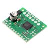
TB67H420FTG Dual/Single Motor Driver Carrier, bottom view with dimensions. |
|---|
The TB67H420FTG from Toshiba is an H-bridge motor driver IC that can be used for bidirectional control of one or two brushed DC motors at 10 V to 47 V. It can supply up to about 1.7 A continuously to each of two separate motors or about 3.4 A to a single motor, and it can tolerate peak currents up to 4.5 A per channel (dual) or 9 A (single) for a few seconds, making it a good choice for small- to medium-sized motors that run at higher voltages. The TB67H420FTG is a great IC, but its small surface-mount package makes it difficult for the typical student or hobbyist to use; Pololu's breakout board makes it easy to use with standard solderless breadboards and 0.1" perfboards. Since this board is a carrier for the TB67H420FTG, Pololu recommend careful reading of the TB67H420FTG datasheet (460k pdf). The board ships populated with SMD components, including the TB67H420FTG and a reverse battery protection circuit.
Features
- Single- or dual-channel H-bridge motor driver (can drive one or two DC motors)
- Motor supply voltage: 10 V to 47 V
- Output current:
- up to 1.7 A continuous (4.5 A peak) per motor in dual-channel mode
- up to 3.4 A continuous (9 A peak) in single-channel mode
- Configurable current chopping actively limits motor current to 4.5 A per channel (dual) or 9 A (single) by default; can be lowered with external resistors or voltage sources
- No separate logic supply needed; inputs are 3V- and 5V-compatible
- Flexible input interface provides several options for control
- Under-voltage lockout and protection against over-current/short-circuit and over-temperature
- Open-load detection
- Carrier board adds reverse-voltage protection up to 40 V
- Active-low error outputs indicate over-current, over-temperature, or open-load condition
- Compact size (1.0" × 1.2")
- Exposed solderable ground pad below the driver IC on the bottom of the PCB
Note: the motor supply capacitors on this carrier are rated for 50 V; this is less margin than on most of Pololu's motor driver carriers, which have ICs with ratings of 40 V or less. Please keep this in mind if you want to push the high-voltage limit of this driver.
Included hardware
This product ships with all surface-mount components—including the TB67H420FTG driver IC—installed as shown in the product picture. However, soldering is required for assembly of the included through-hole parts: one 1×20-pin breakaway 0.1" male header and three 2-pin, 3.5 mm terminal blocks (for board power and motor outputs).
The 0.1" male header can be broken or cut into smaller pieces as desired and soldered into the smaller through-holes. These headers are compatible with solderless breadboards, 0.1" female connectors, and Pololu's premium and pre-crimped jumper wires. The terminal blocks can be soldered into the larger holes to allow for convenient temporary connections of unterminated power and motor wires (see Pololu's short video on terminal block installation). You can also solder your motor leads and other connections directly to the board for the most compact installation.
|
|


Using the motor driver
Motor and power connections are made on one side of the board and control connections are made on the other. The driver requires an operating voltage between 10 V and 47 V to be supplied to the power input, VIN. This input is reverse-protected up to 40 V, and the VM pin provides convenient access to the reverse-protected supply voltage.
In a typical application, three connections are used to control each motor driver channel: INx1 and INx2 to set the motor direction and PWMx to set the speed, resulting in drive-brake operation. The following simplified truth table shows how the driver operates with this control method:
| TB67H420FTG simplified truth table | |||||
|---|---|---|---|---|---|
| Inputs | Outputs | Operation | |||
| INx1 | INx2 | PWMx | x+ | x- | |
| 1 | 0 | PWM | PWM (H/L) | L | forward/brake at speed PWM % |
| 0 | 1 | L | PWM (H/L) | reverse/brake at speed PWM % | |
| 1 | 0 | 0 | L | L | brake low (outputs shorted to ground) |
| 0 | 1 | ||||
| 1 | 1 | X | |||
| 0 | 0 | X | Z | Z | coast (outputs floating/disconnected) (standby if all IN and PWM inputs are low) |
Note the special case when all six control inputs (INA1, INA2, PWMA, INB1, INB2, and PWMB) are low: this puts the driver into a lower-power standby mode and clears any active errors.
Alternatively, the control lines can be reduced to two pins per channel if PWM signals are applied directly to INx1 and INx2 with PWMx held high; this allows either drive/brake or drive/coast operation, depending on whether the non-PWMed input is held high or low, respectively. (Note that achieving drive/brake operation with this method requires inverted PWM signals; that is, with one IN pin PWMed and the other held high, the motor will drive while the PWM signal is low and brake while it is high.) The complete truth table below shows all possible combinations of the inputs and the driver outputs they produce:
| TB67H420FTG complete truth table | |||||
|---|---|---|---|---|---|
| Inputs | Outputs | Operation | |||
| PWMx | INx1 | INx2 | x+ | x- | |
| 0 | 0 | 0 | Z | Z | coast (standby if all IN and PWM inputs are low) |
| 1 | 0 | L | L | brake low | |
| 0 | 1 | ||||
| 1 | 1 | ||||
| 1 | 0 | 0 | Z | Z | coast |
| 1 | 0 | H | L | forward | |
| 0 | 1 | L | H | reverse | |
| 1 | 1 | L | L | brake low | |
By default, the TB67H420FTG runs in dual-channel mode and drives two motors independently, but it can optionally be configured to run in a paralleled single-channel mode, in which it can deliver about twice the current to a single motor. To select single-channel mode, connect the HBMODE pin to a logic high voltage; the adjacent VCC pin provides a convenient place to do so, either with a short piece of wire or with male header pins and a 0.1" shorting block.
In single-channel mode, the A+ and A- pins should be connected to form one motor output, and B+ and B- should be connected to form the other. The A inputs control the motor and the B inputs are not used; the driver enters standby mode when all three A control inputs are low.
|
|


The TB67H420FTG can detect several fault (error) states that it reports by driving one or both of the LO pins low (the datasheet describes what each combination of LO1 and LO2 means). Otherwise, these pins are pulled up to VCC (5 V) by the board. Errors are latched, so the outputs will stay off and the error flag(s) will stay asserted until the error is cleared by toggling standby mode or disconnecting power to the driver.
Pinout
 |
Pinout diagram of the TB67H420FTG Dual/Single Motor Driver Carrier. |
|---|
| PIN | Default State | Description – dual channel mode (HBMODE = LOW) | Description – single channel mode (HBMODE = HIGH) |
|---|---|---|---|
| VIN | 10 V to 47 V board power supply input (reverse-protected up to 40 V). | ||
| GND | Ground connection points for the motor and logic supplies. The control source and the motor driver must share a common ground. | ||
| VM | These pins give access to the motor power supply after the reverse-voltage protection MOSFET (see the board schematic below). They can be used to supply reverse-protected power to other components in the system. VM is generally intended as an output, but it can also be used to supply board power, and some of the VM and GND holes are spaced for the addition of an optional through-hole capacitor. | ||
| A+ | Motor A output +. | Motor output A (connect together). | |
| A- | Motor A output -. | ||
| B+ | Motor B output +. | Motor output B (connect together). | |
| B- | Motor B output -. | ||
| VCC | Regulated 5 V output: this pin gives access to the voltage from the internal regulator of the TB67H420FTG. The regulator can only provide a few milliamps, so the VCC output should only be used for logic inputs on the board, not for powering external devices. | ||
| INA1 | LOW | Control input for A+. PWM can be applied to this pin (typically done with PWMA high). | Control input for A+ and A-. PWM can be applied to this pin (typically done with PWMA high). |
| INA2 | LOW | Control input for A-. PWM can be applied to this pin (typically done with PWMA high). | Control input for B+ and B-. PWM can be applied to this pin (typically done with PWMA high). |
| PWMA | LOW | PWM input for channel A. | PWM input. |
| INB1 | LOW | Control input for B+. PWM can be applied to this pin (typically done with PWMB high). | Not used. |
| INB2 | LOW | Control input for B-. PWM can be applied to this pin (typically done with PWMB high). | Not used. |
| PWMB | LOW | PWM input for channel B. | Not used. |
| LO1 | HIGH | Error output 1: drives low when an over-current or over-temperature fault occurs. Otherwise, the board pulls this pin up to VCC. | |
| LO2 | HIGH | Error output 2: drives low when an open-load or over-temperature fault occurs. Otherwise, the board pulls this pin up to VCC. | |
| VREFA | Current chopping threshold reference for channel A. | Current chopping threshold reference. | |
| VREFB | Current chopping threshold reference for channel B. | Not used. | |
| TBLKAB | LOW | Blanking time configuration input (see datasheet). This input should not be changed while the board is powered. | |
| HBMODE | LOW | H-bridge drive mode configuration input: LOW selects dual-channel mode; HIGH selects single-channel mode. This input should not be changed while the board is powered. | |
Current limiting
The TB67H420FTG can actively limit the current through the motors by using a fixed-frequency PWM current regulation (current chopping). This carrier board connects voltage dividers to the VREFA and VREFB pins that set the reference voltage to about 3.6 V.
In dual channel mode, this results in a nominal current limit of 4.5 A per channel. You can lower the limit for each motor channel by adding a resistor between the corresponding VREF pin and GND, or you can apply a voltage (3.6 V max) directly to the VREF pin. The formula for the current chopping thresholds in dual-channel mode is
In single-channel mode, the default 3.6 V reference voltage results in a nominal single-channel current limit of 9 A. The formula for the current chopping threshold in single-channel mode is
Real-world power dissipation considerations
The TB67H420FTG datasheet recommends a maximum continuous current of 4.5 A, and this carrier board limits the motor current to the same amount. However, the chip by itself will typically overheat at lower currents. In Pololu's tests, Pololu found that the chip was able to deliver 4.5 A per channel for only a few seconds before the chip’s thermal protection kicked in and disabled the motor outputs; a continuous current of about 1.7 A per channel was sustainable for many minutes without triggering a thermal shutdown. Driving only one channel at a time increases the sustainable current to almost 2.5 A per channel, and in single-channel mode, the driver can deliver about 3.4 A continuously without overheating.
The actual current you can deliver will depend on how well you can keep the motor driver cool. The carrier’s printed circuit board is designed to help with this by drawing heat out of the motor driver chip. PWMing the motor will introduce additional heating proportional to the frequency.
This product can get hot enough to burn you long before the chip overheats. Take care when handling this product and other components connected to it.
Schematic diagram
 |
Schematic diagram of the TB67H420FTG Dual/Single Motor Driver Carrier. |
|---|
This diagram is also available as a downloadable pdf: TB67H420FTG dual/single motor driver carrier schematic (158k pdf)
People often buy this product together with:
 | Pololu 20D mm Metal Gearmotor Bracket Pair |
 | TB9051FTG Single Brushed DC Motor Driver Carrier |
 | 19:1 Metal Gearmotor 37Dx68L mm 12V with 64 CPR Encoder (Helical Pinion) |
Dimensions
| Size: | 1.2" × 1.0"1 |
|---|---|
| Weight: | 3.5 g1 |
General specifications
| Motor driver: | TB67H420FTG |
|---|---|
| Motor channels: | 2 |
| Minimum operating voltage: | 10 V |
| Maximum operating voltage: | 47 V2 |
| Continuous output current per channel: | 1.7 A |
| Continuous paralleled output current: | 3.4 A |
| Reverse voltage protection?: | Y2 |
Identifying markings
| PCB dev codes: | md35a |
|---|---|
| Other PCB markings: | 0J11169 |
Notes:
File downloads
-
Toshiba TB67H420FTG datasheet (460k pdf)
-
Schematic diagram of the TB67H420FTG Dual/Single Motor Driver Carrier (158k pdf)
-
Dimension diagram of theTB67H420FTG Dual/Single Motor Driver Carrier (184k pdf)
-
3D model of the TB67H420FTG Dual/Single Motor Driver Carrier (4MB step)
-
Drill guide for the TB67H420FTG Dual/Single Motor Driver Carrier (57k dxf)
This DXF drawing shows the locations of all of the board’s holes.
Recommended links
-
Toshiba’s product page for the TB67H420FTG brushed motor driver IC, with links to its most up-to-date datasheet in several languages, application notes, and other resources.
Exact shipping can be calculated on the view cart page (no login required).
Products that weigh more than 0.5 KG may cost more than what's shown (for example, test equipment, machines, >500mL liquids, etc).
We deliver Australia-wide with these options (depends on the final destination - you can get a quote on the view cart page):
- $3+ for Stamped Mail (typically 10+ business days, not tracked, only available on selected small items)
- $7+ for Standard Post (typically 6+ business days, tracked)
- $11+ for Express Post (typically 2+ business days, tracked)
- Pickup - Free! Only available to customers who live in the Newcastle region (must order online and only pickup after we email to notify you the order is ready). Orders placed after 2PM may not be ready until the following business day.
Non-metro addresses in WA, NT, SA & TAS can take 2+ days in addition to the above information.
Some batteries (such as LiPo) can't be shipped by Air. During checkout, Express Post and International Methods will not be an option if you have that type of battery in your shopping cart.
International Orders - the following rates are for New Zealand and will vary for other countries:
- $12+ for Pack and Track (3+ days, tracked)
- $16+ for Express International (2-5 days, tracked)
If you order lots of gear, the postage amount will increase based on the weight of your order.
Our physical address (here's a PDF which includes other key business details):
40 Aruma Place
Cardiff
NSW, 2285
Australia
Take a look at our customer service page if you have other questions such as "do we do purchase orders" (yes!) or "are prices GST inclusive" (yes they are!). We're here to help - get in touch with us to talk shop.
Have a product question? We're here to help!
 Solderless Breadboard Jumper Cable Wires (75 Pieces)SKU: CE00301 Brand: Core ElectronicsThese jumper wires feature a male pin at each end which is perfect for connectin ...
-
-
- Arduino Mega 2560 R3SKU: A000067 Brand: Arduino
The Arduino Mega 2560 is an update on the older Mega board and provides 54 di ...


- Teensy 4.1SKU: DEV-16771 Brand: TeensyThe Teensy 4.1 is newest iteration of the astoundingly popular development platf ...

Guides

The Maker Revolution
Projects

The Rats Nest VCC Desktop Power Supply

Remote-Controlled Mars Rover

FlipperMate: Hands-Free Pinball

Makers love reviews as much as you do, please follow this link to review the products you have purchased.
Product Comments