
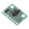


VL6180X Time-of-Flight Distance Sensor Carrier with Voltage Regulator, 60cm max
Available with a lead time
Expect dispatch between Jul 20 and Jul 23
Quantity Discounts:
- 10+ $27.71 (exc GST)
- 25+ $26.85 (exc GST)
 |
The VL6180X from ST Microelectronics is a sensor that combines proximity ranging and ambient light level measurement capabilities into a single package. This board is a carrier for the VL6180X, so Pololu recommend careful reading of the VL6180X datasheet (2MB pdf) before using this product.
Unlike simpler optical sensors that use the intensity of reflected light to detect objects, the VL6180 uses ST’s FlightSense technology to precisely measure how long it takes for emitted pulses of infrared laser light to reach the nearest object and be reflected back to a detector, making it essentially a short-range lidar sensor. This time-of-flight (TOF) measurement enables it to accurately determine the absolute distance to a target with 1 mm resolution, without the object’s reflectance influencing the measurement. The sensor is rated to perform ranging measurements of up to 10 cm (4"), but it can often provide readings up to 20 cm (8") with its default settings. Furthermore, the VL6180X can be configured to measure ranges of up to 60 cm (24") at the cost of reduced resolution, although successful ranging at these longer distances will depend heavily on the target and environment. (For more information, see “Range scaling factor” below.)
The VL6180 also includes an ambient light sensor, or ALS, that can measure the intensity of light with which it is illuminated. Ranging and ambient light measurements are available through the sensor’s I²C (TWI) interface, which is also used to configure sensor settings, and two independently-programmable GPIO pins can be configured as interrupt outputs.
The VL6180X is a great IC, but its small, leadless, LGA package makes it difficult for the typical student or hobbyist to use. It also operates at voltages below 3 V, which can make interfacing difficult for microcontrollers operating at 3.3 V or 5 V. Pololu's breakout board addresses these issues, making it easier to get started using the sensor, while keeping the overall size as small as possible.
The carrier board includes a low-dropout linear voltage regulator that provides the 2.8 V required by the VL6180X, which allows the sensor to be powered from a 2.7 V to 5.5 V supply. The regulator output is available on the VDD pin and can supply almost 150 mA to external devices. The breakout board also includes a circuit that shifts the I²C clock and data lines to the same logic voltage level as the supplied VIN, making it simple to interface the board with 3.3 V or 5 V systems, and the board’s 0.1" pin spacing makes it easy to use with standard solderless breadboards and 0.1" perfboards. The board ships fully populated with its SMD components, including the VL6180X, as shown in the product picture.
For similar, longer-range sensors, see Pololu's 200 cm VL53L0X carrier and 400 cm VL53L1X carrier. Pololu also have a 500 cm VL53L3CX carrier with the ability to detect multiple targets simultaneously and a 400 cm VL53L5CX carrier that can give measurements to multiple targets across a grid of up to 8×8 zones. (However, it is not practical to use the latter two sensors with typical 8-bit microcontrollers because of their RAM and program memory requirements.) All of these are physical drop-in replacements for the VL6180X carrier, but they have different APIs, so software for the VL6180X will need to be rewritten to work with the other sensors.
 |
 |
VL6180X datasheet graph of typical ranging performance. |
|---|
Specifications
- Dimensions: 0.5" × 0.7" × 0.085" (13 mm × 18 mm × 2 mm)
- Weight without header pins: 0.5 g (0.02 oz)
- Operating voltage: 2.7 V to 5.5 V
- Supply current: 5 mA (typical; varies with configuration, target, and environment)
- Output format (I²C): 8-bit distance reading (in millimeters), 16-bit ambient light reading
- Distance measuring range: up to 10 cm (4") specified; up to 60 cm (24") possible with reduced resolution. See the graph at the right for typical ranging performance.
- Ranging beyond 10 cm is possible with certain target reflectances and ambient conditions but not guaranteed by specifications. By default, the sensor can report distances up to 20 cm, or it can be configured to measure up to 60 cm with reduced resolution.
- The datasheet does not specify a minimum range, but in Pololu's experience, the effective limit is about 1 cm.
Included components
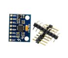
A 1×7 strip of 0.1" header pins and a 1×7 strip of 0.1" right-angle header pins are included, as shown in the picture below. You can solder the header strip of your choice to the board for use with custom cables or solderless breadboards, or you can solder wires directly to the board itself for more compact installations.
|
|


The board has two mounting holes spaced 0.5" apart that work with #2 and M2 screws (not included).
Using the VL6180X
Connections
At least four connections are necessary to use the VL6180X board: VIN, GND, SCL, and SDA. The VIN pin should be connected to a 2.7 V to 5.5 V source, and GND should be connected to 0 volts. An on-board linear voltage regulator converts VIN to a 2.8 V supply for the VL6180X IC.
The I²C pins, SCL and SDA, are connected to built-in level-shifters that make them safe to use at voltages over 2.8 V; they should be connected to an I²C bus operating at the same logic level as VIN.
The two GPIO pins are open-drain outputs pulled up to 2.8 V by the board (although GPIO0 defaults to being a chip enable input). They are not connected to level-shifters on the board and are not 5V-tolerant, but they are usable as-is with many 3.3 V and 5 V microcontrollers: the microcontroller can read the sensor’s output as long as its logic high threshold is below 2.8 V, and the microcontroller can alternate its own output between low and high-impedance states to drive the pin. Alternatively, Pololu's 4-channel bidirectional logic level shifter can be used externally with those pins.
 |
Pinout
| PIN | Description |
|---|---|
| VDD | Regulated 2.8 V output. Almost 150 mA is available to power external components. (If you want to bypass the internal regulator, you can instead use this pin as a 2.8 V input with VIN disconnected.) |
| VIN | This is the main 2.7 V to 5.5 V power supply connection. The SCL and SDA level shifters pull the I²C lines high to this level. |
| GND | The ground (0 V) connection for your power supply. Your I²C control source must also share a common ground with this board. |
| SDA | Level-shifted I²C data line: HIGH is VIN, LOW is 0 V |
| SCL | Level-shifted I²C clock line: HIGH is VIN, LOW is 0 V |
| GPIO0/CE | This pin is configured as a chip enable input on power-up of the VL6180X; the board pulls it up to VDD to enable the sensor by default. Driving this pin low puts the sensor into hardware standby. After the VL6180X powers up, this pin can be reconfigured as a programmable interrupt output (VDD logic level). This input/output is not level-shifted. |
| GPIO1 | Programmable interrupt output (VDD logic level). The VL6180X also drives this pin low when it is in hardware standby. This output is not level-shifted. |
Schematic diagram
 |
The above schematic shows the additional components the carrier board incorporates to make the VL6180 easier to use, including the voltage regulator that allows the board to be powered from a 2.7 V to 5.5 V supply and the level-shifter circuit that allows for I²C communication at the same logic voltage level as VIN. This schematic is also available as a downloadable PDF (90k pdf).
I²C communication
The VL6180X can be configured and its distance and ambient light readings can be queried through the I²C bus. Level shifters on the I²C clock (SCL) and data (SDA) lines enable I²C communication with microcontrollers operating at the same voltage as VIN (2.7 V to 5.5 V). A detailed explanation of the I²C interface on the VL6180X can be found in its datasheet (2MB pdf), and more detailed information about I²C in general can be found in NXP’s I²C-bus specification (1MB pdf).
The sensor’s 7-bit slave address defaults to 0101001b on power-up. It can be changed to any other value by writing one of the device configuration registers, but the new address only applies until the sensor is reset or powered off.
The I²C interface on the VL6180X is compliant with the I²C fast mode (400 kHz) standard. In Pololu's tests of the board, Pololu were able to communicate with the chip at clock frequencies up to 400 kHz; higher frequencies might work but were not tested.
Sample Code
Pololu have written a basic Arduino library for the VL6180X that makes it easy to interface this sensor with an Arduino or Arduino-compatible controller. The library makes it simple to configure the VL6180X and read the distance and ambient light level data through I²C. It also includes example sketches that show you how to use the library.
Protocol hints
The datasheet provides a lot of information about this sensor, but a lot of essential info – including a mandatory initialization sequence – can only be found in other documents. Picking out the important details can take some time. Here are some pointers for communicating with and configuring the VL6180X that Pololu hope will get you up and running a little bit faster:
- Unlike many other I²C sensors from ST, which use 8-bit register addresses, the VL6180X uses 16-bit register addresses.
- The sensor must be initialized with a particular sequence of settings on power-up or reset. This sequence is not covered in the datasheet, but it can be found in ST application note AN4545 (706k pdf) and design tip DT0037 (386k pdf). (Our Arduino library includes a function that performs this initialization.)
- The two documents above can also help you understand basic procedures for configuring the VL6180X and getting readings from it. Additional documents, providing details on many other aspects of the VL6180X, can be found on ST’s product page for the VL6180X.
- Both distance and ambient light measurements can be performed in either single-shot or continuous mode. In either mode, once each measurement is started, you must poll a status register to wait for it to complete. In continuous mode, you should ensure that the inter-measurement period you select is longer than the time it takes to actually perform each measurement.
Range scaling factor
Although the VL6180X specifications state a maximum “guaranteed” range of 10 cm, the sensor can report distances of up to 20 cm with its default settings. By configuring a range scaling factor, the potential maximum range of the sensor can be increased at the cost of lower resolution. Setting the scaling factor to 2 provides up to 40 cm range with 2 mm resolution, while a scaling factor of 3 provides up to 60 cm range with 3 mm resolution. In all cases, the reading is given as a number between 0 and 200; with the default 1× scaling, this corresponds directly to a distance in mm, but with 2× or 3× scaling, the raw reading will represent a measurement in units of 2 mm or 3 mm, respectively (so the reading should be multiplied by 2 or 3 to obtain a result in millimeters).
Range scaling is not mentioned in the VL6180X datasheet as of Rev 7, but it is available in the VL6180X API provided by ST (STSW-IMG003). Pololu's Arduino library also provides functions to set the range scaling factor.
People often buy this product together with:
 | VL53L0X Time-of-Flight Distance Sensor Carrier with Voltage Regulator, 200cm Max |
 | VL53L1X Time-of-Flight Distance Sensor Carrier with Voltage Regulator, 400cm Max |
 | Romi Chassis Kit - Black |
Dimensions
| Size: | 0.5" × 0.7" × 0.085"1 |
|---|---|
| Weight: | 0.5 g1 |
General specifications
| Resolution: | 1 mm2 |
|---|---|
| Maximum range: | 60 cm2 |
| Interface: | I²C |
| Minimum operating voltage: | 2.7 V |
| Maximum operating voltage: | 5.5 V |
| Supply current: | 5 mA3 |
Identifying markings
| PCB dev codes: | irs09a |
|---|---|
| Other PCB markings: | 0J9250 |
Notes:
- 1
- Without included optional headers.
- 2
- Datasheet specifies 10 cm maximum; ranging beyond 10 cm depends on configuration, target, and environment. Resolution must be reduced to measure beyond 20 cm.
- 3
- Typical average current draw; varies with configuration, target, and environment.
File downloads
-
VL6180X datasheet (2MB pdf)
Datasheet for the ST VL6180X proximity and ambient light sensing (ALS) module.
-
DT0037: VL6180X range and ambient light sensor quick setup guide (386k pdf)
-
VL6180X Time-of-Flight Distance Sensor Carrier schematic diagram (90k pdf)
Schematic diagram of the VL6180X Time-of-Flight Distance Sensor Carrier.
-
3D model of the VL6180X Time-of-Flight Distance Sensor Carrier with Voltage Regulator, 60cm max (3MB step)
-
Drill guide for the VL6180X Time-of-Flight Distance Sensor Carrier with Voltage Regulator, 60cm max (20k dxf)
This DXF drawing shows the locations of all of the board’s holes.
-
UM10204 I²C-bus specification and user manual (1MB pdf)
The official specification for the I²C-bus, which is maintained by NXP.
Recommended links
-
An Arduino library for interfacing with the VL6180X distance and ambient light sensor.
-
ST’s product page for the VL6180X, with links to application notes and other resources.
Exact shipping can be calculated on the view cart page (no login required).
Products that weigh more than 0.5 KG may cost more than what's shown (for example, test equipment, machines, >500mL liquids, etc).
We deliver Australia-wide with these options (depends on the final destination - you can get a quote on the view cart page):
- $3+ for Stamped Mail (typically 10+ business days, not tracked, only available on selected small items)
- $7+ for Standard Post (typically 6+ business days, tracked)
- $11+ for Express Post (typically 2+ business days, tracked)
- Pickup - Free! Only available to customers who live in the Newcastle region (must order online and only pickup after we email to notify you the order is ready). Orders placed after 2PM may not be ready until the following business day.
Non-metro addresses in WA, NT, SA & TAS can take 2+ days in addition to the above information.
Some batteries (such as LiPo) can't be shipped by Air. During checkout, Express Post and International Methods will not be an option if you have that type of battery in your shopping cart.
International Orders - the following rates are for New Zealand and will vary for other countries:
- $12+ for Pack and Track (3+ days, tracked)
- $16+ for Express International (2-5 days, tracked)
If you order lots of gear, the postage amount will increase based on the weight of your order.
Our physical address (here's a PDF which includes other key business details):
40 Aruma Place
Cardiff
NSW, 2285
Australia
Take a look at our customer service page if you have other questions such as "do we do purchase orders" (yes!) or "are prices GST inclusive" (yes they are!). We're here to help - get in touch with us to talk shop.
Have a product question? We're here to help!
 22pF Ceramic Disc CapacitorSKU: CE05189 Brand: Core Electronics50V Voltage Rating, 5% Tolerance. Single pitch lead spacing.
-
-
-

- MPU-6050 Module 3 Axis Gyroscope + AccelerometerSKU: 018-MPU-6050 Brand: Core ElectronicsA 3-axis gyroscope and 3-axis accelerometer housed on a development board ready ...
- DRV8835 Dual Motor Driver CarrierSKU: POLOLU-2135 Brand: PololuThis tiny breakout board for TI’s DRV8835 dual motor driver can deliver 1.2 A ...
- Pololu Wheel 32x7mm Pair - WhiteSKU: POLOLU-1088 Brand: PololuThese white plastic wheels have silicone tires measuring 32 mm (1.26″) in diam ...
- N20 DC Motor with Magnetic Encoder - 6V with 1:50 Gear RatioSKU: ADA4638 Brand: AdafruitThe first step in a robotics project is to get a motor spinning. Once you've don ...


Guides

The Maker Revolution
Projects

The Rats Nest VCC Desktop Power Supply

Remote-Controlled Mars Rover

FlipperMate: Hands-Free Pinball

Makers love reviews as much as you do, please follow this link to review the products you have purchased.
Product Comments