
Pololu High-Power Motor Driver 24v12
Retired Product
Search for an alternativeOverview
 |

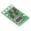
The Pololu high-power motor driver is a discrete MOSFET H-bridge designed to drive large DC brushed motors. The H-bridge is made up of one N-channel MOSFET per leg, and most of the board’s performance is determined by these MOSFETs (the rest of the board contains the circuitry to take user inputs and control the MOSFETs). The MOSFET datasheet (167k pdf) is available under the “Resources” tab. The absolute maximum voltage for this motor driver is 40 V, and higher voltages can permanently destroy the motor driver. Under normal operating conditions, ripple voltage on the supply line can raise the maximum voltage to more than the average or intended voltage, so a safe maximum voltage is approximately 34 V.
Note: Battery voltages can be much higher than nominal voltages when they are charged, so the maximum nominal battery voltage Pololu recommend is 28 V unless appropriate measures are taken to limit the peak voltage.
The versatility of this driver makes it suitable for a large range of currents and voltages: it can deliver up to 12 A of continuous current with a board size of only 1.3" by 0.8" and no required heat sink. With the addition of a heat sink, it can drive a motor with up to about 17 A of continuous current. The module offers a simple interface that requires as little as two I/O lines while allowing for both sign-magnitude and locked-antiphase operation. Integrated detection of various short-circuit conditions protects against common causes of catastrophic failure; however, please note that the board does not include reverse power protection or any over-current or over-temperature protection.
Using the Motor Driver
Connections
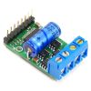
The motor and motor power connections are on one side of the board, and the control connections (5V logic) are on the other side. The motor supply should be capable of supplying high current, and a large capacitor should be installed close to the motor driver. The included axial capacitor can be installed directly on the board in the pins labeled '+' and '-' as shown below. Such installations are compact but might limit heat sinking options; also, depending on the power supply quality and motor characteristics, a larger capacitor might be required. There are two options for connecting to the high-power signals (V+, OUTA, OUTB, GND): large holes on 0.2" centers, which are compatible with the included terminal blocks, and pairs of 0.1"-spaced holes that can be used with perfboards, breadboards, and 0.1" connectors.
Warning: Take proper safety precautions when using high-power electronics. Make sure you know what you are doing when using high voltages or currents! During normal operation, this product can get hot enough to burn you. Take care when handling this product or other components connected to it.
The logic connections are designed to interface with 5V systems (5.5 V max); the minimum high input signal threshold is 3.5 V, so they do not recommend connecting this device directly to a 3.3 V controller. In a typical configuration, only PWM and DIR are required. The two fault flag pins (FF1 and FF2) can be monitored to detect problems (see the Fault Flag Table below for more details). The RESET pin is pulled up to V+ through a 20 kΩ resistor. When held low, it puts the driver into a low-power sleep mode and clears any latched fault flags. The V+ pin on the logic side of the board gives you access to monitor the motor’s power supply (it should not be used for high current). The board also provides a regulated 5 V pin which can provide a few milliamps (this is typically insufficient for a whole control circuit but can be useful as a reference or for very low-power microcontrollers).
 |
Pinout
| PIN | Default State | Description |
|---|---|---|
| V+ | This is the main 5.5 – 40 V (absolute max) motor power supply connection, which should typically be made to the larger V+ pad. The smaller V+ pad along the long side of the board is intended for a power supply capacitor, and the smaller V+ pad on the logic side of the board gives you access to monitor the motor’s power supply (it should not be used for high current). | |
| 5V (out) | This regulated 5V output provides a few milliamps. This output should not be connected to other external power supply lines. Be careful not to accidentally short this pin to the neighboring V+ pin while power is being supplied as doing so will instantly destroy the board! | |
| GND | Ground connection for logic and motor power supplies. | |
| OUTA | A motor output pin. | |
| OUTB | B motor output pin. | |
| PWM | LOW | Pulse width modulation input: a PWM signal on this pin corresponds to a PWM output on the motor outputs. |
| DIR | FLOAT | Direction input: when DIR is high current will flow from OUTA to OUTB, when it is low current will flow from OUTB to OUTA. |
| RESET | HIGH | The RESET pin is pulled up to V+ through a 20 kΩ resistor. When held low, it puts the driver into a low-power sleep mode and clears any latched fault flags. |
| FF1 | LOW | Fault flag 1 indicator: FF1 goes high when certain faults have occurred. See table below for details. |
| FF2 | LOW | Fault flag 2 indicator: FF2 goes high when certain faults have occurred. See table below for details. |
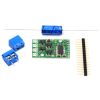
Included Hardware
A 16-pin straight breakaway male header, one 100 uF axial capacitor, and two 2-pin 5mm terminal blocks are included with each motor driver. Connecting a large capacitor across the power supply is recommended; one way to do it is between the '+' and '-' holes, as shown below. The two mounting holes are intended to be used with #2 screws (not included).
|
|


Motor Control Options
With the PWM pin held low, both motor outputs will be held low (a brake operation). With PWM high, the motor outputs will be driven according to the DIR input. This allows two modes of operation: sign-magnitude, in which the PWM duty cycle controls the speed of the motor and DIR controls the direction, and locked-antiphase, in which a pulse-width-modulated signal is applied to the DIR pin with PWM held high.
In locked-antiphase operation, a low duty cycle drives the motor in one direction, and a high duty cycle drives the motor in the other direction; a 50% duty cycle turns the motor off. A successful locked-antiphase implementation depends on the motor inductance and switching frequency smoothing out the current (e.g. making the current zero in the 50% duty cycle case), so a high PWM frequency might be required.
| Motor Driver Truth Table | ||||
|---|---|---|---|---|
| PWM | DIR | OUTA | OUTB | Operation |
| H | L | L | H | Forward |
| H | H | H | L | Backward |
| L | X | L | L | Brake |
PWM Frequency
The motor driver supports PWM frequencies as high as 40 kHz, though higher frequencies result in higher switching losses in the motor driver. Also, the driver has a dead time (when the outputs are not driven) of approximately 3 us per cycle, so high duty cycles become unavailable at high frequencies. For example, at 40 kHz, the period is 25 us; if 3 us of that is taken up by the dead time, the maximum available duty cycle is 22/25, or 88%. (100% is always available, so gradually ramping the PWM input from 0 to 100% will result in the output ramping from 0 to 88%, staying at 88% for inputs of 88% through 99%, and then switching to 100%.)
Real-World Power Dissipation Considerations
The motor driver can handle large current spikes for short durations (e.g. 100 A for a few milliseconds). The peak ratings are for quick transients (e.g. when a motor is first turned on), and the continuous rating of 12 A is dependent on various conditions, such as the ambient temperature. The actual current you can deliver will depend on how well you can keep the motor driver cool. The driver’s printed circuit board is designed to draw heat out of the MOSFETs, but performance can be improved by adding a heat sink. With a heat sink the motor driver can be run at up to 17 A of continuous current. For more information on power dissipation see the data sheet for the MOSFETs on the Resources tab.
Warning: This motor driver has no over-current or over-temperature shut-off. Either condition can cause permanent damage to the motor driver. You might consider using an external current sensor, such as Pololu's ACS714 ±30A bidirectional current sensor carrier to monitor your current draw.
Fault Conditions
The motor driver can detect three different fault states, which are reported on the FF1 and FF2 pins. The detectable faults are short circuits on the output, under-voltage, and over-temperature. A short-circuit fault is latched, meaning the outputs will stay off and the fault flag will stay high, until the board is reset (RESET brought low). The under-voltage fault disables outputs but is not latched. The over-temperature fault provides a weak indication of the board being too hot, but it does not directly indicate the temperature of the MOSFETs, which are usually the first components to overheat. The fault flag operation is summarized below.
| Flag State | Fault Description | Disable Outputs | Latched Until Reset | |
|---|---|---|---|---|
| FF1 | FF2 | |||
| L | L | No fault | No | No |
| L | H | Short Circuit | Yes | Yes |
| H | L | Over Temperature | No | No |
| H | H | Under Voltage | Yes | No |
High-Power Motor Driver Versions
There are currently nine versions of the high-power motor driver. The three CS versions have the same pinout, and the six non-CS versions have the same pinout. The following table provides a comparison of the high-power motor drivers:
| Pololu high-power motor drivers | ||
|---|---|---|
| Name | Max nominal battery voltage (V) | Max continuous current (A) w/o heat sink |
| High-power motor driver 18v25 CS | 18 | 25 |
| High-power motor driver 18v25 | 18 | 25 |
| High-power motor driver 18v15 | 18 | 15 |
| High-power motor driver 24v23 CS | 28 | 23 |
| High-power motor driver 24v20 | 28 | 20 |
| High-power motor driver 24v12 | 28 | 12 |
| High-power motor driver 36v20 CS | 36 | 20 |
| High-power motor driver 36v15 | 36 | 15 |
| High-power motor driver 36v9 | 36 | 9 |
Note: Please consider Pololu's Simple Motor Controllers as alternatives to these motor drivers. They have very similar power characteristics and offer high-level interfaces (e.g. USB, RC hobby servo pulses, analog voltages, and TTL serial commands) that make them much easier to use for many applications.
Exact shipping can be calculated on the view cart page (no login required).
Products that weigh more than 0.5 KG may cost more than what's shown (for example, test equipment, machines, >500mL liquids, etc).
We deliver Australia-wide with these options (depends on the final destination - you can get a quote on the view cart page):
- $3+ for Stamped Mail (typically 10+ business days, not tracked, only available on selected small items)
- $7+ for Standard Post (typically 6+ business days, tracked)
- $11+ for Express Post (typically 2+ business days, tracked)
- Pickup - Free! Only available to customers who live in the Newcastle region (must order online and only pickup after we email to notify you the order is ready). Orders placed after 2PM may not be ready until the following business day.
Non-metro addresses in WA, NT, SA & TAS can take 2+ days in addition to the above information.
Some batteries (such as LiPo) can't be shipped by Air. During checkout, Express Post and International Methods will not be an option if you have that type of battery in your shopping cart.
International Orders - the following rates are for New Zealand and will vary for other countries:
- $12+ for Pack and Track (3+ days, tracked)
- $16+ for Express International (2-5 days, tracked)
If you order lots of gear, the postage amount will increase based on the weight of your order.
Our physical address (here's a PDF which includes other key business details):
40 Aruma Place
Cardiff
NSW, 2285
Australia
Take a look at our customer service page if you have other questions such as "do we do purchase orders" (yes!) or "are prices GST inclusive" (yes they are!). We're here to help - get in touch with us to talk shop.
Have a product question? We're here to help!
Guides

The Maker Revolution
Projects

The Rats Nest VCC Desktop Power Supply

Remote-Controlled Mars Rover

FlipperMate: Hands-Free Pinball

Makers love reviews as much as you do, please follow this link to review the products you have purchased.
Product Comments