


Pololu H2 High-Power Motor Driver 36v11 CS
Available with a lead time
Expect dispatch between Jul 27 and Jul 29
Quantity Discounts:
- 6+ $81.34 (exc GST)
- 12+ $78.80 (exc GST)
 |
The Pololu H2 high-power motor driver 36v11 CS is a discrete MOSFET H-bridge designed to drive large brushed DC motors. The H-bridge is made up of one N-channel MOSFET per leg; the rest of the board contains the circuitry to take user inputs and control the MOSFETs. The absolute maximum voltage for this motor driver is 60 V, and higher voltages can permanently destroy the motor driver. Under normal operating conditions, ripple voltage on the supply line can raise the maximum voltage to more than the average or intended voltage, so a safe maximum voltage is approximately 48 V.
Note: Battery voltages can be much higher than nominal voltages when they are charged, so the maximum nominal battery voltage Pololu recommend is 36 V (and use with 48 V batteries is not recommended) unless appropriate measures are taken to limit the peak voltage.
The versatility of this driver makes it suitable for a large range of currents and voltages: it can deliver up to 11 A of continuous current with a board size of only 1.3" × 0.8" and no required heat sink. The module offers a simple interface that requires as few as two I/O lines, and an on-board current sensor gives a direct measurement of motor current. The power supply inputs feature reverse-voltage protection, while integrated detection of various fault conditions helps protect against other common causes of catastrophic failure; however, please note that the board does not include over-temperature protection. Pololu recommend you use the integrated current sensor to keep the driver from delivering more current than it can safely handle.
Features
- Operating voltage: 5 V to 60 V (absolute maximum)
- Maximum continuous output current: 11 A
- Inputs compatible with 3.3 V, and 5 V logic
- On-board current sensor directly measures motor current
- Reverse-voltage protection
- Undervoltage shutdown
- Short circuit protection
G2 and H2 high-power motor driver versions
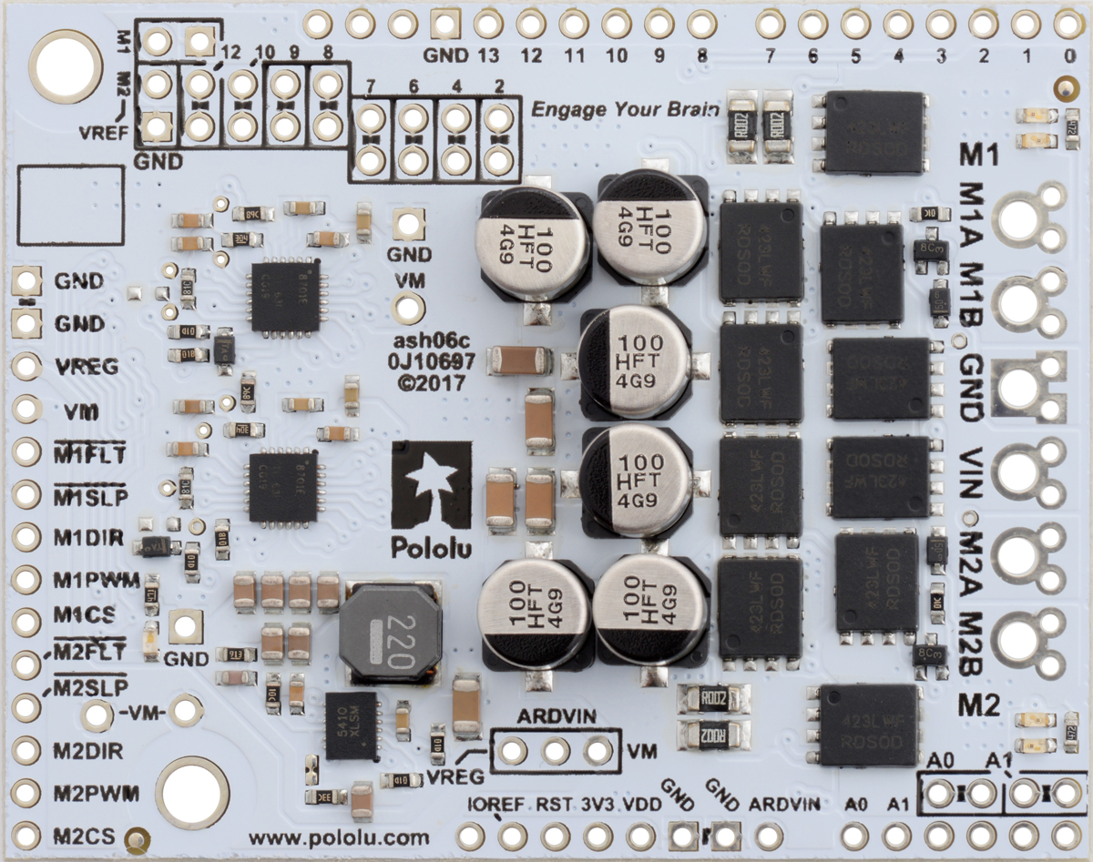
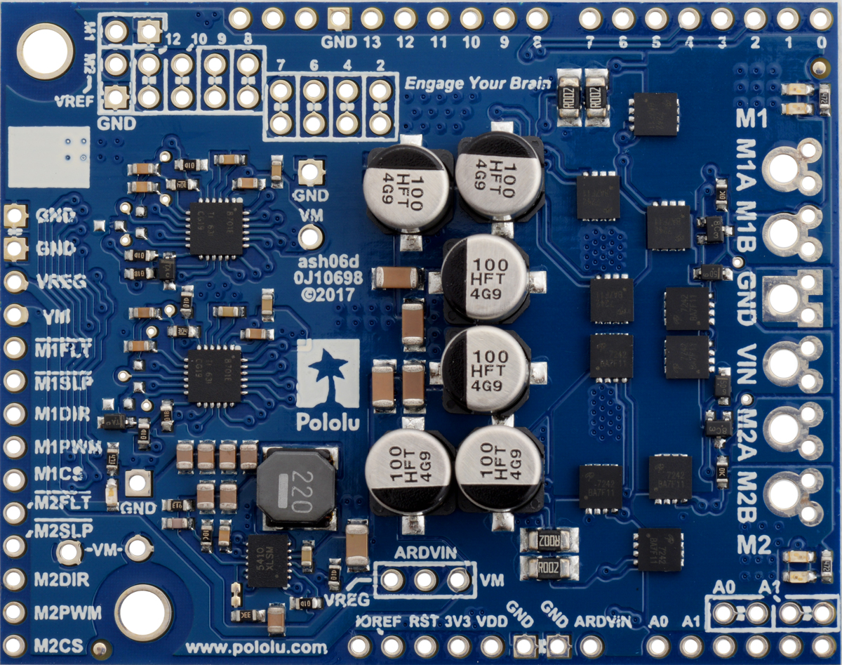
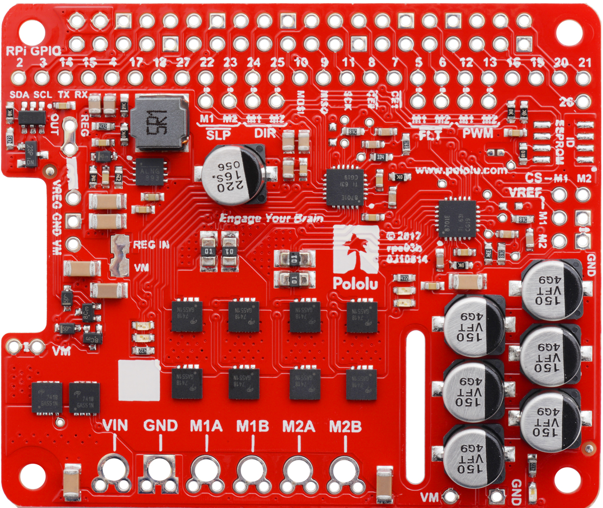
There are four versions of the single-channel G2 high-power motor drivers that share compatible pinouts, and eight versions of the dual-channel G2 high-power motor drivers. Four of the dual-channel drivers have the form factor of an Arduino shield, but they can also be used with other controllers as general-purpose motor drivers. The other four dual-channel drivers are in the form factor of a Raspberry Pi HAT and compatible Raspberry Pi boards (Model B+ or newer). Pololu also have a higher-voltage, single-channel H2 high-power motor driver with the same form factor as the single-channel G2 drivers, but the control interface and some aspects of the operation are different. The following table provides a general comparison of the G2 and H2 drivers:
| Pololu G2 High-Power Motor Drivers | |||||
|---|---|---|---|---|---|
| Motor channels | Name | Absolute max input voltage | Max nominal battery voltage | Max continuous current per channel | Default active current-limiting threshold |
| 1 | G2 High-Power Motor Driver 18v25 | 30 V | 18 V | 25 A | 60 A |
| G2 High-Power Motor Driver 18v17 | 17 A | 40 A | |||
| G2 High-Power Motor Driver 24v21 | 40 V | 28 V | 21 A | 50 A | |
| G2 High-Power Motor Driver 24v13 | 13 A | 30 A | |||
| H2 High-Power Motor Driver 36v11 CS | 60 V | 36 V | 11 A | – | |
| 2 | Dual G2 High-Power Motor Driver 18v22 Shield | 30 V | 18 V | 22 A | 60 A |
| Dual G2 High-Power Motor Driver 18v18 Shield | 18 A | 50 A | |||
| Dual G2 High-Power Motor Driver 24v18 Shield | 40 V | 28 V | 18 A | 50 A | |
| Dual G2 High-Power Motor Driver 24v14 Shield | 14 A | 40 A | |||
| Dual G2 High-Power Motor Driver 18v22 for RPi | 30 V | 18 V | 22 A | 60 A | |
| Dual G2 High-Power Motor Driver 18v18 for RPi | 18 A | 50 A | |||
| Dual G2 High-Power Motor Driver 24v18 for RPi | 40 V | 28 V | 18 A | 50 A | |
| Dual G2 High-Power Motor Driver 24v14 for RPi | 14 A | 40 A | |||
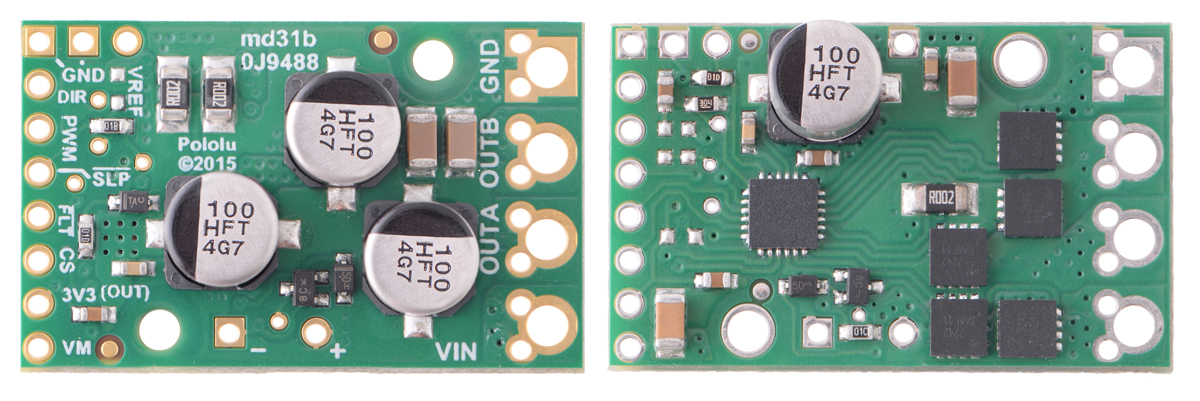 |
Pololu G2 High-Power Motor Driver 24v21 and 24v13. |
|---|
|
|
|
|
Note: As an alternative to these motor drivers, Pololu's Simple Motor Controllers have similar power characteristics and offer high-level interfaces (e.g. USB, RC hobby servo pulses, analog voltages, and TTL serial commands) that make them easier to use for some applications.
Using the motor driver
Connections
The motor and motor power connections are on one side of the board, and the control connections (3 V to 5 V logic) are on the other side. The motor supply should be capable of supplying high current. There are two options for making the high-power connections (VIN, OUTA, OUTB, GND): large holes spaced 5 mm apart, which are compatible with the included terminal blocks, and pairs of 0.1"-spaced holes that can be used with perfboards, breadboards, and 0.1" connectors.
For good performance, it is very important to install a large capacitor across the motor supply and ground close to the motor driver. Pololu generally recommend using a capacitor of at least a few hundred µF and rated well above the maximum supply voltage; the required capacitance will be greater if the power supply is poor or far (more than about a foot) from the driver, and it will also depend on other factors like motor characteristics and applied PWM frequency. A through-hole capacitor can be installed directly on the board in the holes labeled '+' and '-' (connected to VM and GND, respectively). The driver includes an on-board 22 µF capacitor, which might be sufficient for brief tests and limited low-power operation, but adding a bigger capacitor is strongly recommended for most applications.
Warning: Take proper safety precautions when using high-power electronics. Make sure you know what you are doing when using high voltages or currents! During normal operation, this product can get hot enough to burn you. Take care when handling this product or other components connected to it.
The logic connections are designed to interface with 3 V to 5 V systems (5.5 V max).
Pinout
 |
| PIN | Default State | Description |
|---|---|---|
| VIN | This is the main 5 V to 60 V (absolute max) motor power supply connection. | |
| VM | This pin gives you access to the motor power supply after reverse-voltage protection. It can be used to supply reverse-protected power to other components in the system, but it should not be used for high currents. This pin should only be used as an output. | |
| +, - | These pads are intended for a power supply capacitor (they are connected to VM and GND, respectively). | |
| VCC | 3 V to 5.5 V logic supply voltage input. Be careful not to accidentally short this pin to the neighboring VM pin while power is being supplied as doing so will instantly destroy the board! | |
| GND | Ground connection for logic and motor power supplies. | |
| OUTA | Motor output pin A (connects to one terminal of a DC motor). | |
| OUTB | Motor output pin B (connects to the other terminal of a DC motor). | |
| PWMA | LOW | Pulse width modulation input A: a PWM signal on this pin corresponds to a PWM output on OUTA. |
| PWMB | LOW | Pulse width modulation input B: a PWM signal on this pin corresponds to a PWM output on OUTB. |
| SLP | HIGH | Inverted sleep input: This pin is pulled high by the driver board, enabling the driver by default; drive SLP low to put the motor driver into a low-power sleep mode. |
| FLT | Fault indicator: This output is normally pulled up to VCC and is driven low when a fault has occurred. See below for details. | |
| CS | Current sensor output: This pin outputs a voltage proportional to the motor current. See below for details. |
Motor control
The only required control pins are PWMA and PWMB. These inputs directly control the state of the corresponding OUTA and OUTB pins, as shown in the following truth table:
| Pololu H2 High-Power Motor Driver Truth Table | ||||
|---|---|---|---|---|
| PWMA | PWMB | OUTA | OUTB | operating mode |
| 0 | 0 | L | L | brake low (outputs shorted to ground) |
| PWM | 0 | PWM (H/L) | L | forward/brake at speed PWM % |
| 0 | PWM | L | PWM (H/L) | reverse/brake at speed PWM % |
| 1 | 1 | H | H | brake high (outputs shorted to VM) |
PWM frequency
The motor driver supports PWM frequencies as high as 100 kHz, but note that switching losses in the driver will be proportional to the PWM frequency. Typically, around 20 kHz is a good choice since it is high enough to be ultrasonic, which results in quieter operation.
A high pulse on the PWM pin must be high for a minimum duration of approximately 0.25 µs before the outputs turn on for the corresponding duration (any shorter input pulse does not produce a change on the outputs), so low duty cycles become unavailable at high frequencies. For example, at 100 kHz, the pulse period is 10 µs, and the minimum non-zero duty cycle achievable is 0.25/10, or 2.5%.
Minimum off time
While the driver supports 100% duty cycle operation, any low pulse on the PWM inputs must be at least 0.3 µs long to prevent spurious, latched triggering of the short-circuit fault. This corresponds to duty cycles below 99.4% at 20 kHz or below 97% at 100 kHz. To avoid these spurious faults, Pololu recommend capping the duty cycles provided to the driver inputs at the maximum duty cycle or jumping from the maximum directly to 100% (for example, at 20 kHz, do not go above 99%, or jump from 99% to 100% if 100% operation is preferable to 99%).
Current sensor
The motor driver’s current sense pin, CS, outputs a voltage proportional to the motor current and VCC voltage. The CS voltage, VCS, is centered at VCC/2 when there is no current flowing and changes by about 90 mV/A when VCC is 3.3 V or 136 mV/A when VCC is 5 V. Current flowing from OUTA to OUTB is considered positive and increases VCS, while current flowing from OUTB to OUTA decreases VCS:
VCS=VCC2+0.090VA·VCC3.3V·IA?B=VCC·(12+IA?B36.7A)
IA?B=36.7A·(VCSVCC–12)
The total measurable current range is -15 A to +15 A. For details, see the ACS711 datasheet (533k pdf). (The version used on this driver is the ACS711KEXLT-15AB-T.)
Fault conditions
The motor driver can detect several fault states that it reports by driving the FLT pin low; this pin is otherwise pulled up to VCC. The detectable faults include short circuits on the outputs, under-voltage, and over-temperature. All of the faults disable the motor outputs and are latched, meaning the driver will remain disabled until the SLP pin is toggled or VIN (motor power) is removed and reapplied. The over-temperature fault provides a weak indication of the board being too hot, but it does not directly indicate the temperature of the MOSFETs, which are usually the first components to overheat, so you should not count on this fault to prevent damage from over-temperature conditions. Additionally, note that spurious short-circuit faults can occur if minimum off time requirements are not respected (see the Minimum off time section above).
 |
Real-world power dissipation considerations
The MOSFETs can handle large current spikes for short durations (e.g. 100 A for a few milliseconds). The peak ratings are for quick transients (e.g. when a motor is first turned on), and the continuous rating of 11 A is dependent on various conditions, such as the ambient temperature. PWMing the motor will introduce additional heating proportional to the frequency. The actual current you can deliver will depend on how well you can keep the motor driver cool. The driver’s printed circuit board is designed to draw heat out of the MOSFETs, but performance can be improved by adding a heat sink.
Warning: This motor driver has no over-current or over-temperature shut-off. Either condition can cause permanent damage to the motor driver. Pololu recommend you use the current-sense output CS to monitor your current draw if your application will put the driver close to its limits of operation.
Included hardware
|
|


Two 8-pin straight breakaway male headers and a 4-pin set of 5mm terminal blocks are included with each motor driver. Please note that the terminal blocks might come as one continuous (not separable) 4-pin piece or as two 2-pin pieces that can slide together to form a 4-pin strip. You can solder the terminal blocks to the four large through-holes to make your motor and motor power connections, or you can solder one of the 1×8 0.1" header strips into the smaller through-holes that border these larger holes. Note, however, that the terminal blocks are only rated for 16 A, and each header pin pair is only rated for a combined 6 A, so for higher-power applications, thick wires should be soldered directly to the board.
The other 1×8 header strip can be soldered into the small holes on the logic connection side of the board to enable use with solderless breadboards, perfboards, or 0.1" connectors, or you can solder wires directly to these holes for the most compact installation.
Note: In most applications, it is necessary to connect an additional large capacitor (not included) across the power supply, as described under the Connections section above.
The board has two 0.086" (2.18 mm) diameter mounting holes intended for #2 or M2 screws (not included); they are separated by 0.62" (15.75 mm) both horizontally and vertically.
Differences from original and G2 high-power motor drivers
The H2 high-power motor driver is designed to work as a near drop-in replacement for Pololu's original high-power motor drivers and G2 high-power motor drivers; this version, the 36v11 CS, is comparable to the original 36v9 but can generally provide higher output currents. The overall board dimensions and locations of the mounting holes are the same for both versions, as are the locations of most of the required pins.
Compared to the original, this second-generation driver adds new features including a wider motor voltage range, reverse-voltage protection on the power supply inputs, and current sensing functionality. It also works with lower logic voltages, making it compatible with 3.3 V systems.
The pinout of the H2 driver differs from the original and G2 drivers in several ways:
- The H2 driver has two PWM inputs that directly control the state of the corresponding motor outputs, unlike the original and G2 drivers, which have a speed/direction interface.
- The H2 driver has only one fault pin, which is a normally high output that is driven low when a fault occurs. (The original driver had two fault pins that were driven high to indicate faults, and the G2 drivers have an open-drain fault pin.)
- A current sense output is available on the G2 driver in place of the second fault pin. Unlike the G2 drivers’ current sense output, which is only active while the H-bridge is driving, the H2 driver has a dedicated current sensor that measures the actual motor current at all times.
- The H2 driver does not have the current limiting functionality of the G2 drivers.
- The H2 driver’s VCC pin is a logic voltage input that must be supplied with 3 V to 5.5 V (the original and G2 drivers provide a 5 V or 3.3 V output respectively).
Dimensions
| Size: | 1.3" × 0.8" |
|---|---|
| Weight: | 3.3 g1 |
General specifications
| Motor channels: | 1 |
|---|---|
| Minimum operating voltage: | 5 V |
| Maximum operating voltage: | 60 V2 |
| Continuous output current per channel: | 11 A3 |
| Current sense: | 0.136 V/A4 |
| Minimum logic voltage: | 3.0 V |
| Maximum logic voltage: | 5.5 V |
| Minimum off time: | 300 ns5 |
| Reverse voltage protection?: | Y |
Identifying markings
| PCB dev codes: | md45a |
|---|---|
| Other PCB markings: | 0J14742, blank white box |
Notes:
- 1
- Without included connectors.
- 2
- Absolute maximum; higher voltages can permanently destroy the motor driver. Recommended maximum is approximately 48 V, which leaves a safety margin for ripple voltage on the supply line. Not recommended for use with 48V batteries.
- 3
- Typical results with 100% duty cycle at room temperature.
- 4
- When Vcc = 5 V. Sensitivity is proportional to Vcc.
- 5
- Minimum required for operation below 100% duty cycle; shorter off times can trigger spurious short circuit faults.
File downloads
-
Dimension diagram of the Pololu High-Power Motor driver 36v11 CS (312k pdf)
-
3D model of the Pololu H2 High-Power Motor Driver 36v11 CS (6MB step)
-
Drill guide for the Pololu H2 High-Power Motor Driver 36v11 CS (23k dxf)
This DXF drawing shows the locations of all of the board’s holes.
-
Allegro ACS711 current sensor datasheet (533k pdf)
This product is listed in:
Breakouts & Modules>Motor Drivers & Controllers>Brushed DC Motor ControllersExact shipping can be calculated on the view cart page (no login required).
Products that weigh more than 0.5 KG may cost more than what's shown (for example, test equipment, machines, >500mL liquids, etc).
We deliver Australia-wide with these options (depends on the final destination - you can get a quote on the view cart page):
- $3+ for Stamped Mail (typically 10+ business days, not tracked, only available on selected small items)
- $7+ for Standard Post (typically 6+ business days, tracked)
- $11+ for Express Post (typically 2+ business days, tracked)
- Pickup - Free! Only available to customers who live in the Newcastle region (must order online and only pickup after we email to notify you the order is ready). Orders placed after 2PM may not be ready until the following business day.
Non-metro addresses in WA, NT, SA & TAS can take 2+ days in addition to the above information.
Some batteries (such as LiPo) can't be shipped by Air. During checkout, Express Post and International Methods will not be an option if you have that type of battery in your shopping cart.
International Orders - the following rates are for New Zealand and will vary for other countries:
- $12+ for Pack and Track (3+ days, tracked)
- $16+ for Express International (2-5 days, tracked)
If you order lots of gear, the postage amount will increase based on the weight of your order.
Our physical address (here's a PDF which includes other key business details):
40 Aruma Place
Cardiff
NSW, 2285
Australia
Take a look at our customer service page if you have other questions such as "do we do purchase orders" (yes!) or "are prices GST inclusive" (yes they are!). We're here to help - get in touch with us to talk shop.
Have a product question? We're here to help!
 USB LiIon/LiPoly charger - v1.2SKU: ADA259 Brand: AdafruitThis is a Lithium Ion and Lithium Polymer battery charger based on the MCP73833. ...
- ADS1115 16-Bit ADC - 4 Channel with Programmable Gain AmplifierSKU: ADA1085 Brand: AdafruitFor microcontrollers without an analog-to-digital converter or when you want a h ...
- Adafruit Micro Lipo - USB LiIon/LiPoly charger - v1SKU: ADA1304 Brand: AdafruitOh so adorable, this is the tiniest little lipo charger, so handy you can keep i ...
- Adafruit Audio FX Sound Board - WAV/OGG Trigger with 16MB FlashSKU: ADA2220 Brand: AdafruitWould you like to add audio/sound effects to your next project, without an Ardui ...


Videos
View AllGuides

The Maker Revolution

Motor Drivers vs. Motor Controllers
Projects

Racing Simulator Motion Platform

Makers love reviews as much as you do, please follow this link to review the products you have purchased.
Product Comments