


Pololu Dual G2 High-Power Motor Driver 24v14 Shield for Arduino
Available with a lead time
Expect dispatch between Aug 04 and Aug 07
Quantity Discounts:
- 5+ $113.41 (exc GST)
- 10+ $109.86 (exc GST)
 |
The G2 family of dual high-power motor driver shields features pairs of discrete MOSFET H-bridges designed to drive two large brushed DC motors. They have the form factor of an Arduino shield, so Pololu can plug directly into an Arduino or compatible board, such as the A-Star 32U4 Prime, but they also break out all of the motor driver pins along the left side of the board to enable use as a general-purpose motor driver without an Arduino. Four versions are available so you can pick the one with the appropriate operating voltage range and output current capabilities for your project:
 Dual G2 High- Power Motor Driver 18v22 Shield |  Dual G2 High- Power Motor Driver 18v18 Shield |  Dual G2 High- Power Motor Driver 24v18 Shield |  Dual G2 High- Power Motor Driver 24v14 Shield | |
|---|---|---|---|---|
| Absolute max input voltage: | 30 V | 40 V | ||
| Max nominal battery voltage: | 18 V | 28 V | ||
| Max continuous current per channel: | 22 A | 18 A | 18 A | 14 A |
| Default active current- limiting threshold: | 60 A | 50 A | 40 A | |
| Current sense output: | 10 mV/A | 20 mV/A | ||
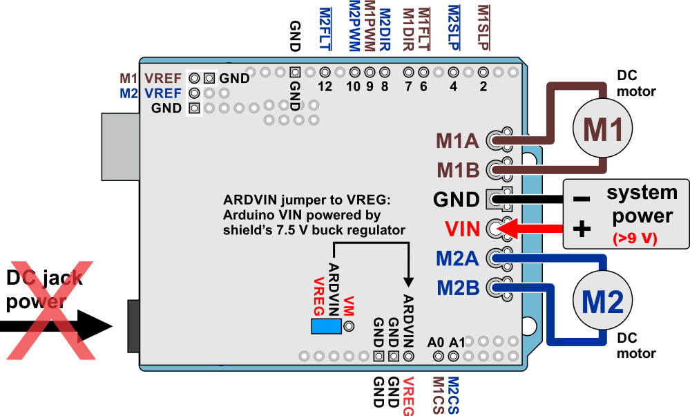
The minimum operating voltage for all four versions is 6.5 V. The maximum operating voltages are given in the above table; they are well above what typical Arduinos can tolerate, so the shields include an integrated 7.5 V, 1 A switching step-down regulator that can optionally be used to power whatever Arduino or Arduino-compatible board it is plugged into, enabling operation from a single power supply. This regulator can also be configured to output 5 V for applications where that would be more useful than the default 7.5 V, and the Arduino pin mappings can all be customized if the defaults are not convenient.
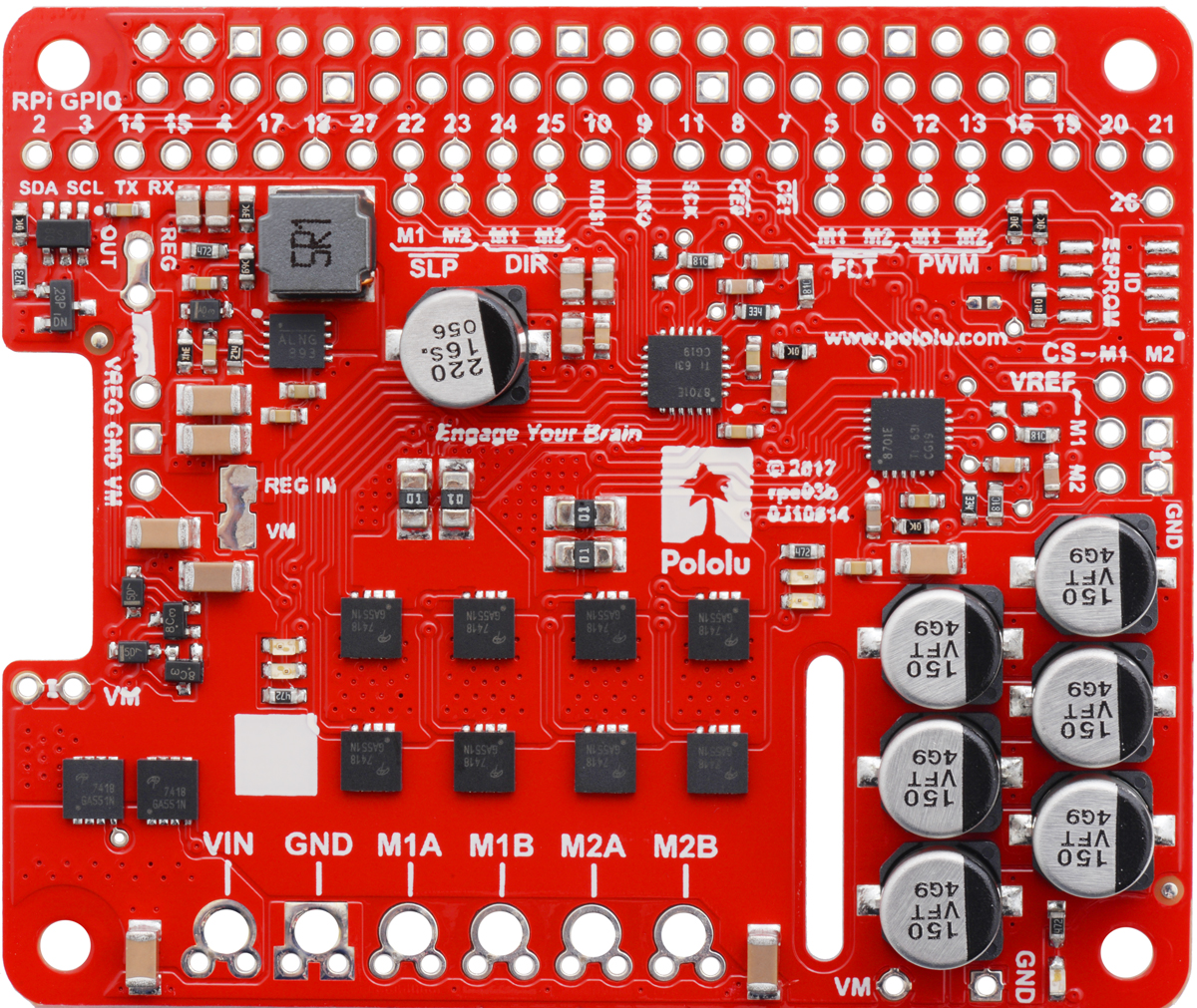
These dual motor drivers are also available as Raspberry Pi expansion boards. For single-channel versions in a more compact form factor, consider Pololu's High-Power Motor Drivers. For a lower-power, lower-cost alternative Arduino shield, please consider the Dual MC33926 Motor Driver Shield.
Details for item #2516
|
|
|

- Operating voltage: 6.5 V to 40 V (absolute maximum; not intended for use with 36 V batteries)
- Output current: 14 A continuous
- Current sense output proportional to motor current (approx. 20 mV/A; only active while H-bridge is driving)
- Active current limiting (chopping) with approximate default threshold of 40 A (can be adjusted lower)
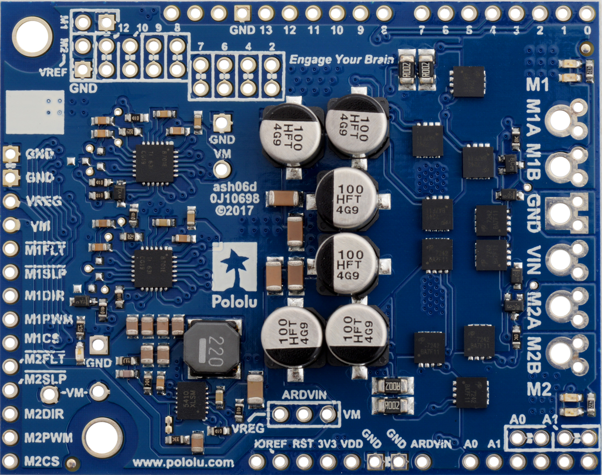
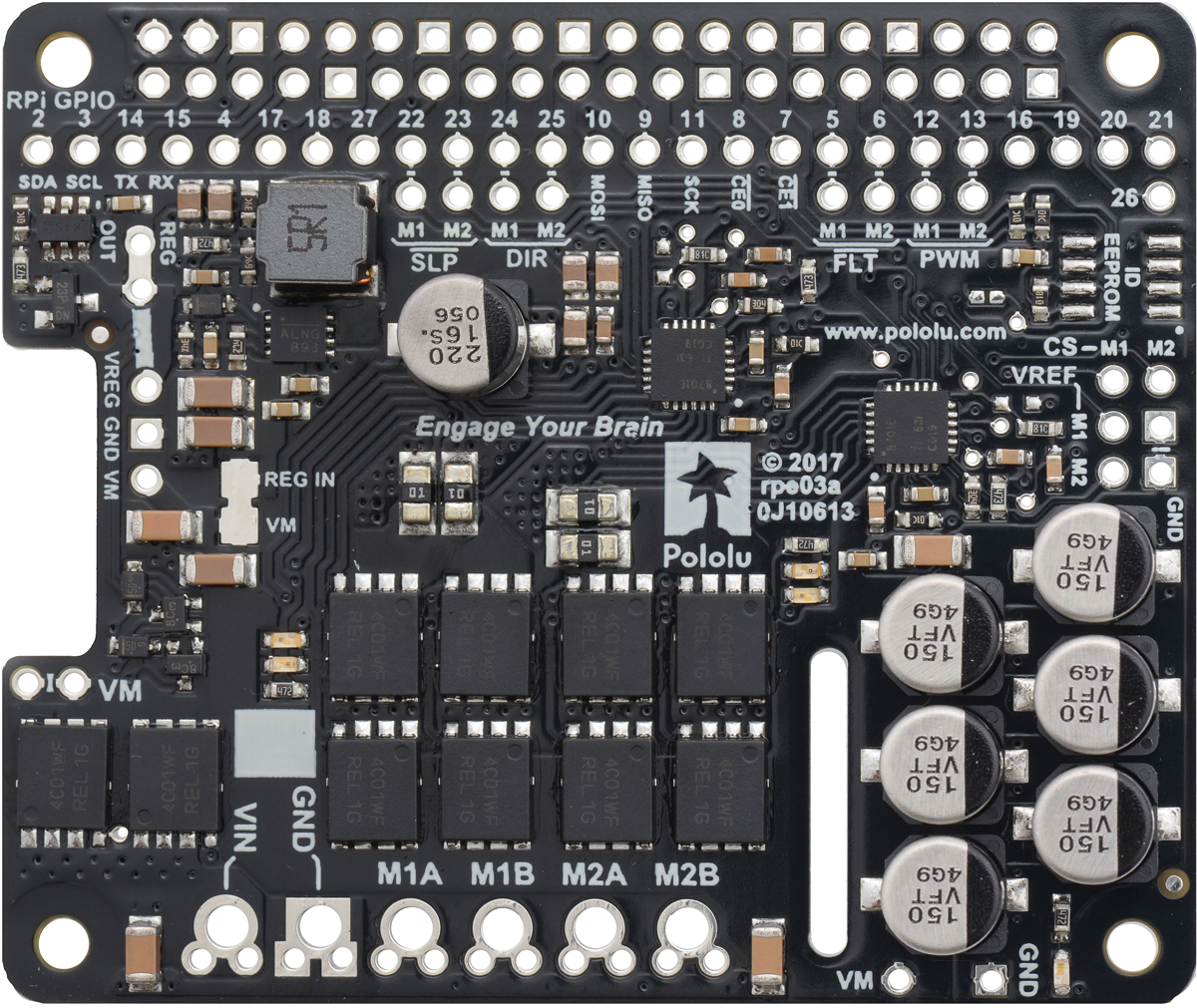
This version, the 24v14 motor driver shield, can be distinguished from the other versions by its blue PCB and the number 100 on top of the tall silver electrolytic capacitors.
Features common to all versions
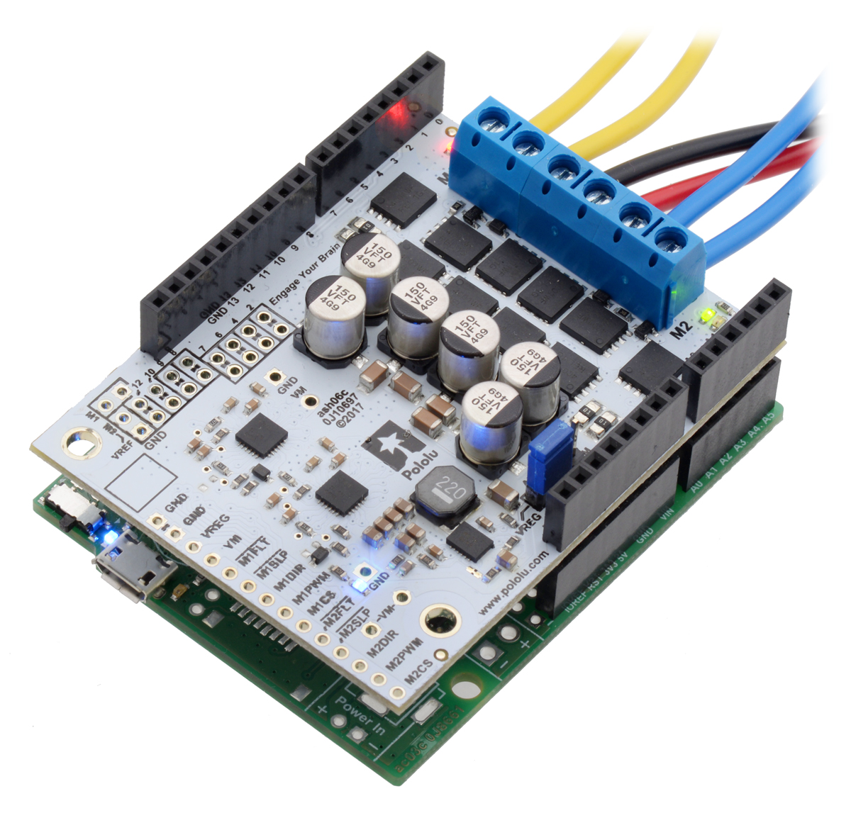 |
Pololu Dual G2 High-Power Motor Driver Shield being controlled by an A-Star 32U4 Prime. |
|---|
- Inputs compatible with 1.8 V, 3.3 V, and 5 V logic
- PWM operation up to 100 kHz
- Motor indicator LEDs show what the outputs are doing even when no motor is connected
- Reverse-voltage protection
- Undervoltage shutdown
- Short circuit protection
- Control interface allows for sign-magnitude or locked-antiphase operation
- Integrated 7.5 V, 1 A switching step-down voltage regulator (can be set to output 5 V instead)
- Arduino library makes it easy to get started using this board as a motor driver shield
- Detailed user’s guide
- Arduino pin mappings can be customized if the default mappings are not convenient
- When used as a shield, the motor power supply or 7.5 V regulator output can optionally be used to power the Arduino base for single-supply operation
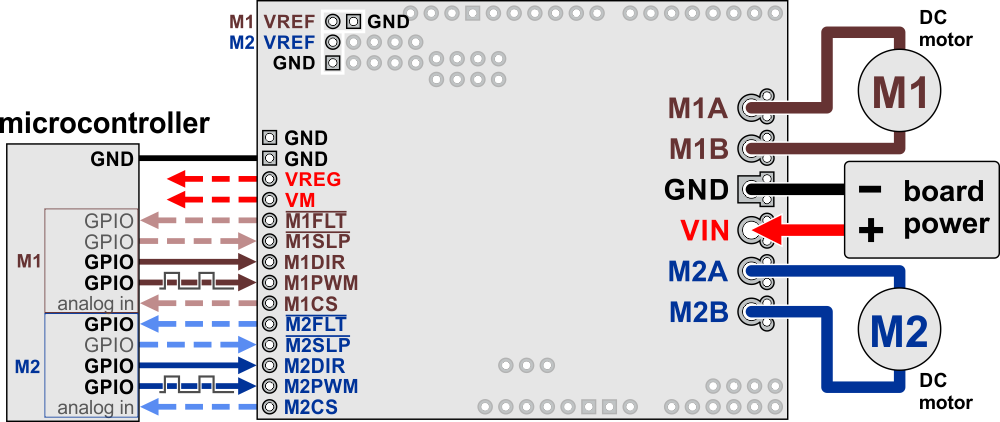
- Can be used with an Arduino or compatible board (through shield headers) or other microcontroller boards (through 0.1" header along the left side)
|
|
Included hardware
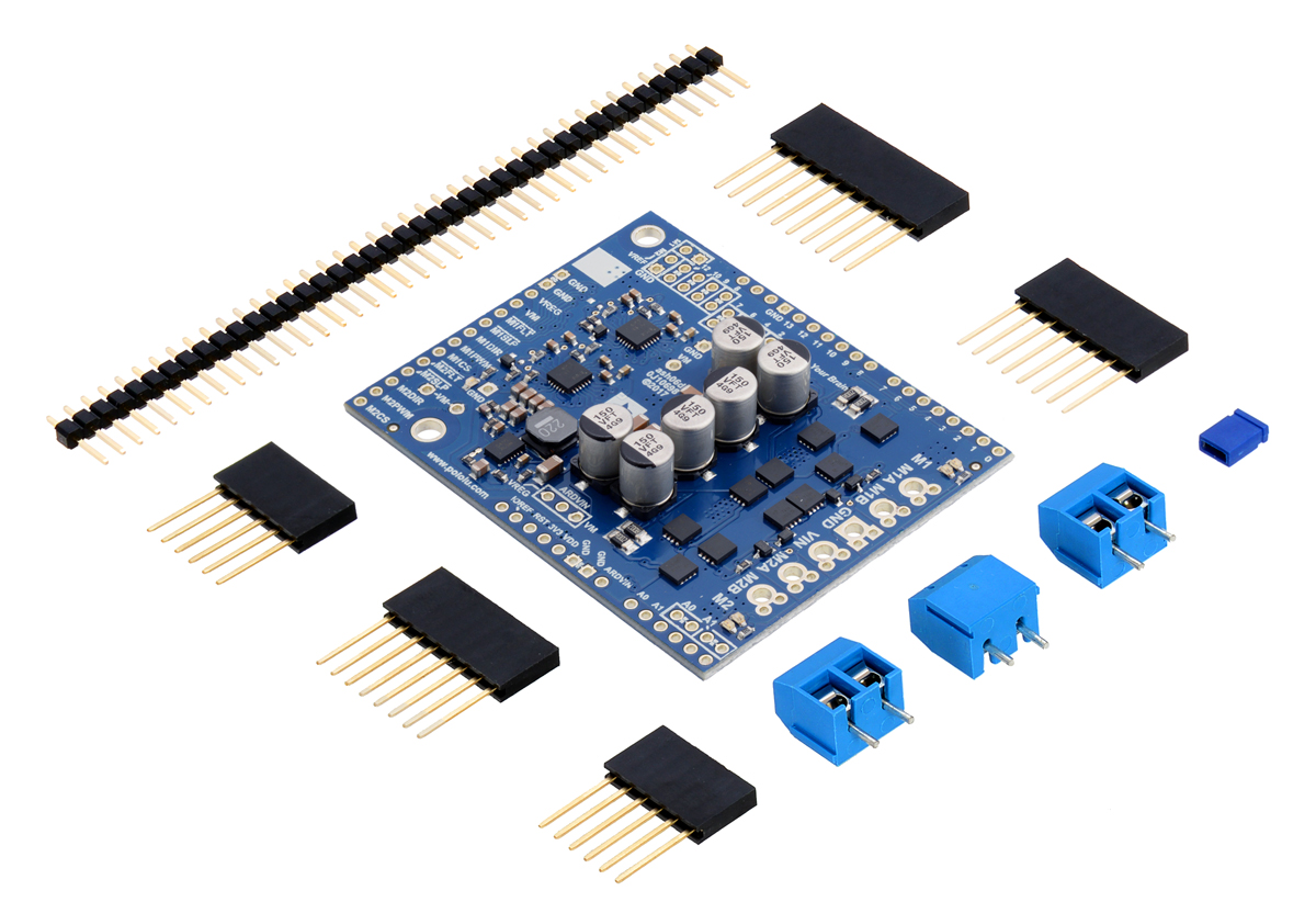 |
Pololu Dual G2 High-Power Motor Driver 18v18 Shield for Arduino with included hardware. |
|---|
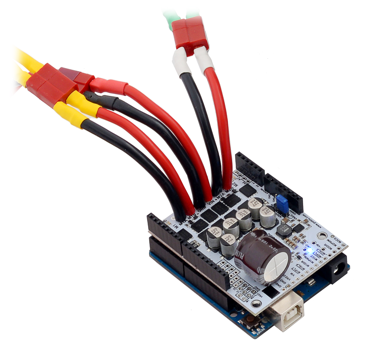 |
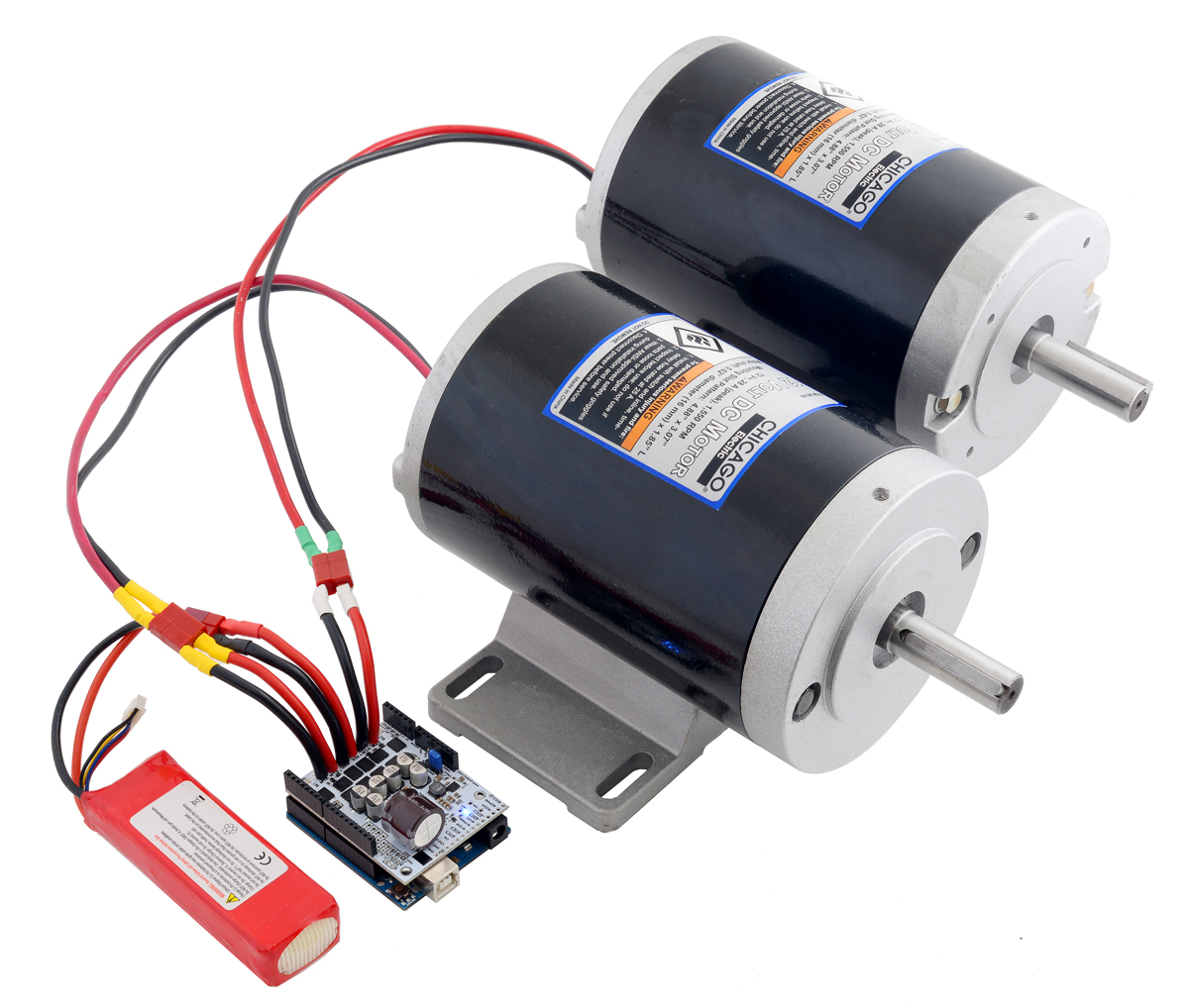
For high-current installations, motor and power supply wires should be soldered directly to the driver (the supplied terminal blocks are only rated for up to 16 A). |
|---|
This motor driver board ships with all of the surface-mount parts populated. However, soldering is required for assembly of the included through-hole parts. The following through-hole parts are included:
- one extended/stackable 1×10 female header (for Arduino shields)
- two extended/stackable 1×8 female headers (for Arduino shields)
- two extended/stackable 1×6 female headers (for Arduino shields)
- three 2-pin 5mm terminal blocks (for board power and motor outputs)
- 40-pin 0.1" straight breakaway male header (may ship in several pieces, such as two 20-pin strips)
A 0.1" shorting block (for optionally supplying shield power to Arduino) is also included.
You can solder the terminal blocks to the six large through-holes to make your motor and motor power connections, or you can break off a 1×12 section of the 0.1" header strip and solder it into the smaller through-holes that border these larger holes. Note, however, that the terminal blocks are only rated for 16 A, and each header pin pair is only rated for a combined 6 A, so for higher-power applications, thick wires should be soldered directly to the board, and appropriately high-current connectors (like these) should be used.
When not using this board as an Arduino shield, you can solder the 0.1" headers to the logic connections along the left side of the board to enable use with custom cables or solderless breadboards, or you can solder wires directly to the board for more compact installations. Note that motor and motor power connections should not be made through a breadboard.
The motor driver includes six 100 µF or 150 µF electrolytic power capacitors, and there is room to add additional capacitors (e.g. to compensate for long power wires or increase stability of the power supply). Additional power capacitors are usually not necessary, and no additional capacitors are included with this motor driver.
The two mounting holes are intended for use with #4 screws (not included).
Current sensing and limiting
The driver’s current sense pins, M1CS and M2CS, output voltages proportional to the motor currents while the H-bridge is driving. The output voltage is about 10 mV/A for the 18v22 version and 20 mV/A for the other versions, plus a small offset, which is typically about 50 mV.
The driver has the ability to limit the motor current through current chopping: once the motor drive current reaches a set threshold, the driver goes into brake mode (slow decay) for about 25 µs before applying power to drive the motor again. This makes it more practical to use the driver with a motor that might only draw a few amps while running but can draw many times that amount (tens of amps) when starting. You can lower the default current limit threshold by connecting an additional resistor between the VREF pin and the adjacent GND pin.
See the user’s guide for more information on current sense feedback and current limiting.
Real-world power dissipation consideration
The MOSFETs can handle large current spikes for short durations (e.g. 100 A for a few milliseconds), and the driver’s current chopping will keep the average current under the set limit. The peak ratings are for quick transients (e.g. when a motor is first turned on), and the continuous rating is dependent on various conditions, such as the ambient temperature. PWMing the motor will introduce additional heating proportional to the frequency. The actual current you can deliver will depend on how well you can keep the motor driver cool. The driver’s printed circuit board is designed to draw heat out of the MOSFETs, but performance can be improved by adding a heat sink or air flow. For high-current installations, the motor and power supply wires should also be soldered directly instead of going through the supplied terminal blocks, which are rated for up to 16 A.
Warning: This motor driver has no over-temperature shut-off. An over-temperature or over-current condition can cause permanent damage to the motor driver. You might consider using either the driver’s integrated current sense output or an external current sensor to monitor your current draw.
This product can get hot enough to burn under normal operating conditions. Take care when handling this product and other components connected to it.
G2 high-power motor driver versions
There are four versions of the single-channel G2 high-power motor drivers that share compatible pinouts, and eight versions of the dual-channel G2 high-power motor drivers. Four of the dual-channel drivers have the form factor of an Arduino shield, but they can also be used with other controllers as general-purpose motor drivers. The other four dual-channel drivers are in the form factor of a Raspberry Pi HAT and compatible Raspberry Pi boards (Model B+ or newer). The following table provides a comparison of the G2 drivers:
| Pololu G2 High-Power Motor Drivers | |||||
|---|---|---|---|---|---|
| Motor channels | Name | Absolute max input voltage | Max nominal battery voltage | Max continuous current per channel | Default active current-limiting threshold |
| 1 | G2 High-Power Motor Driver 18v25 | 30 V | 18 V | 25 A | 60 A |
| G2 High-Power Motor Driver 18v17 | 17 A | 40 A | |||
| G2 High-Power Motor Driver 24v21 | 40 V | 28 V | 21 A | 50 A | |
| G2 High-Power Motor Driver 24v13 | 13 A | 30 A | |||
| 2 | Dual G2 High-Power Motor Driver 18v22 Shield | 30 V | 18 V | 22 A | 60 A |
| Dual G2 High-Power Motor Driver 18v18 Shield | 18 A | 50 A | |||
| Dual G2 High-Power Motor Driver 24v18 Shield | 40 V | 28 V | 18 A | 50 A | |
| Dual G2 High-Power Motor Driver 24v14 Shield | 14 A | 40 A | |||
| Dual G2 High-Power Motor Driver 18v22 for RPi | 30 V | 18 V | 22 A | 60 A | |
| Dual G2 High-Power Motor Driver 18v18 for RPi | 18 A | 50 A | |||
| Dual G2 High-Power Motor Driver 24v18 for RPi | 40 V | 28 V | 18 A | 50 A | |
| Dual G2 High-Power Motor Driver 24v14 for RPi | 14 A | 40 A | |||
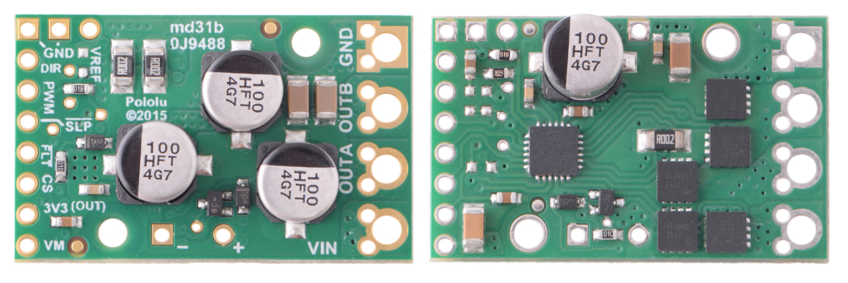 |
Pololu G2 High-Power Motor Driver 24v21 and 24v13. |
|---|
|
|
|
|
Note: As an alternative to these motor drivers, Pololu's Simple Motor Controllers have similar power characteristics and offer high-level interfaces (e.g. USB, RC hobby servo pulses, analog voltages, and TTL serial commands) that make them easier to use for some applications.
Dimensions
| Size: | 2.56" × 2.02" × 0.38"1 |
|---|---|
| Weight: | 18 g1 |
General specifications
| Motor channels: | 2 |
|---|---|
| Minimum operating voltage: | 6.5 V |
| Maximum operating voltage: | 40 V2 |
| Continuous output current per channel: | 14 A3 |
| Current sense: | 0.020 V/A |
| Maximum PWM frequency: | 100 kHz |
| Minimum logic voltage: | 1.8 V |
| Maximum logic voltage: | 5.5 V |
| Reverse voltage protection?: | Y |
Identifying markings
| PCB dev codes: | ash06d |
|---|---|
| Other PCB markings: | 0J10698, blank white box |
Notes:
- 1
- Without included hardware.
- 2
- Absolute maximum; higher voltages can permanently destroy the motor driver. Recommended maximum is approximately 34 V, which leaves a safety margin for ripple voltage on the supply line.
- 3
- Typical results at room temperature with both channels running at 90% duty cycle.
Documentation and other information
-

Pololu Dual G2 High-Power Motor Driver Shields for Arduino User’s Guide
User’s manual for the Pololu Dual G2 High-Power Motor Driver Shields for Arduino.

File downloads
-
Dimension diagram of the Pololu Dual G2 High-Power Motor Driver 18v18 or 24v14 Shield for Arduino (261k pdf)
-
Dimension diagram of the Pololu Dual G2 High-Power Motor Driver 18v22 or 24v18 Shield for Arduino (271k pdf)
-
3D model of the Dual G2 High-Power Motor Driver 18v18 or 24v14 Shield for Arduino (12MB step)
-
3D model of the Dual G2 High-Power Motor Driver 18v22 or 24v18 Shield for Arduino (10MB step)
-
Drill guide for the Dual G2 High-Power Motor Driver 18v22 or 24v18 Shield for Arduino (166k dxf)
This DXF drawing shows the locations of all of the board’s holes.
-
Drill guide for the Dual G2 High-Power Motor Driver 18v18 or 24v14 Shield for Arduino (166k dxf)
This DXF drawing shows the locations of all of the board’s holes.
Recommended links
-
Arduino library for the Pololu Dual G2 High Power Motor Driver Shields
This library for the Arduino makes it easy to interface with Pololu’s Dual G2 High-Power Motor Driver Shields and drive a pair of high-power, brushed DC motors. A sample sketch is included with the library.
Exact shipping can be calculated on the view cart page (no login required).
Products that weigh more than 0.5 KG may cost more than what's shown (for example, test equipment, machines, >500mL liquids, etc).
We deliver Australia-wide with these options (depends on the final destination - you can get a quote on the view cart page):
- $3+ for Stamped Mail (typically 10+ business days, not tracked, only available on selected small items)
- $7+ for Standard Post (typically 6+ business days, tracked)
- $11+ for Express Post (typically 2+ business days, tracked)
- Pickup - Free! Only available to customers who live in the Newcastle region (must order online and only pickup after we email to notify you the order is ready). Orders placed after 2PM may not be ready until the following business day.
Non-metro addresses in WA, NT, SA & TAS can take 2+ days in addition to the above information.
Some batteries (such as LiPo) can't be shipped by Air. During checkout, Express Post and International Methods will not be an option if you have that type of battery in your shopping cart.
International Orders - the following rates are for New Zealand and will vary for other countries:
- $12+ for Pack and Track (3+ days, tracked)
- $16+ for Express International (2-5 days, tracked)
If you order lots of gear, the postage amount will increase based on the weight of your order.
Our physical address (here's a PDF which includes other key business details):
40 Aruma Place
Cardiff
NSW, 2285
Australia
Take a look at our customer service page if you have other questions such as "do we do purchase orders" (yes!) or "are prices GST inclusive" (yes they are!). We're here to help - get in touch with us to talk shop.
Have a product question? We're here to help!
- ADS1115 16-Bit ADC - 4 Channel with Programmable Gain AmplifierSKU: ADA1085 Brand: AdafruitFor microcontrollers without an analog-to-digital converter or when you want a h ...
- Adafruit Micro Lipo - USB LiIon/LiPoly charger - v1SKU: ADA1304 Brand: AdafruitOh so adorable, this is the tiniest little lipo charger, so handy you can keep i ...
- Adafruit Audio FX Sound Board - WAV/OGG Trigger with 16MB FlashSKU: ADA2220 Brand: AdafruitWould you like to add audio/sound effects to your next project, without an Ardui ...
- Adafruit Mono 2.5W Class D Audio Amplifier - PAM8302SKU: ADA2130 Brand: AdafruitThis super small mono amplifier is surprisingly powerful - able to deliver up to ...


Guides

The Maker Revolution
Projects

The Rats Nest VCC Desktop Power Supply

Remote-Controlled Mars Rover

FlipperMate: Hands-Free Pinball

Makers love reviews as much as you do, please follow this link to review the products you have purchased.
Product Comments