
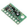


LPS25HB Pressure/Altitude Sensor Carrier with Voltage Regulator
Quantity Discounts:
- 10+ $14.45 (exc GST)
- 25+ $13.99 (exc GST)
Out of Stock
Sign up to get notified when it's available to order.
 |
This board is a compact (0.4" × 0.8") carrier for ST’s LPS25HB MEMS absolute pressure sensor, or barometer; Pololu therefore recommend careful reading of the LPS25HB datasheet (2MB pdf) before using this product. The LPS25HB is a great IC, but its small, leadless, LGA package makes it difficult for the typical student or hobbyist to use. It also operates at voltages below 3.6 V, which can make interfacing difficult for microcontrollers operating at 5 V. This carrier board addresses these issues by incorporating additional electronics, including a 3.3 V voltage regulator and level-shifting circuits, while keeping the overall size as compact as possible. The board ships fully populated with its SMD components, including the LPS25HB, as shown in the product picture.
The LPS25HB is a drop-in replacement for the earlier LPS25H that offers improved reliability and moisture resistance. It otherwise offers the same performance and presents the same register map, so no design changes are required when moving from the LPS25H to the LPS25HB. Compared to the earlier LPS331AP, the LPS25HB features improved accuracy and reduced noise in the output. The addition of a built-in FIFO (First In, First Out) buffer allows the sensor to store pressure readings for burst transmission, reducing overall power consumption by allowing the host processor to sleep longer between data requests. Alternatively, the FIFO can be configured to perform a running average of pressure readings to further decrease the output noise.
This LPS25HB carrier board is pin-compatible with Pololu's LPS331AP carrier, but due to the removal of one of the interrupt pins on the LPS25HB, the position of the mounting hole has changed relative to the remaining pins. The two sensors use the same I²C addresses, but some of their configuration register fields are different, so code written to interface with an LPS331 might need to be modified to work with an LPS25HB.
The LPS25HB features embedded temperature compensation and has many configurable options, including selectable resolutions, a choice of output data rates, several FIFO operating modes, and a programmable external interrupt signal. Its pressure output has an absolute pressure accuracy over temperature as low as ±0.2 mbar (0.02 kPa), with RMS noise of 0.01 mbar (0.001 kPa) in the highest-resolution mode with embedded filtering enabled. Pressure and temperature sensor data are available through a digital interface, which can be configured to operate in either I²C or SPI mode, and can be used for altimetry. (See the Sample Code section below for an Arduino library that can be used to turn this sensor into an altimeter.)
The carrier board includes a low-dropout linear voltage regulator that provides the 3.3 V required by the LPS25HB, which allows the sensor to be powered from a 2.5 V to 5.5 V supply. The regulator output is available on the VDD pin and can supply almost 150 mA to external devices. The breakout board also includes a circuit that shifts the I²C/SPI clock and data in lines to the same logic voltage level as the supplied VIN, making it simple to interface the board with 5 V systems, and the board’s 0.1" pin spacing makes it easy to use with standard solderless breadboards and 0.1" perfboards.
Specifications
- Dimensions: 0.4" × 0.8" × 0.1" (10 mm × 20 mm × 3 mm)
- Weight without header pins: 0.5 g (0.02 oz)
- Operating voltage: 2.5 V to 5.5 V
- Supply current: 2 mA
- Output format (I²C/SPI): 24-bit pressure reading (4096 LSb/mbar)
- Sensitivity range: 260 mbar to 1260 mbar (26 kPa to 126 kPa)
Included components
A 1×8 strip of 0.1" header pins and a 1×8 strip of 0.1" right-angle header pins are included, as shown in the picture below. You can solder the header strip of your choice to the board for use with custom cables or solderless breadboards, or you can solder wires directly to the board itself for more compact installations.
 |
The board has one mounting hole that works with #2 and M2 screws (not included).
Using the LPS25HB
Connections
Regardless of the interface being used to communicate with the LPS25HB, its VIN pin should be connected to a 2.5 V to 5.5 V source, and GND should be connected to 0 volts. (Alternatively, if you are using the sensor with a 3.3 V system, you can leave VIN disconnected and bypass the built-in regulator by connecting 3.3 V directly to VDD.)
A minimum of two logic connections are necessary to use the LPS25HB in I²C mode (this is the default mode): SCL and SDA. These pins are connected to built-in level-shifters that make them safe to use at voltages over 3.3 V; they should be connected to an I²C bus operating at the same logic level as VIN. The remaining pins are not connected to level-shifters on the board and are not 5V-tolerant, but Pololu's 4-channel bidirectional logic level shifter can be used externally with those pins to achieve the same effect.
To use the LPS25HB in the default SPI mode, four logic connections are required: SPC, SDI, SDO, and CS. These should be connected to an SPI bus operating at the same logic level as VIN. The SPI interface operates in 4-wire mode by default, with SDI and SDO on separate pins, but it can be configured to use 3-wire mode so that SDO shares a pin with SDI.
|

Pinout
| PIN | Description |
|---|---|
| VDD | Regulated 3.3 V output. Almost 150 mA is available to power external components. (If you want to bypass the internal regulator, you can instead use this pin as a 3.3 V input with VIN disconnected.) |
| VIN | This is the main 2.5 V to 5.5 V power supply connection. The SCL/SPC and SDA/SDI level shifters pull the I²C and SPI bus high bits up to this level. |
| GND | The ground (0 V) connection for your power supply. Your I²C or SPI control source must also share a common ground with this board. |
| SDA/SDI/SDO | Level-shifted I²C data line and SPI data in line (also doubles as SDO in 3-wire mode): HIGH is VIN, LOW is 0 V |
| SCL/SPC | Level-shifted I²C/SPI clock line: HIGH is VIN, LOW is 0 V |
| SDO/SA0 | SPI data out line in 4-wire mode: HIGH is VDD, LOW is 0 V. This output is not level-shifted. Also used as an input to determine I²C slave address (see below). |
| CS | SPI enable (chip select). Pulled up to VDD to enable I²C communication by default; drive low to begin SPI communication. |
| INT1_DRDY | Programmable interrupt/data-ready indicator, a 3.3-V-logic-level output. This output is not level-shifted. |
Schematic diagram
 |
The above schematic shows the additional components the carrier board incorporates to make the LPS25HB easier to use, including the voltage regulator that allows the board to be powered from a 2.5 V to 5.5 V supply and the level-shifter circuit that allows for I²C and SPI communication at the same logic voltage level as VIN. This schematic is also available as a downloadable PDF (71k pdf).
I²C communication
With the CS pin in its default state (pulled up to VDD), the LPS25HB can be configured and its pressure reading can be queried through the I²C bus. Level shifters on the I²C clock (SCL) and data (SDA) lines enable I²C communication with microcontrollers operating at the same voltage as VIN (2.5 V to 5.5 V). A detailed explanation of the I²C interface on the LPS25HB can be found in its datasheet (2MB pdf), and more detailed information about I²C in general can be found in NXP’s I²C-bus specification (1MB pdf).
In I²C mode, the sensor’s 7-bit slave address has its least significant bit (LSb) determined by the voltage on the SA0 pin. The carrier board pulls SA0 to VDD through a 10 kO resistor, making the LSb 1 and setting the slave address to 1011101b by default. If the pressure sensor’s selected slave address happens to conflict with some other device on your I²C bus, you can drive SA0 low to set the LSb to 0.
The I²C interface on the LPS25HB is compliant with the I²C fast mode (400 kHz) standard. In Pololu's tests of the board, Pololu were able to communicate with the chip at clock frequencies up to 400 kHz; higher frequencies might work but were not tested.
SPI communication
To communicate with the LPS25HB in SPI mode, the CS pin (which the board pulls to VDD through a 10 kO resistor) must be driven low before the start of an SPI command and allowed to return high after the end of the command. Level shifters on the SPI clock (SPC) and data in (SDI) lines enable SPI communication with microcontrollers operating at the same voltage as VIN (2.5 V to 5.5 V).
In the default 4-wire mode, the pressure sensor transmits data to the SPI master on a dedicated data out (SDO) line that is not level-shifted. If the SPI interface is configured to use 3-wire mode instead, the SDI line doubles as SDO and is driven by the LPS25HB when it transmits data to the master. A detailed explanation of the SPI interface on the LPS25HB can be found in its datasheet (2MB pdf).
Sample Code
Pololu have written a basic Arduino library for the LPS25H/LPS25HB that makes it easy to interface this sensor with an Arduino. The library makes it simple to configure the LPS25HB and read the raw pressure data through I²C, and it provides functions for calculating altitude based on the measured pressure for those looking to use this sensor as an altimeter.
Protocol hints
The datasheet provides all the information you need to use this sensor, but picking out the important details can take some time. Here are some pointers for communicating with and configuring the LPS25HB that Pololu hope will get you up and running a little bit faster:
- The pressure sensor is in power down mode by default. You have to turn it on by writing the appropriate value to the CTRL_REG1 register to choose an output data rate.
- You can read or write multiple registers in a single I²C command by asserting the most significant bit of the register address to enable address auto-increment.
- You can enable the same auto-increment feature in SPI mode by asserting the second bit (bit 1, called the MS bit in the datasheet) of an SPI command.
People often buy this product together with:
 | HIH-4030 Humidity Sensor Carrier |
 | VL6180X Time-of-Flight Distance Sensor Carrier with Voltage Regulator, 60cm max |
 | LSM6DS33 3D Accelerometer and Gyro Carrier with Voltage Regulator |
Dimensions
| Size: | 0.4" × 0.8" × 0.1"1 |
|---|---|
| Weight: | 0.5 g1 |
General specifications
| Interface: | I²C, SPI2 |
|---|---|
| Minimum operating voltage: | 2.5 V |
| Maximum operating voltage: | 5.5 V |
| Measurement range: | 26 kPa to 126 kPa |
| Supply current: | 2 mA |
Identifying markings
| PCB dev codes: | ps02a |
|---|---|
| Other PCB markings: | 0J8203 |
Notes:
File downloads
-
Datasheet for the ST LPS25HB MEMS pressure sensor (2MB pdf)
Note: the LPS25HB is a functionally equivalent replacement for the LPS25H.
-
Schematic diagram of the LPS25HB Pressure/Altitude Sensor Carrier with Voltage Regulator (71k pdf)
-
Dimension diagram of the LPS25HB Pressure/Altitude Sensor Carrier with Voltage Regulator (230k pdf)
-
3D model of the LPS25HB Pressure/Altitude Sensor Carrier with Voltage Regulator (4MB step)
-
Drill guide for the LPS25HB Pressure/Altitude Sensor Carrier with Voltage Regulator (20k dxf)
This DXF drawing shows the locations of all of the board’s holes.
-
Application note AN4672: hardware guidelines for system integration of the LPS25HB (1MB pdf)
-
Technical note TN1228: How to interpret LPS25HB pressure and temperature readings (187k pdf)
-
UM10204 I²C-bus specification and user manual (1MB pdf)
The official specification for the I²C-bus, which is maintained by NXP.
Recommended links
-
This is a library for the Arduino that interfaces with Pololu's LPS25H and LPS331AP pressure/altitude sensor carriers as well as the pressure sensors on the various AltIMU-10 modules, which can be found here. It makes it simple to read the raw pressure data from the sensor, and it provides functions to help calculate altitude based on the measured pressure.
-
LPS25HB documentation and resources
ST’s product page for the LPS25HB piezoresistive absolute pressure sensor (260 – 1260 hPa) and digital output barometer (I2C, SPI), with links to its most up-to-date datasheet, application notes, and other resources.
Exact shipping can be calculated on the view cart page (no login required).
Products that weigh more than 0.5 KG may cost more than what's shown (for example, test equipment, machines, >500mL liquids, etc).
We deliver Australia-wide with these options (depends on the final destination - you can get a quote on the view cart page):
- $3+ for Stamped Mail (typically 10+ business days, not tracked, only available on selected small items)
- $7+ for Standard Post (typically 6+ business days, tracked)
- $11+ for Express Post (typically 2+ business days, tracked)
- Pickup - Free! Only available to customers who live in the Newcastle region (must order online and only pickup after we email to notify you the order is ready). Orders placed after 2PM may not be ready until the following business day.
Non-metro addresses in WA, NT, SA & TAS can take 2+ days in addition to the above information.
Some batteries (such as LiPo) can't be shipped by Air. During checkout, Express Post and International Methods will not be an option if you have that type of battery in your shopping cart.
International Orders - the following rates are for New Zealand and will vary for other countries:
- $12+ for Pack and Track (3+ days, tracked)
- $16+ for Express International (2-5 days, tracked)
If you order lots of gear, the postage amount will increase based on the weight of your order.
Our physical address (here's a PDF which includes other key business details):
40 Aruma Place
Cardiff
NSW, 2285
Australia
Take a look at our customer service page if you have other questions such as "do we do purchase orders" (yes!) or "are prices GST inclusive" (yes they are!). We're here to help - get in touch with us to talk shop.
Have a product question? We're here to help!

-
-
- ATmega168-20PU Atmel AVR MicrocontrollerSKU: 002-556-ATMEGA168-20PU Brand: Core Electronics8-bit Microcontroller - MCU 16kB Flash 0.5kB EEPROM 23 I/O Pins.


Guides

The Maker Revolution
Projects

The Rats Nest VCC Desktop Power Supply

Remote-Controlled Mars Rover

FlipperMate: Hands-Free Pinball

Makers love reviews as much as you do, please follow this link to review the products you have purchased.
Product Comments