
 |
| A ShiftBrite RGB LED module can display over one billion different colors. |
|---|

 |
Overview
ShiftBrites are modules by macetech that integrate the Allegro A6281 3-channel constant current LED driver with a large, high-brightness RGB LED. Using just three digital output pins and a simple protocol, your microcontroller can control a long chain of these modules. Each ShiftBrite in the chain can be independently changed to any of the 1,073,741,824 possible colors to create dynamic displays and decorations. Adjustable current for each color channel lets you correct for slight differences in brightness. In addition, the LED driver is protected from overheating by automatic over-temperature shutdown.
The ShiftBrite V2.0 is a redesigned version of the original ShiftBrite that offers the following key improvements:
- New mounting ears and large mounting holes for easier installation.
- Better indication of polarity and data direction on both top and bottom.
- Larger power traces for improved power handling and chaining.
- Additional power filtering capacitor.
The ShiftBrite V2.0 comes in two configurations: one with male header pins and one without male header pins. The pin spacing is 0.1", making ShiftBrites compatible with breadboards and perfboards. Pololu's custom six-conductor cables, available in lengths of 6" and 12" and 24", can also be used to easily chain together multiple modules.
The original ShiftBrite and new ShiftBrite V2.0 are pin-compatible and have the same basic functionality, so a mix of original and new ShiftBrites can be chained together on the same strand. Please note that several of the pictures, diagrams, and videos on this page show the original ShiftBrites (with green solder masks); the V2.0 model has a larger PCB with a black solder mask as shown in the main product picture.
Example ShiftBrite applications
Several ShiftBrite applications are shown below, including an example setup using a Micro Maestro as a ShiftBrite controller. In the Micro Maestro example, digital outputs 0, 1 and 2 are used to send the control signals to the clock, latch, and data lines, the enable line is connected directly to GND, and 6 V power to the Maestro is delivered from the ShiftBrite chain. Maestro source code to control a ShiftBrite is available in the Example Scripts section of the Maestro User’s Guide. Pololu's Orangutan robot controllers can also be used to control ShiftBrites, as can the Arduino. Source code for the Orangutan is available at the bottom of this page.
|
|


Using the ShiftBrite V2.0
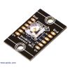
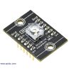
Since ShiftBrites are controlled by Allegro’s A6281 LED driver, careful reading of the A6281’s datasheet (315k pdf) is recommended. Each ShiftBrite input is buffered and output on the corresponding output pin. This allows you to chain together ShiftBrites without increasing the number of IO pins dedicated to controlling the modules. The picture below shows three ShiftBrites chained together.
 |
| Three ShiftBrites chained together. |
|---|
Pololu's 6", 12", and 24" cables for ShiftBrites make it easy to connect multiple modules, as shown below.
|
|


You can make your own shorter cables with Pololu's 3" wires with pre-crimped terminals and Pololu's 0.1" 6×1 crimp connector housings.
 |
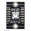
| Pinout diagram for the ShiftBrite module. |
|---|
Each ShiftBrite has a 32-bit shift register. When a rising edge is detected at the clock in pin (CI), the data in pin (DI) value is shifted onto the first bit of the shift register, and the last bit sets the value of the data out pin (DO). After you have loaded a 32-bit packet into the shift register of each ShiftBrite in the chain, bringing the latch in pin (LI) from low to high causes the data to take effect (changing the color or updating a configuration setting). LI must be brought low again before clocking in additional data.
The data packet format is shown in the picture below. For more details about the data packet format, as well as timing and other electrical parameters, see the A6281 datasheet (315k pdf). You can find further documentation and Arduino sample code at macetech’s ShiftBrite documentation page.
 |
| ShiftBrite packet diagram. The second row shows a color packet, while the third row shows a command packet. |
|---|
To send data to the ShiftBrite, you need to use at least three digital I/O pins (four if you want to use the EI pin). Pololu's Orangutan robot controllers work well for this. Here is some sample code for setting the colors of a chain of ShiftBrites using bit banging on the AVR. The chain can be arbitrarily long, but the changing color pattern will repeat on every sixth module.
| 1 2 3 4 5 6 7 8 9 10 11 12 13 14 15 16 17 18 19 20 21 22 23 24 25 26 27 28 29 30 31 32 33 34 35 36 37 38 39 40 41 42 43 44 45 46 47 48 49 50 51 52 53 54 55 56 57 58 59 60 61 62 63 64 65 66 67 68 69 70 71 72 73 74 75 76 77 78 79 80 81 82 83 84 85 86 87 88 89 90 91 92 93 94 95 96 97 98 99 100 101 102 103 104 105 106 107 108 109 110 111 112 113 114 115 116 117 118 119 120 121 122 123 124 125 126 127 128 129 130 131 132 133 134 135 136 137 138 139 140 141 142 143 | // ShiftBrite communication for the AVR using bit banging.//// Pin Assignments (any four free digital I/O pins will do)//// Data PC2// Latch PC3// Enable PC4// Clock PC5//// Feel free to modify and use this code for your AVR.#include <avr/io.h>typedef union ShiftBritePacket{ unsigned long value; struct { unsigned greenDotCorrect:7; unsigned clockMode:2; unsigned :1; unsigned redDotCorrect:7; unsigned :3; unsigned blueDotCorrect:7; }; struct { unsigned green:10; unsigned red:10; unsigned blue:10; unsigned command:1; };} ShiftBritePacket;// colorPacket returns a ShiftBritePacket for setting color brightnesses//// red, green, and blue are brightness values from 0 to 1023. 0 is off, and // 1023 is brightest.ShiftBritePacket colorPacket(unsigned int red, unsigned int green, unsigned int blue){ //Make a packet and initialize all of the bits to zero. ShiftBritePacket shiftbrite_packet = {value:0}; shiftbrite_packet.red = red; shiftbrite_packet.green = green; shiftbrite_packet.blue = blue; return shiftbrite_packet;}// commandPacket returns a ShiftBritePacket for sending commands to the A6281.//// redDotCorrect, greenDotCorrect, and blueDotCorrect lets you control what // percentage of current is flowing to each color diode. // Refer to page 8 of the datasheet for more information.// clockMode lets you set the PWM frequency for the diodes. // Refer to page 7 of the datasheet for more information.ShiftBritePacket commandPacket(unsigned int redDotCorrect, unsigned int greenDotCorrect, unsigned int blueDotCorrect, unsigned char clockMode){ //Make a packet and initialize all of the bits to zero. ShiftBritePacket shiftbrite_packet = {value:0}; shiftbrite_packet.redDotCorrect = redDotCorrect; shiftbrite_packet.greenDotCorrect = greenDotCorrect; shiftbrite_packet.blueDotCorrect = blueDotCorrect; shiftbrite_packet.clockMode = clockMode; shiftbrite_packet.command = 1; return shiftbrite_packet;}void sendPacket(ShiftBritePacket shiftbrite_packet){ for(int i = 1; i < 32 + 1; i++) { //Set the appropriate Data In value according to the packet. if ((shiftbrite_packet.value >> (32 - i)) & 1) PORTC |= (1 << PORTC2); else PORTC &= ~(1 << PORTC2); //Toggle the clock bit twice. PORTC ^= (1 << PORTC5); PORTC ^= (1 << PORTC5); }}void latch(){ // Set Latch high PORTC |= (1 << PORTC3); // Set Latch low PORTC &= ~(1 << PORTC3);}void sendColorWheelPacket(unsigned int location_on_wheel){ if (location_on_wheel < 400) sendPacket(colorPacket(400,(location_on_wheel % 400),0)); else if (location_on_wheel < 800) sendPacket(colorPacket(400-(location_on_wheel % 400),400,0)); else if (location_on_wheel < 1200) sendPacket(colorPacket(0,400,(location_on_wheel % 400))); else if (location_on_wheel < 1600) sendPacket(colorPacket(0,400-(location_on_wheel % 400),400)); else if (location_on_wheel < 2000) sendPacket(colorPacket((location_on_wheel % 400),0,400)); else if (location_on_wheel < 2400) sendPacket(colorPacket(400,0,400-(location_on_wheel % 400)));}int main() { // Set all to outputs. DDRC |= (1 << PORTC2); // Data In DDRC |= (1 << PORTC3); // Latch DDRC |= (1 << PORTC4); // Enable DDRC |= (1 << PORTC5); // Clock // Set the Enable output low to enable the ShiftBrites. PORTC &= ~(1 << PORTC4); //Have the ShiftBrites change from red to yellow to green to cyan to blue //to purple and back to red. while(1) { for (int i = 0; i < 2400; i++) { sendColorWheelPacket(i); sendColorWheelPacket((i+400) % 2400); sendColorWheelPacket((i+800) % 2400); sendColorWheelPacket((i+1200) % 2400); sendColorWheelPacket((i+1600) % 2400); sendColorWheelPacket((i+2000) % 2400); latch(); } } //Loop forever while(1);} |
Exact shipping can be calculated on the view cart page (no login required).
Products that weigh more than 0.5 KG may cost more than what's shown (for example, test equipment, machines, >500mL liquids, etc).
We deliver Australia-wide with these options (depends on the final destination - you can get a quote on the view cart page):
- $3+ for Stamped Mail (typically 10+ business days, not tracked, only available on selected small items)
- $7+ for Standard Post (typically 6+ business days, tracked)
- $11+ for Express Post (typically 2+ business days, tracked)
- Pickup - Free! Only available to customers who live in the Newcastle region (must order online and only pickup after we email to notify you the order is ready). Orders placed after 2PM may not be ready until the following business day.
Non-metro addresses in WA, NT, SA & TAS can take 2+ days in addition to the above information.
Some batteries (such as LiPo) can't be shipped by Air. During checkout, Express Post and International Methods will not be an option if you have that type of battery in your shopping cart.
International Orders - the following rates are for New Zealand and will vary for other countries:
- $12+ for Pack and Track (3+ days, tracked)
- $16+ for Express International (2-5 days, tracked)
If you order lots of gear, the postage amount will increase based on the weight of your order.
Our physical address (here's a PDF which includes other key business details):
40 Aruma Place
Cardiff
NSW, 2285
Australia
Take a look at our customer service page if you have other questions such as "do we do purchase orders" (yes!) or "are prices GST inclusive" (yes they are!). We're here to help - get in touch with us to talk shop.
Have a product question? We're here to help!
Guides

The Maker Revolution
Projects

The Rats Nest VCC Desktop Power Supply

Remote-Controlled Mars Rover

FlipperMate: Hands-Free Pinball

Makers love reviews as much as you do, please follow this link to review the products you have purchased.
Product Comments