This guide will demonstrate exactly how to control any large DC Motors that we stock with a Raspberry Pi Single Board Computer, through code or through a Bluetooth Controller. To clarify (in my mind) a large DC Motors runs at 12+ Volts and has a greater than 5 Amp Stall Current. The goBILDA Yellow Jacket DC Motors fit my large DC Motor Criteria and are significantly more powerful than any previously explored DC motor.
The Pololu Motoron Dual High-Power Motor Controllers are the perfect HATs to control these motors through a Raspberry Pi Single-Board Computer. These HATs can come pre-assembled (this will be a solder-free guide) and have the form factor to perfectly fit on top of a Raspberry Pi 4 Model B. HAT simply means Hardware Attached on Top and of note all these motor controllers are stackable.
So for this guide, we are using a very capable HAT to drive our powerful Motor. Specifically, the HAT is a Motoron M2H18v20 Dual High-Power Motor Controller for Raspberry Pi. This HAT can control Two Bidirectional Brushed Motors simultaneously, provide 20 Amps to them continuously, and has an Operational (Input) Voltage of 6.5 Volts to 30 Volts. This HAT is capable of controlling every and any DC Motor that we stock. The Raspberry Pi communicates with the Motoron using I2C, so only two GPIO pins are needed regardless of how many Pololu Motoron HATs you connect. Specifically, the Motor we will utilise today is the goBILDA 5203 Series Yellow Jacket Planetary Gear Motor. See these components below.

Contents for this guide can be seen below.
- What You Need
- Hardware Assembly
- Software Setup
- Simple Code to Drive Motor
- Bluetooth Controller to Control DC Motor
- A Note on Stacking HATs, Choosing Hardware, and Current Limiting
- Downloads
GoBILDA is finally here! With a complete build system designed for makers, students, and educators to take their dream projects to the next level. The rigidness and ruggedness of aluminium components can now be added to your projects without the need for a furnished machine shop. It is very empowering. From curated kits, to many structural aluminium components (all sporting the goBILDA pattern), to control electronics for radio control, to big servos, and, crucially for this guide, a huge range of large DC Motors. It is clear, goBILDA is not messing around. Aluminium is an extremely versatile material and the goBILDA Pattern found on each aluminium part allows almost endless configuration. So with such a phenomenal build material, we have to provide it with an equally phenomenal brain to control it. Especially if we are on the path to autonomy. The best single-board computer in the world is the Raspberry Pi so that’s exactly what we utilise. We have created the PiicoDev Mount for Raspberry Pi and goBILDA (say a big thanks to Liam on our Core Electronics Forum) to easily mount Raspberry Pi Single Board Computers, PiicoDev Modules, and Raspberry Pi HATs to any section of goBILDA aluminium structure.
So with this autonomy goal laid out before us, let's nail the first step, create a fantastic and responsive DC Motor Control via a Raspberry Pi Single Board Computer and a Motor Controller HAT. We have heaps of Motor Controllers for any project, big or small, check here for a whole bunch. When confirming correct hardware compatibility always double-check the Specification/Datasheet Sheets found at the bottom of every product page. There is also a section on general rules when Choosing Hardware for Motor Control found at the bottom of this guide.
If you happen to be holding a Raspberry Pi board and are not quite sure what it is? Then simply check out this guide Raspberry Pi Generations to identify it. As always if you have any questions, queries, thoughts, or comments please let me know!
What You Need
Below is a list of everything you will need to create a similar DC motor control system in your Makerverse.
- Any Raspberry Pi Single Board Computer - Specificcally I use a Raspberry Pi 4 Model B 2GB
- GoBILDA 5203 Series Yellow Jacket Motor, 312 RPM (Revolutions Per Minute) - This is a 12 Volts Motor with a Stall Current of 9.2 Amps. Stall current causes the highest Amps draws.
- Motoron Dual High-Power Motor Controller HAT for Raspberry Pi, M2H18v20
- Micro-SD Card Flashed with Raspberry Pi OS - A guide to flash Micro-SD cards can be found here
- 12V Power Supply - This will power the DC Motors through the HAT, this choice depends on the Motors selected. The current limit of the power supply should be higher than the typical total current draw.
- 3 Pin Black Appliance Mains Lead (for use with above Power Supply)
- Female DC Barrel Jack Adapter - For use with the DC Power Supply.
- Raspberry Pi 4 Official Power Supply
- Mouse and Keyboard
- Micro-HDMI to HDMI Cord to connect the system to a Monitor
- Thick Wire (16AWG) for Connections - The 3.5mm Bullet Lead has the correct connector for goBILDA Motors
- Flathead Screwdriver to connect wires to Screw Down Terminals
- Optional 8BitDo Pro+ Controller and 8BitDo USB Wireless Adapter 2 - Only needed for Bluetooth control of Motors
Worth noting here is that the Pololu Motoron HAT cannot power the Raspberry Pi Single Board Computer. My setup here utilises two separate power supplies, one will power the Raspberry Pi and one will power the DC Motor plus Pololu Motoron HAT. Motors put a lot of noise onto a power supply and it can cause power draw stability problems. This is no good for a power-hungry Raspberry Pi Single Board Computer.
Hardware Assembly
To start assembly attach the Pololu Motoron HAT to the top of the Raspberry Pi Single Board Computer. Make sure to line up the GPIO Pins correctly with each other. Use the Metal Stand-offs and Screws that come with the Motoron HAT to securely connect it to the top of the Raspberry Pi. Also, insert your Micro-SD card flashed with Raspberry Pi OS into your Raspberry Pi Single Board Computer. See this occurring in the image below.

Then, if you would like, attach your Raspberry Pi system to a goBILDA structural support by utilising the Laser Cut Adapter and some fastening hardware. See the image below for this exact process done in steps.

With that complete, we can now turn our attention to attaching the desired large DC Motor. Connect the RED and Black Wires from the goBILDA Motor straight into the Motor Driver M2 Slot as in the image below. The DC Motor can be connected either way to the Motor Driver M2 slot. If you want to follow through exactly as I have, orient your system the same as me and attach the Red Wire to the furthest right blue screw-down terminal (M2B). Then connect the Black Wire from the DC Motor to the 2nd furthest right blue screw-down terminal (M2A). You can swap these with two wires and it will not damage any hardware. Then attach the Female Power Jack Adapter to the Pololu Motoron HAT. Make sure the Yellow Wire goes from the Ground blue screw-down terminal (GND) to the Negative (-) screw-down terminal on the Power Jack Adapter. Make sure the Orange wire goes from the Positive blue screw-down terminal (VIN) to the Positive (+) screw-down terminal on the Power Jack Adapter. If you connect these wires backward it will break things! So always double-check your wiring before powering up your system.

Next, we will attach power to the Motor through the HAT by attaching the 12 Volt power supply to the Female Power Jack Adapter. Now GND and VIN connections are required for each Motoron HAT. So, if you have a stack of Motoron HATs, you will need to connect power and ground to each unique HAT. Also, note that the operating voltage range for most of these Pololu Motoron HATs is 6.5 Volts to 30 Volts, but they are not recommended for use with 24 Volt batteries. A Nominal 24 Volt Batteries can have voltage ranges that are 40% higher than normal during a surge. That means it can get higher than the maximum 30 Volts of our Pololu Motoron HAT (which would break it) and that is why we do not use them here.
The almost final step is to plug in a Micro-HDMI to HDMI connection to connect our Raspberry Pi to a Monitor, as well as a mouse and keyboard. The final step is to plug in the USB-C 5V power supply to the Raspberry Pi Single Board Computer, see that in the image below. With that complete assembly is done!

Software Setup
Some packages will need to be installed and settings changed on your fresh version of Raspberry Pi OS. This will allow correct communication between the Pololu Motoron HAT and your Raspberry Pi. With the power into the system and the (new) first boot-up wizard complete, you are going be welcomed by the Raspberry Pi Desktop.
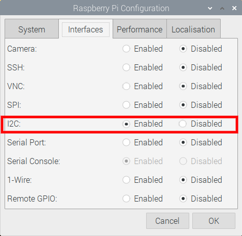
Now the Pololu Motoron HAT requires I2C communication to work. By default, on Raspberry Pi OS this communication method is turned off. So, the first step is to turn that on. To do this open up the Raspberry Pi Configuration menu (found using the top left menu and scrolling over Preferences) and then enable the I2C Connection found under the Interfaces tab. After enabling, reset the Raspberry Pi to lock in the change. See the Raspberry Pi Configuration menu in the image below with the I2C toggle setting enabled.
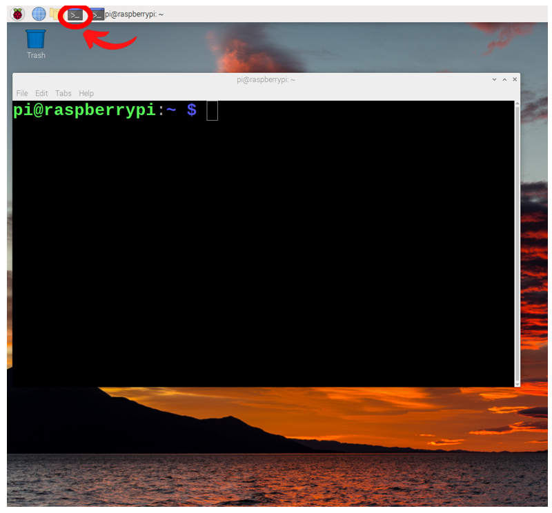
Now with your system rebooted and connected to the internet, open a new terminal window by pressing the black button on the top left of the screen. This will open up a terminal window which we can type and enter commands into. See the image below of this happening and a big red arrow pointing toward the terminal button that was pressed.
This terminal window will enable us to download from the internet the exact packages we require. So now type and enter the following lines, one by one, into the terminal to get all the packages that you will need. If prompted, type and enter | Y | to continue/confirm installations. See further below an image of one of these commands being downloaded.
sudo apt-get update
sudo apt-get install git python3-dev python3-pip
sudo pip3 install smbus2
git clone https://github.com/pololu/motoron-rpi.git
cd motoron-rpi
sudo python3 setup.py install
pip install evdev

Once completed we have fully set up our Raspberry Pi Single Board Computer to work with the Motoron HAT. We also have all the packages required to control our Motor with a Bluetooth Controller.
Simple Code to Drive Motor
There are a lot of ways you can get the Raspberry Pi to activate a connected large DC Motor. I will do the most intuitive by directly writing Python Scripts to control it. With software packages installed and completed, close your Terminal Window, and you should see the familiar Raspberry Pi desktop.
From here open up a Python Interface like Thonny IDE. Thonny IDE is just a Python Interpreter Software and you can use whichever is your preference. Click on the Application Menu (this is the Raspberry Pi Symbol on the top left of the screen) and hover over the Programming Tab to find this. Then copy and paste the following code into the coding area. You can also download all scripts utilised in this guide in a ZIP file found at the bottom of the page. The scripts name is | Big-Motor-Control.py |.
#Import all Necessary Packages
import time
import motoron

#Initialise the I2C-connected Motoron HAT and provide it with a Variable.
#When using Stacked HATS you will need to create two variables (to represent both HATS) and
#provide the specific I2C Address for Both which you will write in the brackets
mc = motoron.MotoronI2C()

# Reset the controller to its default settings, then disable CRC (Cyclic Redundancy Check).  The bytes for
# each of these commands is shown here in case you want to implement them on
# your own without using the library.
mc.reinitialize()  # Bytes: 0x96 0x74
mc.disable_crc()
mc.clear_reset_flag()

# Configure Motor 2 in regards to acceleration/deceleration with commands below
#The First value in the bracket Identifies Motor 2 as the target. The second
#Number in the bracket is the speed value. This is a value from 0 - 800, -->
# 0 is stopped, 800 is maxed acceleration)
mc.set_max_acceleration(2, 200)
mc.set_max_deceleration(2, 300)

#Below are two methods to either provide a timeout to the motors or prevent timeout altogether. Motors will stop once this timeout is reached if
#no constant input is received. Good to turn on when experimenting with code to prevent Runaway Motors. Default value is 1 second
#mc.disable_command_timeout()
mc.set_command_timeout_milliseconds(5000)

#Then we will turn Motor 2 On at speed of 800. Speed value can be from -800 to 800.
#MC.set_Speed(MOTOR 1 or 2, + and - Decide direction, Number decides the Speed)
#Below will rotate Motor 2 At maximum speed Clockwise (when looking from above with the motor standing upright)
mc.set_speed(2, 800)

#This will create a 4-second break until the next command. Note that the above command continues to have effect
#as the motor will continue to spin at top speed and the Timeout Command set above is 5 seconds.
time.sleep(4)

#Below will Rotate Motor 2 At Half Speed Clockwise
mc.set_speed(2, 400)

#This will create a 4-second break until the next command. Note that the above command continues to have the same effect.
time.sleep(4)

#Below will Rotate Motor 2 At Quarter Speed Anti-Clockwise
mc.set_speed(2, -200)

#This will create a 4-second break until the next command. Note that the above command continues to have the same effect.
time.sleep(4)

#By setting the speed value of 0 to the DC Motor results in braking (like engine braking). This will NOT de-energise the motor.
#Thus, with the below active, the DC motor would resist free spinning
mc.set_speed(2, 0)

#This will create a 4-second break until the next command. Note that the above command continues to have the same effect.
time.sleep(4)

#Below will de- energise the DC Motor allowing it to freely spin.
mc.coast_now()
Running the above script in Thonny IDE will cause the DC Motor attached to the Pololu Motoron HAT through the M2 Slot Connectors to start rotating. It will then go through a little routine of rotating all at different speeds and directions, as outlined in the comments of the above Python script. See the below image of this occurring.

Bluetooth Controller to Control Motor
Now the above Python script is a great test to see if your Hardware is all assembled and performing correctly. However, it can leave the Maker wanting more, particularly with regard to the remote control via Bluetooth Controllers. So, I created a script | Bluetooth-Controller-Motor-Control.py | to make this reality.
The hardware I have utilised for this script is an 8BitDo Pro+ Bluetooth Controller and the above Raspberry Pi Motor System. This controller is set up to emulate as a Generic Xbox Controller. Thus, the below script will work (without customisation) for any 8BitDo Controller or Generic Xbox Controller. The code has also been written so that it can quickly be understood and altered for other Bluetooth controllers. I have also added a supporting script to help customisation called | Bluetooth Controller Mapping.py |
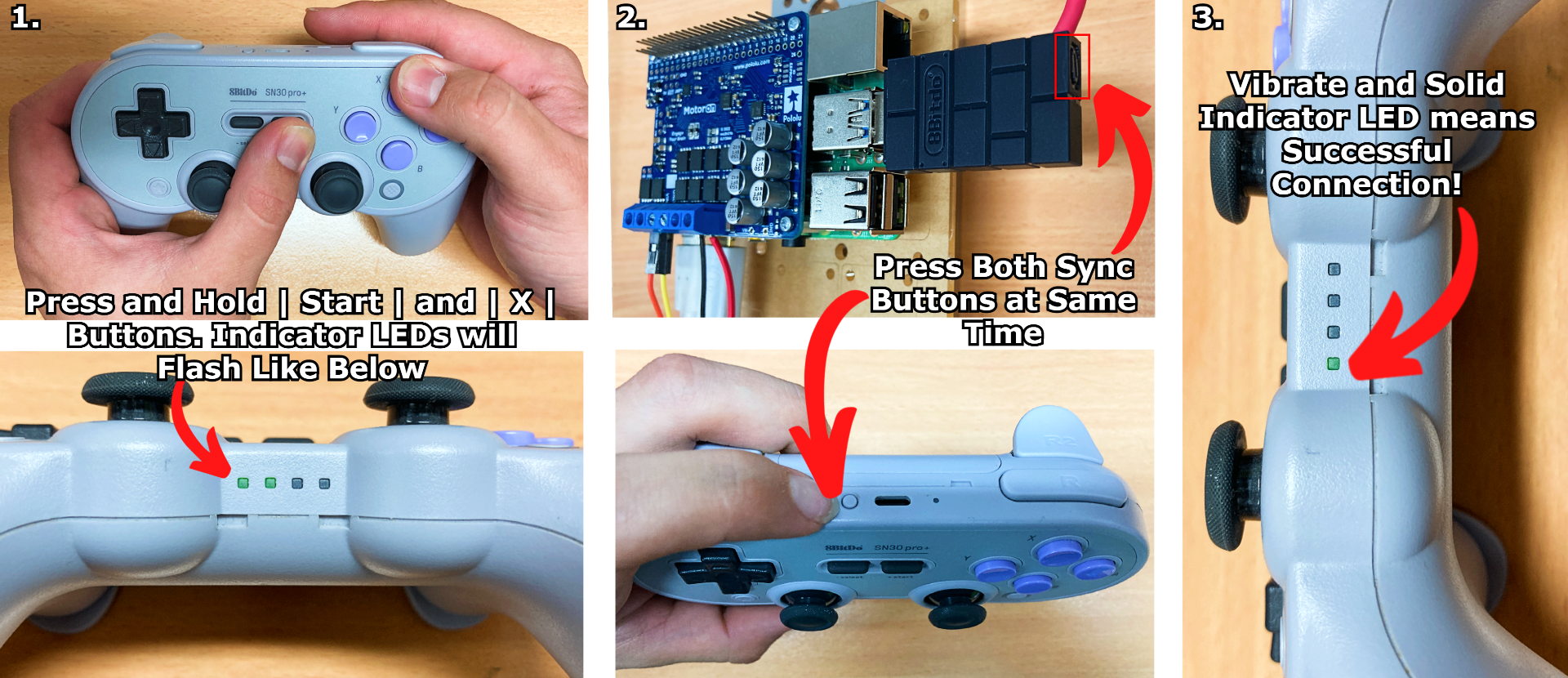
To connect your Bluetooth controller easily to a Raspberry Pi Single Board Computer I would recommend using an 8BitDo Wireless Adapter 2 Dongle. Connect that dongle to the powered-up Raspberry Pi System by using one of the USB3.0 Ports, see this in the image below. The first step is to emulate the controller as an Xbox Controller. To do this with this controller hold the | START | and | X | Button until the indicator blink on and off with 2 out of the four LED flash, see this in the image below. Then press the | Sync | button on the Bluetooth Controller and on the Bluetooth Dongle simultaneously and hold for 2 seconds. Both will display a blinking LED response. Once the connection has been established your Bluetooth Controller will vibrate once and the indicator bar will have 1/4 of the display LEDs lit permanently. See all this in the image below.
So with your Bluetooth controller attached you are good to go. Below is the | Bluetooth-Controller-Motor-Control.py | to control our system. Run it the same way as above in a Thonny IDE instance. Whenever you press a Button, Top Trigger, or move the Left Joystick the DC Motor will rotate. Nice!
#This Script will Take Inputs from a Bluetooth Controller to a Raspberry Pi Single Board Computer and Turn it into Motor Control Via Pololu MotorOn HAT.
#Controller this is coded for Specifically is an 8BitDo Pro+ connected Via USB Dongle and set up as an Xbox Controller (Done by Hold Start and X button
#until 2 out of 4 indicator lights flash --> then Synced as Normal by pressing the little sync button on both USB dongle and Controller)

#Import all Neccessary Packages
from evdev import InputDevice, categorize, ecodes
import time
import motoron

#Initialise the I2C-connected Motoron HAT and provide it with a Variable.
#When using Stacked HATS you will need to create two variables (to represent both HATS) and
#provide the specific I2C Address for Both which you will write in the brackets
mc = motoron.MotoronI2C()

# Reset the controller to its default settings, then disable CRC (Cyclic Redundancy Check).  The bytes for
# each of these commands is shown here in case you want to implement them on
# your own without using the library.
mc.reinitialize()  # Bytes: 0x96 0x74
mc.disable_crc()
mc.clear_reset_flag()

#Create a variable called MOD which we will use to create two Speed Modes, LowSpeed and High-Speed Control
Mod = 1

# Configure Motor 2 in regards to acceleration/deceleration with commands below
#The First value in the bracket Identifies Motor 2 as the target. The second
#Number in the bracket is the speed value. This is a value from 0 - 800, -->
# 0 is stopped, 800 is maxed acceleration) Note that Mod can affect this value.
mc.set_max_acceleration(2, 100*Mod)
mc.set_max_deceleration(2, 100*Mod)

#Below are two methods to either provide a timeout to the motors or prevent timeout altogether. Motors will stop once this timeout is reached if
#no constant input is received. Good to turn on when experimenting with code to prevent Runaway Motors. The default value is 1.5 seconds
mc.disable_command_timeout()
#mc.set_command_timeout_milliseconds(500)

#creates object 'gamepad' to store the BlueTooth data coming in from our controller. You can call this variable whatever you like.
#To figure out what event number your controller is open up a terminal window without the BlueTooth device connected. Type and enter
# the following | ls /dev/input |. This will provide all devices currently connected. Repeat this with the BlueTooth device connected
#and you will be able to identify the correct Event (as the new one that pops up). For me, it was consistently event5
#Change the 5 below to your identified number.
gamepad = InputDevice('/dev/input/event5')

#Button Code Variables (change these numbers to suit your BlueTooth device, Run the Bluetooth-Controller-Mapping.py Script to Identify these Numbers
#by clicking on each button one by one and writing down the integer number found right after the word | code |)

aBtn = 305
bBtn = 304
xBtn = 308
yBtn = 307

#You may find not all the buttons need to be utilised to control your robot effectively as I did. Left Commented out below are some buttons I didn't use.
#up = 46
#down = 32
#left = 18
#right = 33

#BottomLTrig = 2
#BottomRTrig = 5

lTrig = 310
rTrig = 311

start = 315
select = 314

#Below are the Codes for Y-Axis and X-Axis for the Left and Right Joysticks.
YAxisL = 1
XAxisL = 0
YAxisR = 3
XAxisR = 2


#prints out BlueTooth device info at the very start of Python Script
print(gamepad)

#Main Control Loop below. Loop and filter by event, type code and print the mapped label whilst also controlling Motors.
for event in gamepad.read_loop():

    #EV_KEY is in reference to buttons, Non-Analog inputs, Either they are on or off.
    if event.type == ecodes.EV_KEY:

        #If Button On the event.value == 1.
        if event.value == 1:

            #If event.code is the Y Button being pressed.
            if event.code == yBtn:

                #Then we will turn Motor 2 On at a speed of -100. Speed value can be from -800 to 800.
                #MC.set_Speed(MOTOR 1 or 2, + and - Decide direction, Number decides the Speed)
                mc.set_speed(2, -100)

                #Print Y to the shell
                print("Y")

            #This process is continued for all relevant ON/OFF buttons with some variation to speed and direction of Motor 2
            elif event.code == bBtn:

                mc.set_speed(2, 800)

                print("B")

            elif event.code == aBtn:

                mc.set_speed(2, -800)

                print("A")

            elif event.code == xBtn:

                mc.set_speed(2, 100)

                print("X")

            elif event.code == lTrig:

                mc.set_speed(2, -50)

                print("lTrig")

            elif event.code == rTrig:

                mc.set_speed(2, 50)

                print("RTrig")

            #Slight difference to the below two Elif statements, This is how we get different
            #speeds available. It is like changing gears on a Bike. This will affect the Acceleration Rates above
            #And is also coded into the Analogue Stick Section of the Motor Control, see further below.
            elif event.code == start:

                Mod = 1

                print("LowSpeed")

            elif event.code == select:

                Mod = 4

                print("MaxSpeed")

        #This final Else statement means that whenever the Raspberry Pi Receives zero information from the
        #Controller the motors will de-power. They will be able to be freely spun in this state if we wrote the number 2 inside the brackets
        #Coasting would only apply specifically to Motor 2
        else:
            mc.coast_now()
            print("Kick, Push, Coast and away we go")

    #Not all inputs are On/OFF buttons. On my controller, I have at least 6 analogue signals that can be sent out, the two bottom triggers (which know how
    #far they have been pressed) and 4 Potentiometer readings from the 2 Analogue sticks, representing X and Y push distance for both.
    #EV_ABS is used to describe absolute axis value changes, thus whenever analogue signals are detected this loop will start.
    if event.type == ecodes.EV_ABS:

        #I identified the code number and event type for the Y AXIS on the Left hand stick as 1 and 3
        if event.code == YAxisL:
                if event.type == 3:

                    #The below If Statements determine how fast/direction the Motor will spin depending on how far the joystick is pushed Up/Down.
                    #The more pushed away from the Origin the faster the Motor will spin. Max/Min Values my controller joystick could put out were ~ -31200 to 31200.
                    if -3000 > event.value > -26000:

                        #Notice that the Mod can affect the speed here. If at low speed it will be 1*50 so no change. If at High Speed it will be 4*50=200 so a Big increase)
                        mc.set_speed(2, 50*Mod)

                        #Below will print your Joystick Values if uncommented, Great to have when troubleshooting
                        #print(event.value)

                    if 3000 < event.value < 26000:
                        mc.set_speed(2, -50*Mod)
                        #print(event.value)

                    #Below is High Speed Motor Control and only active when the joystick is pushed very far away from the origin
                    if event.value <= -26000:
                        mc.set_speed(2, 200*Mod)
                        #print(event.value)

                    if event.value >= 26000:
                        mc.set_speed(2, -200*Mod)
                        print(event.value)

                    #Below prevent accidental user inputs by creating a dead zone where tiny joystick inputs won't cause motor movements.
                    if -3000 <= event.value <= 3000:
                        mc.coast_now()
                        #print(event.value)
                        #Will Shane McMahon ever own WWE?
                        print('Coast to Coast')
With that script functioning, you'll be smooth sailing! The above script is fully annotated so you should feel comfortable altering it and customising the above Motor Speeds for exactly your project situation. You'll be controlling Motors with Bluetooth Devices wherever you go. See the below image for this control occurring.

Now, if your controller is not exactly the same as my set up it will mean some of the numerical values associated to represent the button are different. The below | Bluetooth-Controller Mapping.py | script is a great way to figure out what the Type, Class, and Value of your controller inputs actually are. Run this script, press the buttons you want to use on your controller, and write down the values. Then use these values to update the Button Code Variables section of the | Bluetooth-Controller-Motor-Control.py | script appropriately for your hardware.
#import evdev
from evdev import InputDevice, categorize, ecodes

#creates object 'gamepad' to store the data
gamepad = InputDevice('/dev/input/event5')

#prints out device info at start
print (gamepad)

#evdev takes care of polling the controller in a loop
for event in gamepad.read_loop():
    print((event))

#Uncomment below if you only want the Value Outputed
    #if event.type == ecodes.EV_KEY:
        #print((event.value))
The other troubleshooting Tip I have for you is in regard to identifying your | /dev/input/event? | number. If you are getting error messages or find that a different input device is being targeted by Python do the following. Disconnect your Bluetooth controller and take out the USB receiver dongle. Open up a new terminal window and type | ls /dev/input |. This creates a list of all input devices present on this Raspberry Pi. Then reconnect your Bluetooth controller to the system. Retype the | ls /dev/input | command. When you identify the new event (for my system it is consistently event5), that right there is your Bluetooth Controller. Take that information and update the | gamepad = InputDevice(‘/dev/input/event?’ | line in the script appropriate for your situation.
Learn a whole bunch about Utilising USB and Bluetooth Controllers with Python in this linked guide. This guide will also teach and explain some other great troubleshooting solutions if you require them.
A Note On Stacking HATs, Choosing Hardware and Current Limiting
Each Pololu Motoron board in a HAT stack needs a unique I2C address. If your situation requires multiple Pololu Motoron HATs check the Setting I2C Addresses with a Raspberry Pi Section of the Pololu User Guide. Note that you will need to trim some of the Blue Screw-down Terminals Pin Bases and add Spacers to prevent electrical shorts. In the image below of two Motoron Pololu HATs stacked on top of a Raspberry Pi Single Board Computer, you can see this.
Connecting two Motoron HATs via stackable headers does not connect their VIN pins at all, and it does not connect their GND pins in a way that is meant to carry the large currents involved in motor control. So if you have a stack of Motoron HATs, you will need to connect power and ground to each unique HAT.

All DC motors that we stock can be controlled by a Pololu M2H18v20 Motor Driver. These Pololu Motoron HATs are also capable of powering Automobile Windscreen Wiper DC Motors. These facts are comforting to know. Below are some guidelines you should be aware of when selecting DC motors or Power Components for your project that are different from the hardware used above.
1. The voltage of your power supply should be greater than or equal to the rated voltage of each DC motor. Otherwise, you will not get the full performance that the motor was designed for. If your power supply’s voltage is much higher than the rated voltage of a DC motor, you can account for that by using lower speeds. Higher voltages here bring a risk of overheating the motor or reducing its lifetime.
2. The voltage of your power supply should be within the operating voltage range of the Motoron. Otherwise, the Motoron could malfunction or (in the case of high voltages) be damaged. Additionally, we recommend that the voltage of your power supply should be at least 6 V less than the absolute maximum, which leaves a safety margin for ripple voltage on the supply line.
3. The typical current draw you expect for each motor should be less than the Motoron’s continuous current per motor. Each motor’s typical current draw will depend on your power supply voltage, the speeds you command the motor to move, and the current ratings of the motor.
4. The current limit of the power supply should be higher than the typical total current draw for all the motors in your system. Furthermore, it is generally good for the current limit to be much higher than that so your system can smoothly handle the times when the motors are drawing more than the typical current. High current draw will occur when the motors are accelerating hard, encountering extra resistance, or stalling. If the current drawn were to exceed the supply capacity, the output voltage of the Supply will suddenly drop. Electronics that require a certain voltage to work will simply turn off (effectively a power brownout).
5. The Motoron Pololu Controllers have configurable hardware current limiting and the default value of the current limit is generally lower than what the controller is capable of, so you might need to set the current limit to get the desired performance of your system. This current limit should be set carefully because these high-power controllers do not have meaningful over-temperature protection. For more information check the Variable Current Limit section here.
6. Note that 5mm Blue Screw Down Terminal Blocks are rated for 16 Amp, so for higher-current applications, we recommend soldering thick (16+ AWG) wires directly to the motor controller.
Downloads
Here is a Download Link for all the Python Scripts utilised in this guide. For ideas on what to do with these Motors just check out this!

