Force-sensitive resistors (FSR) are remarkable electrical components and are proper unsung heroes in the Makers World. Name me a better variable touch input device which has basically no moving parts, all whilst being available in such a tiny form factor. Only FSR components meet that criteria. They are perfect for detecting touch, and qualitatively measuring rate and relative changes in force/pressure. This ability comes from the fact that FSR components significantly decrease in resistance when a force/pressure is applied to their sensing pads.
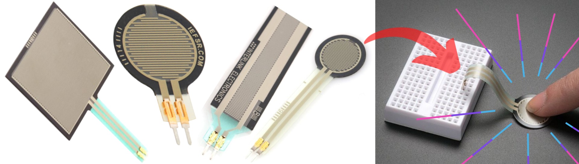
With an FSR component built into a case and set up to a device that can measure voltages or resistance and you've got yourself an analogue, rugged, input device. So let's explore FSR further with a Raspberry Pi Single Board Computer. See a number of different FSR variants in the image below as well as one connected to a breadboard.
This will explore two methods of control when utilising Force Sensitive Resistors, Simple and Analogue. The endpoint of the simple setup will know exactly when the resistor is under force/pressure. The endpoint of the analogue setup will let us detect different magnitudes of force/pressure. See below for the contents of this guide.
- How They Work
- What You Need (Simple and Analogue Set Up)
- Simple On/Off Set Up
- Software Set Up
- Reading Analogue Data from Force Sensitive Resistor
- Where to Now (3D Printed Case & Controlling a LED Glowbit Stick Based on Pressure)
- Downloads and Addendum
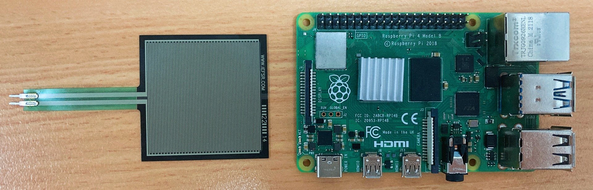
So come add a rugged touch interface to your next project, create a robot with sophisticated tactile senses or simply repair your footpad on your Onewheel/Floatwheel Board. In the image below is a force-sensitive resistor with a square sensing area (40mm X 40mm) situated next to a Raspberry Pi 4 Model B. Same for all FSR components, this Square FSR will vary its resistance depending on how much pressure is being applied to the sensing area. The harder the force, the lower the resistance. When no pressure is being applied to the Square FSR its resistance will be larger than 1MΩ. It can then range from 100 kΩ (from a light touch) to a few hundred Ohms (from a heavy squeeze). This square FSR can sense weight anywhere in the range of 100g-10kg. The resistance is very stable when the pressure is fixed, and the readings are very repeatable.
Note that these FSR components are not a replacement for load cells or strain gauges. FSR Components will never be suitable for precision force measurements due to them being highly non-linear and less accurate. While FSR can often be used for high-resolution dynamic measurement, when low weight and footprint are desirable (FSR components are often utilised in Midi Pad designs), only qualitative results are generally attainable. However, if you want to make a really accurate scale I have a great solution for you here, the Makerverse Load Cell Kit!
Now as incredible as Raspberry Pi Single Board Computers are by default they have no way of reading pure Analogue signals. This is fine for our Simple Set Up, as it will indicate whether there is pressure on the Force Resistor or not. However, to see the gradient as the pressure increases we will need an ADC (Analogue to Digital Converter) to translate between these two systems. An ADC board, like the ADS1015 from Adafruit, converts analogue signals into a digital representation so that they can be read and processed by the Raspberry Pi. Most sensors like temperature, sound, microphones or force produce/measure/affect analogue voltages and the Force Sensitive Resistor is no exception.
As always if you have any questions, queries, or things you'd like me to do with this system, please let us know your thoughts!
How They Work
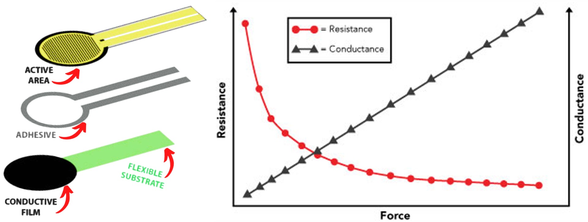
These FSR components have a huge amount of resistance at normal state yet when they are pressed they drop resistance significantly. The best way to understand how it is doing this is to separate it into base components. Every Force Sensitive Resistor is made up of layers. These are an Active Area Layer, usually a flexible PCB with well-considered traces, a Pressure Sensitive Conductive Film Layer, and an Adhesive Layer keeping it all together. You can see an exploded view of these layers, as well as a graph showing the expected response due to force, in the image below
These carefully considered traces on that flexible PCB layer are crucial to correct operation. Below is a force-sensitive resistor with a square sensing area and a microscope zoomed-in version of the top of the square. I have altered the colours of the traces so you can more clearly understand that the two sides of active area traces do not directly connect to each other. Only when pressure is applied will electricity be able to flow easily as it can route through the conductive film layer. This particular Square FSR has a greater than 1 Million Olm Resistance when unpressed. When the pad is pressed hard (allowing the electrons to flow through the conductive film thus 'jumping' it across the traces) the resistance decreases to ~20 kOlms. That is an order of magnitude difference.

All the Force Resistors that will be explored here are single-point force sensors. From these, we can only obtain quantitive readings. The data obtainable from these single-point resistors are as follows: Detecting or measuring a rate of change in force, detecting or measuring a relative change in force, and detecting contact/touch. Any of this data can then be used as thresholds to trigger an action/effect.
What You Need
Below is everything you need to set up your Raspberry Pi to utilise a Force Sensor Resistor.
- Any Raspberry Pi Single Board Computer
- A Force Sensor Resistor (Here I utilise the Square FSR Variant)
- One 10K Resistor
- DuPont Jumper Connectors (Female to Male and Female to Female)
- Micro SD Card flashed with Raspberry Pi OS
- Solderless Breadboard
- Micro-HDMI to HDMI Cord to connect the system to a Monitor
- Power Supply
- Mouse and Keyboard
- ADS1015 12-Bit ADC – 4 Channel with Programmable Gain Amplifier (Optional Part, needed only for Analogue Readings)
Simple Set Up
To start, setup your Raspberry Pi as a desktop computer. Insert a micro-SD card flashed with Raspberry Pi OS, and add a mouse, keyboard, and HDMI to a monitor. This guide will assume you can do this, if you need an extra hand or more knowledge, come check this linked guide right here. For the simple set up we will not need to download any extra packages or make changes to our Default Raspberry Pi Configuration.
Now before plugging in the USB-C Power supply let's make some connections from the GPIO to our Force Sensitive Resistors. You can see the completed hardware setup in the image below. I utilise a breadboard to do this, if you need any extra knowledge on how the breadboard functions check this linked guide here. Be gentle when sliding the FSR components into the breadboard as they are delicate on that connector side. Once all those connections are made power up the Raspberry Pi System by plugging in that USB-C power supply.

To clarify the above, the Red Jumper Wire connects to a 5V Pin of the Raspberry Pi. The Black Jumper Wire connects to a Ground Pin on the Raspberry Pi. The Blue Jumper Wire connects to GPIO 4 Pin on the Raspberry Pi, this will act as our Sniffing Wire. That Blue Sniffing Wire will tell our Raspberry Pi whether the FSR is being pressed. If you need here is a fantastic website when it comes to identifying GPIO Pins on Raspberry Pi Single Board Computers. On the breadboard be aware that all holes that are in a connected column are electrically connected together.
Now that you have plugged in power into your system you will be greeted by the Raspberry Pi Desktop. From here open up a Python interface like Thonny IDE. Thonny IDE is just a Python Interpreter software and you can use whichever is your preference. In this guide, we will code using the Python Programming Language. Click on the Application Menu (this is the Raspberry Pi Symbol on the top left of the screen) and hover over the Programming Tab to find (and click on) the Thonny IDE Icon. This will open Thonny IDE. Then copy, paste and save the below script into the coding area. You can also download all scripts utilised in this guide in a Zip file found at the bottom of the page.
#Start by importing all necessary libraries and packages
import RPi.GPIO as GPIO
import time

#Set the GPIO to BCM Mode
GPIO.setmode(GPIO.BCM)

#Set Pin 4 to be our Sniffer Pin, We want this to be an Input so we set it as such
GPIO.setup(4,GPIO.IN)

#This variable will be used to determine if pressure is being applied or not
prev_input = 0

#Create a Loop that goes on as long as the script is running
while True:

    #take a reading from the pressure pad (based on the voltage able to get to pin 4)
    input = GPIO.input(4)

    #if the last reading was low and this one high the pressure pad is being pressed!
    if ((not prev_input) and input):

    #Print that fact to the shell, RIP David Bowie
        print("Under Pressure")

    #update previous input so we can avoid spamming the Shell with messages,
    #this section of the script is also a perfect place to add threshold values to active other devices
    prev_input = input

    #Have a slight pause here, also to avoid spamming the shell with data
    time.sleep(0.10)
Save the above Python Script as whatever you would like (in the download zip file it is named | simple-FSR-setup.py |) and put your system to the test by pressing the big green | Run | button! Now, whenever you press the pad it will respond with | Under Pressure | getting printed to the shell. You can see the result of pressing the pad with this script running in the image below. This script can readily be changed providing you with a fantastic rugged button that can control almost anything! GPIO (General Purpose Input and Output) Pins are the windows to controlling darn near every electronic system in this big world. Now you can control them all with an FSR.

Software Set Up
For this next section of the guide we will need to install some extra packages and change some software settings within Raspberry Pi OS. This will allow our Raspberry Pi Single Board Computer correctly communicate with the Adafruit ADS1015 ADC. For a whole bunch of knowledge regarding Analogue Signals into Raspberry Pi check this linked guide here.
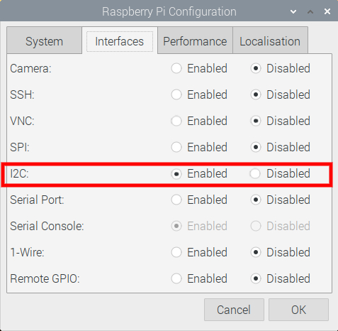
The Adafruit ADS1015 ADC requires I2C communication to work. By default on Raspberry Pi OS this communication method is turned off. So the first step is to turn that on. To do this open up the Raspberry Pi Configuration menu (found using the top left menu and scrolling over Preferences) and then enable the I2C Connection found under the Interfaces tab. After enabling, reset the Raspberry Pi to lock in the change. See this setting turned on in the settings window in the image below.
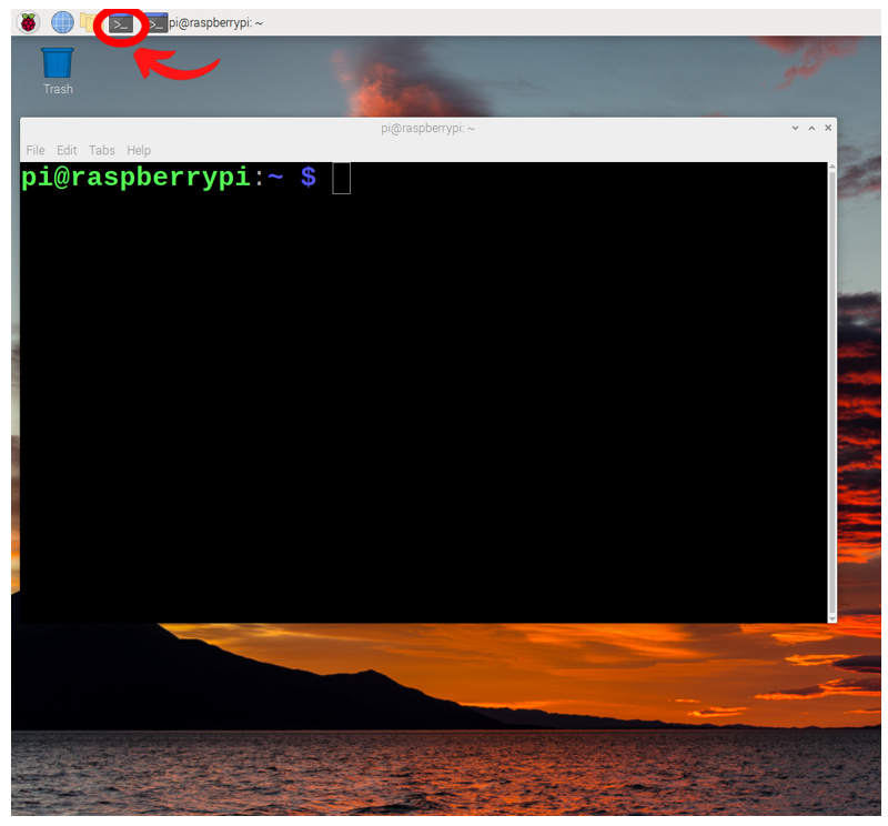
Now with your system rebooted and connected to the internet, open a new terminal window by pressing the black button on the top left of the screen. This will open up a terminal window. See the image below of this happening and a big red arrow pointing toward the terminal button that was pressed.
This terminal window will enable us to download from the internet the exact packages we require. So now type and enter the following lines into the terminal to get all the packages that you will need. If prompted, type and enter | Y | to continue/confirm installations.
sudo apt-get update
sudo pip3 install adafruit-ads1x15
sudo pip3 install adafruit-circuitpython-ads1x15
When completed we have fully set up the software of our Raspberry Pi Single Board Computer to work with the ADS1015 ADC Board and thus the analogue responses that FSR boards have.
Reading Analogue Data from Force Sensitive Resistor
With the above completed we can now turn our attention to incorporating the Adafruit ADS10115 ADC into our system. As we will be plugging new pieces into our Raspberry Pi's GPIO make sure to turn the power off to your system. A very quick way to send a Raspberry Pi to the grave prematurely is by not disconnecting power and then making a mistake when connecting up Jumper Wires to the GPIO Pins. So disconnect that USB-C Power supply! See the completed hardware assembly in the image below.
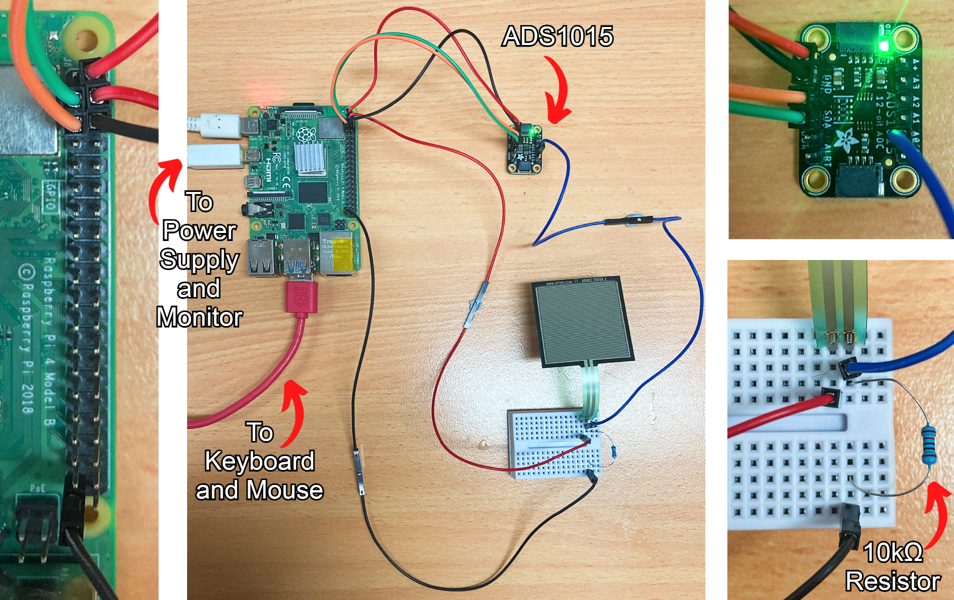
Now to be clear, no wires have been altered on the breadboard from the previous simple demonstration. The Blue 'Sniffer' Wire coming from the Breadboard has now been connected to the A0 Pin on the Adafruit ADS1015 ADC module. This Adafruit Module can run at 5V, so connect up the module to the second 5V Pin on the Raspberry Pi using a Red Jumper Wire. Then connect the Module to a Ground Pin on the Raspberry Pi using a Black Jumper Wire. This Module Requires I2C to operate correctly which is a two-wire protocol, requiring SDA (Serial Data) and SCL (Serial Clock) connections. Therefore connect the SDA Pin on the Raspberry Pi to the SDA Pin on the ADC Module. Connect the SCL Pin on the Raspberry Pi to the SCL Pin on the ADC Module. Double-check all your connections, then once sure that all is correct, put that USB-C Power supply back in.
Now that you have plugged in power into your system you will be welcomed by the Raspberry Pi Desktop. From here open up a Python interface like Thonny IDE just the same as before. Then copy, paste and save the below script into the coding area. You can also download all scripts utilised in this guide in a Zip file found at the bottom of the page.
#import all necessary functionality to the Script
import time
import Adafruit_ADS1x15

# Create an ADS1015 ADC (16-bit) instance. Note you can change the I2C address from its default (0x48) and/or bus number
adc = Adafruit_ADS1x15.ADS1015(address=0x48, busnum=1)
# Choose a gain of 1 for reading voltages from 0 to 4.09V.
GAIN = 1
#Create a Loop that repeats forever
while True:
    #Read the value coming from Analogue In Pin 0, set gain to the above value
    values = adc.read_adc(0, gain=GAIN)
    #Print the values to the shell, right click shell to enable the plotter
    print(values)
    #pause for just a tiny fraction of a second (so as not to be overwhelmed by data)
    time.sleep(0.1)
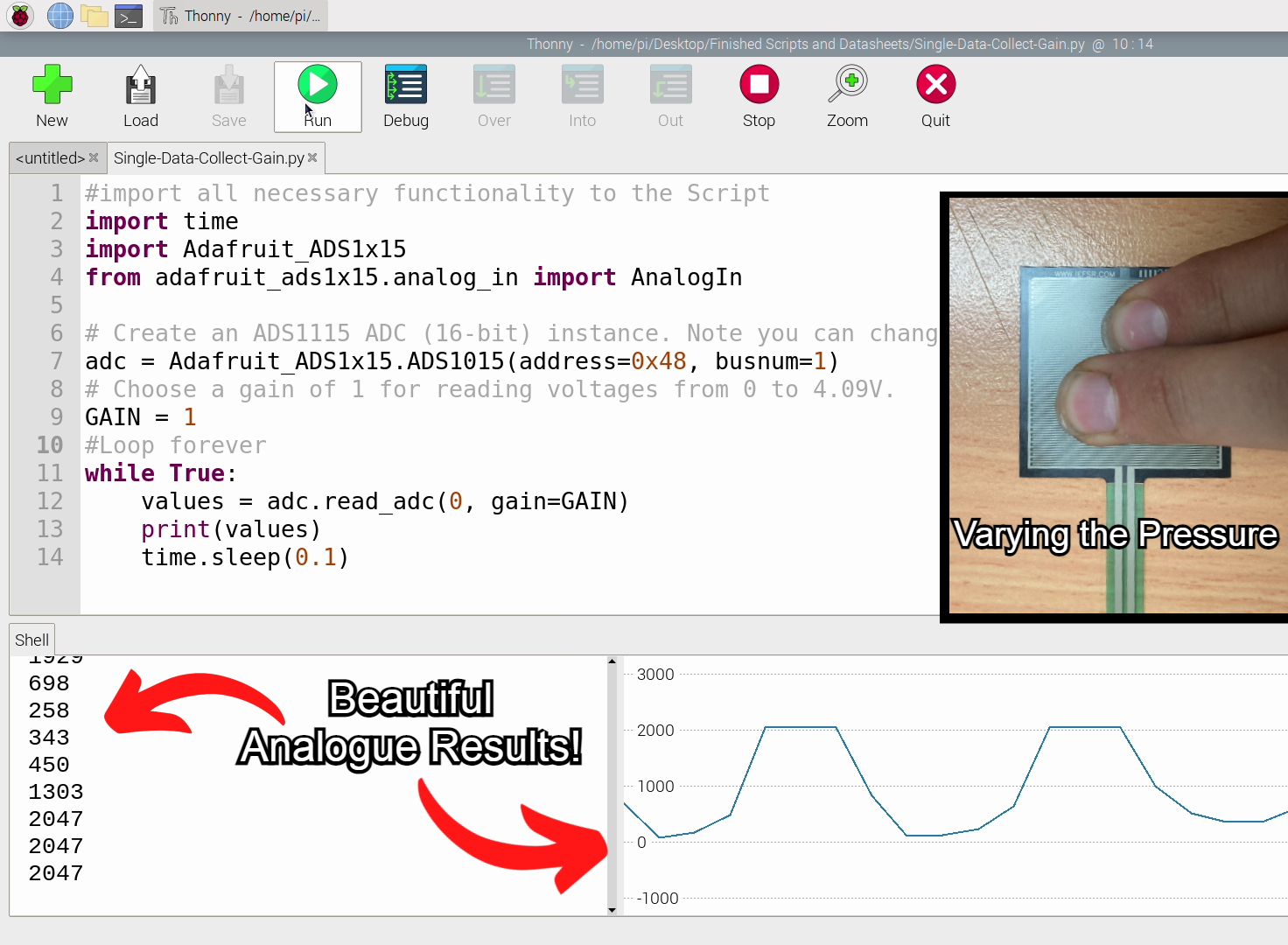
Save the above Python Script as whatever you would like (in the download zip file it is named | analogue-FSR-setup.py |) and put your system to the test by pressing the big green | Run | button! Now, whenever you press the pad it will respond with a number value (which is printed to the shell) representing the voltage traveling through the FSR Pressure Pad. When not pressed the value will be basically 0. With a huge amount of pressure, you'll get values around 2050 mV. Soften that pressure and you'll get all the values in between these two extremes. Right-click anywhere on the Shell to enable the Plotter which will easily provide you a graph of the data stream being printed to the shell. See all this happening in the image below.
Nice! So that you have all the terminology, right here we are using this Adafruit ADC in a Single Channel Mode. The other method of using this ADC is differential and you can learn more about the difference between the two methods here. I have also created a guide on using an ADC as a Differential Operation come check it linked here.
Where to Now
Naturally I had to 3D Print a Case for my Sensor Pad. Definitely increases the rugability of it and makes it more fun/easier to press down on to. See it in the image below. All Scripts and CAD designs can be found in the bottom of this page in the download section.

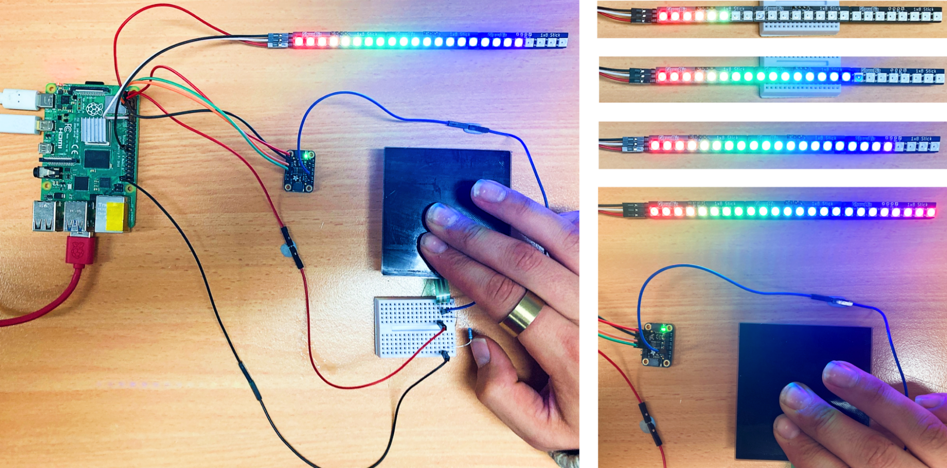
Next I had to power some hardware with my new found Analogue Control. I settled on increasing a bar of LEDs relative to pressure. Three Glowbit Stick Modules attached together make for a very effective status bar. See this operating in the image below. The script to do this can be found in the download section at the bottom of this page. If you need a hand setting up WS2812B GlowBit Stick modules come check this linked guide to learn exactly how.
Downloads and Addendum
Here is a Download Link for all the Python Scripts utilised in this guide. That Zip file also has the 3D printable Pressure Pad (FSR) Case seen in the Where to Now section of this guide and a number of relevant Datasheets. If you want ideas on what to do next with your FSR come check this great MIDI Controller that uses them!
As a final note, after this deep dive it has become apparent to me that all the FSR components in existence right now are very two-dimensional components. This is really due to the limitation of how we all make PCBs (printed circuit boards) right now. However, if we truly want to emulate our human senses and provide our robotic hands with a true sense of touch we need to start creating FSR components that are significantly more three-dimensional. Our sense fingertips are not flat and neither should our robot's sense fingers. There are Exotic 3D printers (like the Nano Dimension Dragonfly LDM) that are more than capable of 3D printing Electronic Circuits in any kind of 3D shape (the closest one to me is the Protospace at UTS). My proposal is that those machines get put to work creating FSR components that look exactly like fingertips (or spheres or any 3D dimensional shape). These robotic fingers would then have the ability to feel touch in any orientation. Breaking FSR components out of the 2nd dimension is proper ground-breaking work (bending the square FSR from above into a curved plane is just not good enough). Check below for an image of a cyborg with 2D FSR components (Tekscan).

Humans have evolved incredible dexterity and subtlety in the way they interact with the physical environment. A combination of foresight and the ability to experiment (for example, delicately touching and feeling for deflection on the target object) are two big parts of how we as humans can function so effectively. With FSR Components we can electrically emulate that experimentation that we do subconsciously every day.

