In this guide, we will be learning how to control a pump with a Raspberry Pi Pico. Whether you are pumping coolant in a project, making a DIY water fountain, or building a self-watering plant project, this guide will gear you up with everything you need to get started. We will be looking at; 2 different types of pumps that you can add to your project, how to wire them up with a motor driver, and how to program the Pico to control the pump through the motor driver.
| We also have a version of this guide for the Arduino and C++ if you want to check that out. |
Before we begin, we will be having water and conductive liquids close to electrical devices. Be extra vigilant when following along, set up your environment to minimise the impact of spills, and have a plan if a spill does occur. Let's get into it!
Should I use a Peristaltic or Submersible Pump?
There are a lot of different types of pumps out there, but for most maker projects you'll typically be looking at two main contenders – the peristaltic and the submersible pump. Each has their own strengths and weaknesses that make them suitable for different applications, so let's dive into both so you can decide which is right for your project.
Submersible Pumps
As the name suggests, submersible pumps are designed to be placed directly inside the liquid you want to pump. Once submerged and powered, they start moving water immediately. If you've ever looked at an aquarium filter or a water fountain, chances are it's using something similar to this - typically with an impeller inside that is spun by a DC motor that pushes water through.
These pumps are incredibly popular for a few good reasons:
- They're relatively inexpensive
- Simpler to use
- Often compact and light-weight
- High flow rate (they can move a lot of liquid quickly)
Some numbers for comparison, the submersible pump we will be using in this guide is on the smaller side with a flow rate of about 1.5 litres (0.4 gallons) per minute. However, you can find much larger ones that can pump more water with more pressure. Just note that the bigger pump will require more power and possibly a bigger motor driver.

However, submersible pumps do come with some notable downsides
- They must be submerged to function properly - Even if the inlet is placed into water, the pump will not be able to pull that water upwards as the pump itself needs to be full of water to operate. This also means that if any air gets into your pump, it may stop it from working and you may need to give it a little shake to get the air out.
- They're designed to be cooled by the surrounding water - This could be a positive or negative depending on how you look at it, but the liquid that flows through the pump actively cools down the motor and prevents it from overheating. However, if you run the pump out of water (or not in some other sort of liquid), or air gets into the pump, it won't be able to cool itself and will burn out if it runs for too long. Personally I once had a pond pump die on me because the water level got too low and it ran on air for a whole day.
- Unidirectional flow - Most submersible pumps can only pump water in 1 direction. Even if you reverse the polarity of the power being supplied to the motor, the water will still pump in the same direction
- Designed for low-viscosity liquids - These pumps are often designed for low-viscosity (runny or not very thick) fluids like water. If you tried to pump thicker oils or something like maple syrup, you might get no flow.
Peristaltic Pumps
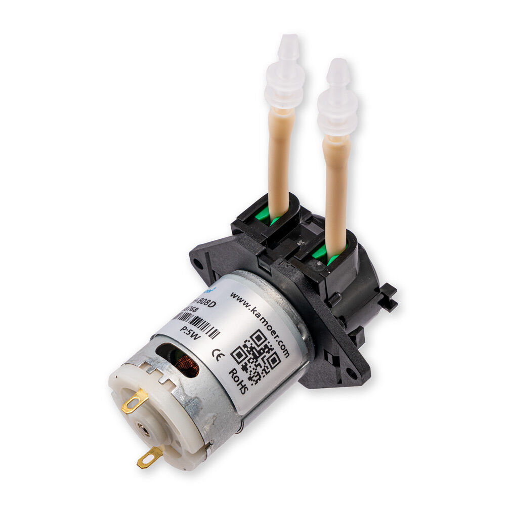
Peristaltic pumps work on a really unique principle. Imagine that had a soft tube full of liquid. If you pinched the tube with your fingers and pulled along it, you would force the water inside to flow - like how you would squeeze out a freeze pop, or pop-ice, or whatever you call them in your part of the world (or as we call them in Australia, a Zooper Dooper!). This is essentially how the peristaltic pump works, except it uses rollers spinning continuously around the tube, usually being driven by a DC motor - Wikipedia has a great GIF of it.
Let's start with the downsides of peristaltic pumps:
- They are more expensive
- Typically not water-proof
- Have a much lower flow rate
Some numbers for comparison on that last one, while our submersible pump can move 1.5 litres (0.4 gallons) a minute, our peristaltic can only pump 50 millilitres (1.7 oz) a minute.
Remember though, both of these pumps have their own unique applications and uses so let's look at what the peristaltic pump gives you for these downsides:
- Accurate and consistent pumping - Every rotation of the motor squeezes out nearly the same amount of liquid. This means that if you ran the motor for 10 seconds, and then ran it for another 10 seconds, you'll get almost the same amount of liquid each time. This makes them great for applications requiring a measured and precise amount of liquid to be pumped.
- Non-contacting operation - The mechanisms of the motor don't actually touch the liquid being pumped through. The fluid enters the motor in a tube, it is squeezed through that tube and exits out that tube. Unlike a submersible, the liquid doesn't touch any metal blades or unknown plastics that could react with your liquid. This makes them more ideal for food-safe applications or working with reactive chemicals.
- Self-priming - The peristaltic mechanism allows it to not only pump liquids, but air as well (although not efficiently, it would not make for a great air pump). This means that the inlet hose of the pump can be dipped into water (even if the hose is full of air), and when turned on, the pump will suck up water as if it were drinking out of a straw. This is known as self-priming.
- Reversible flow - You run the motor in one direction and it pumps one way, you reverse the motor's direction, and it pumps the other way - really straightforward.
So, if you're looking for a more affordable pump with a high flow rate for applications like water fountains, the submersible is probably your best bet.
On the other hand, if your project needs precise liquid measurement, food-safe operation, or the ability to pump in both directions, then a peristaltic pump would be the way to go.
Now that you have a better idea of which pump might suit your project best, let's move on to actually using them!
What You Will Need
To follow along with this guide, you'll need a few things. The components listed here are all suitable for each other but feel free to change it up and use a bigger or smaller motor or whatever your project calls for. The process will largely be the same but just keep in mind that you might need to adjust your setup depending on what you choose.
- Pump - This guide will be using these peristaltic and submersible pumps. The wiring and code used for each of these will be the same.
- Motor Driver - We will be using the Makerverse Motor Driver as it is suitable for our motors. The submersible pump uses up to 220 mA at 3-6 volts and the peristaltic uses up to 1.5 Amps at up to 5 volts - both of these are happy run off the motor driver which can supply up to 1.6 amps at 3-16 volts. If you use a more powerful hungry motor, you may need to look for a motor driver that can handle its voltage and current.
- Raspberry Pi Pico - This guide will work on any variant of the Raspberry Pi Pico. We are using a Pico 2 as it's the first one we pulled out of the draw. This guide can also be adapted to work on nearly any other microcontroller running Micopython, but we will stick to the Pico for our guide.
- Tubing - You will also need some tubing to connect to your pumps. The submersible pump we have linked comes with 1 meter (3 ft) of tubing (it is 6 mm internal diameter if you need more). The peristaltic doesn't come with any and will need some 3 mm internal diameter tubing.
- Power Supply - You will need a power supply capable of supplying the current and voltage required for your motor. For the pumps we are using, we will be able to power them off the Pico's Vbus pin. This will provide 5 volts and up to 2 Amps depending on what you plug the USB into.
- Jumper Wires and a Breadboard
Connecting the Motor Driver and Pump
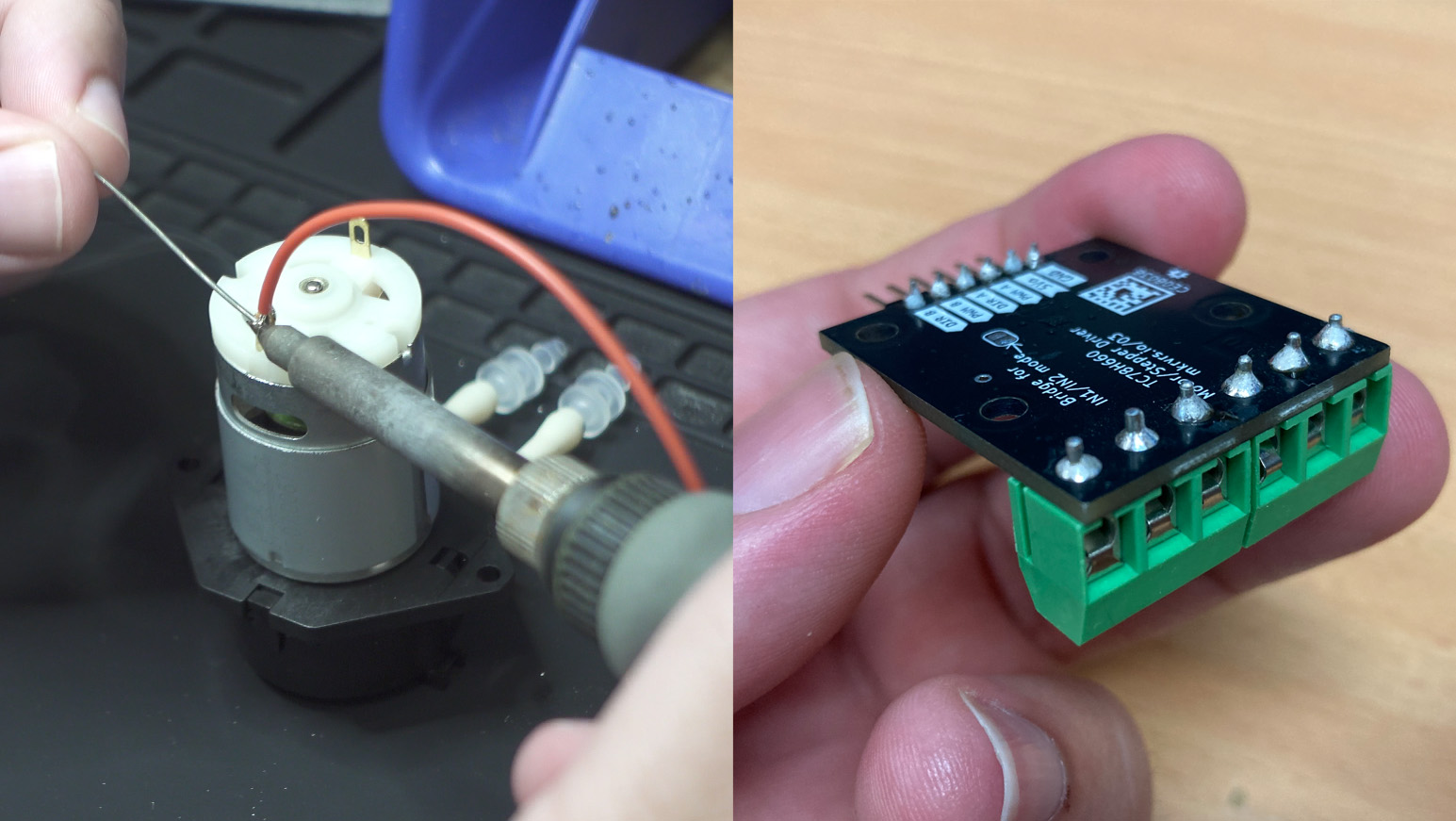
Before we start making our connections, we will first need to solder a few components. Chances are your motor driver will need its terminals to be soldered on, and your pump will need some wires attached to its terminals. If you are using a submersible pump it should already have waterproofed wires attached to it.
If this is your first time soldering, it is a lot easier than it looks and we have a guide to get you started! Just a quick tip, when soldering the wires to your pump's motor try to avoid holding the iron to it for any longer than necessary. The motor has magnets on the inside which will be damaged by heat. Don't fret about this too much, it will take a lot of heat to damage them, just don't hold the iron down on it for several minutes. As always, ensure that the wires you connect to your motor are rated to handle its maximum current. We used some 22AWG silicon wire which is good for a few amps.
Once you have your motor driver soldered up and some wires soldered to your pump's terminals (ideally wrapped with heat shrink), we can get started connecting everything.
To control the motor driver with the Pico we will need two pins; one to control the direction and another to control the speed. This should be a similar situation for other motor drivers. On the Pico, we can use any two GPIO pins to do so, but in this guide, we will be using pins 0 and 1.
Connect pin 0 of the Pico to the DIR B pin of the motor driver which will control the direction of motor B. Then connect Pin 1 to the PWM B pin of the driver which will control the speed of motor B. This motor driver can control 2 motors at once if you wish to use another one, just repeat all of these steps for motor A.
We will also need to connect the ground pin of the motor driver to a ground pin of the Pico. This ensures that they can both have a shared reference of what 0 volts is.

Now let's connect our motor to the driver board. Using a flat-head screwdriver, secure the wires of the motor to the screw terminals of the motor driver. These do not need to be extremely tight, just nip them up tight enough to hold the wire in place. Extensive overtightening can break the terminals. Also ensure you match the polarity of the motor to that on the driver board. Don't worry if you get this wrong as the motor will just move in reverse. You can swap back the terminals to fix this, or just change it in code.
We are also going to plug in our power supply to the VM and ground terminals on the motor driver. As always ensure that the wires you use to connect your power supply to the motor driver board are rated for the current that the motor will draw. Although this motor can draw up to 1.5 Amps, we found that in day-to-day use it only consumed a maximum of 0.5 Amps. If you pump a liquid thicker than water, you may draw more current. We are only pumping water in this example so we are able to get away with using some jumper wires to connect our power supply. Note that the jumper wires we are using are the thicker, lower gauge kind that can handle up to 1 Amp.

This also makes it easy to plug into the Pico to source power from it. To do so we will connect the Vbus pin to the VM terminal of the driver, and a ground pin to the Ground terminal of the driver. To connect the jumper wire to the screw terminal, we cut one end off the wire and stripped the protective layer off to give us something to screw into.
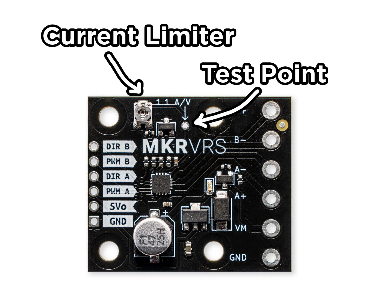
One more quick tip here. The Makerverse Motor Driver comes with current limiting capabilities which can be controlled by the little screw potentiometer on the top of the board. With a small screwdriver, gently rotate the screw clockwise until it reaches its limit. From its maximum position, rotate it the other way (counter-clockwise) 1/4 of a turn. This position should set the maximum current of the motor to about 1 Amp - just some nice peace of mind that you won't draw too much with your motor.
If you have a multimeter you can precisely set this to whatever maximum current you like. Measure the voltage from ground to the test point labelled 1.1 A/V. Divide that voltage by 1.1 and you will get the maximum current the board will allow.
E.g. if you rotated the potentiometer and read 1.43 volts, 1.43 / 1.1 = 1.3. The maximum current will be set to 1.3 amps. You can set this as high or low as your project needs.
Coding the Pico and Running the Motor
Now with this all wired up, we can program our Pico to control the motor driver and with it the pump. Plug your Pico into your computer, select its com port and paste in the following code. If this is your first time using the Pico with Thonny or you just need a refresher, we have a short guide that's part of a full Pico course.
from machine import Pin, PWM
import time

# Set up the direction pin (on/off digital output)
dir_pin = Pin(0, Pin.OUT)

# Set up the PWM pin for speed control
pwm_pin = PWM(Pin(1))
# Set the pin frequency (this is not duty cycle)
pwm_pin.freq(1000)

# Easier to use this variable than manually type it
max_pwm = 65535


# Main loop
while True:
    # Set direction forward
    dir_pin.value(1)
    # Set motor speed to 100%
    pwm_pin.duty_u16(max_pwm)
    time.sleep(5)

    # Set motor speed to 0%
    pwm_pin.duty_u16(0)
    time.sleep(2)


    # Set direction reverse
    dir_pin.value(0)
    # Set motor speed to 100%
    pwm_pin.duty_u16(max_pwm)
    time.sleep(2)


    # Set motor speed to 0%
    pwm_pin.duty_u16(0)
    time.sleep(2)
Lets take a quick look at what this code is actually doing by breaking it down. First of all it imports needed pin and time libraries:
from machine import Pin, PWM
import time
Then we set up Pin 0 as a regular digital output. The direction pin that this is plugged into is simply looking for a high/low signal to set the direction of the motor. We also set up Pin 1 as a PWM output. The motor driver pin that this is connected to will use this PWM to set the speed of the motor. In MicroPython we cannot simply set a percentage for out PWM and instead have to set a number between 0 and 65,535. To make this easier, we then define a variable of this maximum number so we don't need to keep typing it.
# Set up the direction pin (on/off digital output)
dir_pin = Pin(0, Pin.OUT)

# Set up the PWM pin for speed control
pwm_pin = PWM(Pin(1))
# Set the pin frequency (this is not duty cycle)
pwm_pin.freq(1000)

# Easier to use this variable than manually type it
max_pwm = 65535
Then we enter our forever looping while true loop. Here we start by setting Pin 0 to high (or on / 3.3 volts, however you want to describe it), and we set the maximum possible PWM on Pin 1. This is going to drive our pump forward as fast as we can. We then sleep the Pico for 5 seconds which will run the pump for 5 seconds.
# Main loop
while True:
    # Set direction forward
    dir_pin.value(1)
    # Set motor speed to 100%
    pwm_pin.duty_u16(max_pwm)
    time.sleep(5)
Then we set the PWM to 0 for 2 seconds - this will stop the pump. After that we set pin 0 to low or off, and the PWM back to maximum - this will run the motor in reverse for 2 seconds. Then we stop the motor again for a few seconds.
    # Set motor speed to 0%
    pwm_pin.duty_u16(0)
    time.sleep(2)


    # Set direction reverse
    dir_pin.value(0)
    # Set motor speed to 100%
    pwm_pin.duty_u16(max_pwm)
    time.sleep(2)


    # Set motor speed to 0%
    pwm_pin.duty_u16(0)
    time.sleep(2)
Run this code and your pump should start! To test ours we connected some tubing and set up some cups of water. We placed one tube into each cup, ran the code and saw that the pump was moving water from one to the other.
The code above pumps forward for 5 seconds, then backwards for 2 so the water should eventually move from 1 cup to the other. If you don't know which hose is the inlet, and which is the outlet, you can submerge them both and one will start blowing bubbles - this is your outlet.
From here you can modify this code and apply it however you need in your project.

And for the sake of completeness, we also went ahead and gave the submersible pump a go. As the set-up is compatible with both pumps, we could swap the peristaltic out and screw in the submersible.
If you run the same code you may find a weird quirk of this pump type. As the motor runs forward for 5 seconds it will pump into the other cup. But as the motor runs in reverse for 2 seconds, it will also pump water forward into the other cup. This is due to how this pump operates, but ensure that you are pumping it forward as it will likely be less powerful running the pump in reverse.

Where to Next?
And with that, we now have the skill to control a pump and add it to our projects however we see fit. If you are looking for a project to apply this in, we have an entire project called Plant_io. Its a kit containing everything you need to get started to build your own self-sustaining automatic plant watering device. We are pretty darn proud of this project and have some nice guides on it as well that let you add sensors to it as you desire.
If you are using the submersible pump, or you are only interested in using the peristaltic in 1 direction, you might be interested in checking out how to use a relay. It's an electrical switch and is another method of controlling a pump. You also might be interested in checking out how to use a MOSFET which can do the same job but also with speed control. We used a motor driver in this guide as it is more robust, but your project may be better suited for one of these.
If you use any of this to make something cool, or you need a hand with anything we covered here, feel free to drop a comment in the forum topic for this guide below. We are all makers at Core and happy to help.
Till next time, happy making!

