In this guide, we’ll learn how to harness the power of MOSFET transistors to easily control higher-powered components like solenoids, motors, and Peltiers with a microcontroller. First, we will cover an easy-to-follow example using simple components, then we will dive into wiring up some of these higher-power components.
Hardware mentioned in this guide:
Contents:
- Transistors as Digital Switches
- Choosing a Transistor
- Wiring up a Transistor as a Switch
- Programming the Microcontroller
- Example 1: Controlling a Headlight
- Example 2: Controlling a Solenoid
- Example 3: Controlling a Motor With PWM
- Other Types of Transistors
- Aside: Gate Voltage
- Conclusion
Transistors as Digital Switches
The digital pins of a microcontroller are only capable of supplying a few milliamps of current at 3 to 5 volts, so if we wish to control higher-power components (that might require a few Amps of current at much higher voltages) we will need to use something like a transistor.
The digital pins of a microcontroller are only capable of supplying a few milliamps of current at 3 to 5 volts, so if we wish to control higher-power components (which might require a few Amps of current at much higher voltages) we will need to use something like a transistor.
Transistors can be used in a variety of ways, but we will focus on their use as electronically controllable switches. There is a wide range of transistor types to choose from, but for this guide, we will just stick with an N-channel MOSFET, as the setup we will provide with this type of transistor is extremely common and robust.
A MOSFET has 3 pins: the gate, drain, and source. By changing the voltage at the gate pin, we can control the flow of electricity between the drain and source pins. If we supply 3.3 or 5 Volts to the gate pin we allow current to flow between the other 2 pins. And if we set the gate pin to 0V, we don't allow current to flow and the transistor acts as an open switch.
This means we can wire a MOSFET into a circuit like a switch, then by supplying 3.3 or 5 Volt logic, we can control higher-powered components on this circuit with a microcontroller.

This is the standard pinout of an N-channel MOSFET.
Choosing a Transistor
Let’s quickly go over 3 key factors to consider when choosing a transistor to act as a switch:
- Drain-Source Voltage: This is the maximum voltage that we can safely switch without damaging the MOSFET. Generally, datasheets will specify an "absolute maximum" and of course, it's always best to stay below this value with some safety margin.
- Continuous Drain Current: This is the maximum amount of current that can safely flow through the MOSFET continuously.
- Gate Threshold Voltage: When the voltage on the gate pin reaches this threshold voltage, the MOSFET starts allowing current to flow. If the voltage is lower than this threshold, the MOSFET won't let current pass through. For the transistor to be "fully-on" the gate voltage needs to be higher than this value - by how much is a case-by-case... and a conversation for another time.
For this guide, we will be using the P30N06LE MOSFET, a very common MOSFET that is suitable for a wide range of applications. With a drain-source voltage of 60V and a continuous drain current of 30A, it is beefy enough to power most components you will encounter with plenty of headroom to spare. Its gate threshold voltage lies somewhere between 1 and 2 Volts (not every MOSFET comes out of the factory the same), but the digital logic from most microcontrollers alternates between 0 Volts and 3.3 or 5 Volts, which aligns perfectly with this MOSFET's gate threshold voltage range. We often refer to MOSFETs with such characteristics as "logic-level MOSFETs" since they're happy to be switched by 3.3-5V signals.
Note: These big beefy MOSFETs can get very hot, very quickly. Although this MOSFET is rated up to 30A of continuous current, it may only be able to handle this with adequate cooling. Without using something like a heatsink, we may only be able to achieve 5-ish Amps of continuous current.
Mosfets also come in smaller and cheaper varieties such as the 2N7000. Whilst this one is only rated to about 100 milliamps, it is still rated for up to 60 Volts. This may be useful if for example you are switching a relay, or driving some 12V LEDS at only a few milliamps, and don't need to use bulky and more expensive MOSFETs.
There are also inexpensive and ready-to-use MOSFET modules that remove a lot of the setup hassle that we will see in later examples.
Wiring up a Transistor as a Switch
The best way to learn is through examples, so let's dive straight into an easy one - switching an LED. The LEDs we are using don't require much power and could very easily be powered directly from the microcontroller's pins. However, this basic setup is a good starting point as it is easy to follow along using a breadboard and jumper wires and also mirrors the same circuit layout you would use for more power-hungry components.
Let's introduce some terminology. Over the next few examples, we will refer to the component we wish to power as a "load". In this case, our load is the LED and accompanying current-limiting resistor.
Need a refresher on LEDs and current limiting resistors? Check out our guide.

At the top, we have an LED and resistorin series, and we can treat the component we are trying to control as a "load" in our circuit.
If we call the component we wish to control a load, we can use a set of nice universal instructions for wiring up a MOSFET as a switch:
- Connect the MOSFET's source pin to ground (or the negative terminal of our voltage supply).
- Connect the MOSFET's gate pin to a microcontroller output pin.
- Connect the load from the positive terminal of the power supply to the MOSFET's drain pin.
That might be a little hard to decipher so let's wire up our LED and resistor load. Any microcontroller running at 3.3 or 5 Volts will work but for these examples will be using a Raspberry Pi Pico.
First, we will need to get some things set up before we hook up our MOSFET.
For this example, we are going to source power from the Pico itself. Usually, we would use an external power supply that is capable of driving the power-hungry components we wish to control, but for the sake of simplicity we will:
- Connect the breadboard's V+ power rail to the Pico's Vbus pin.
- Connect the breadboard's ground rail to one of the Pico's ground pins.
By doing so, we can now treat the V+ and ground rails as if they are an "external power supply" which we will be using to power the LEDs off.
And finally, we will set up our load by connecting our LED and current limiting resistor (470 Ω) in series (we are not plugging them into the circuit yet, just placing them on our board).
Note: Only when the Pico is plugged into the computer (or other USB power source), will the VBUS pin provide 5 Volts.
Let's start with our first step:
- Connect the MOSFET's source pin to ground (or the negative terminal of our voltage supply).
We can achieve this by popping our MOSFET in the board and connecting the source to the breadboard ground rail.
Ensure that your MOSFET is not backwards and is in the correct orientation as shown in the image on the right.
Now lets:
- Connect the MOSFET's gate pin to a microcontroller pin.
Simply connect the gate pin to the Pico's GP15 pin, then connect a pull-down resistor (1 to 10 kΩ) to the breadboard ground rail.
Note: This pull-down resistor isn't actually a part of the transistor setup. Its purpose is to prevent the voltage from the microcontroller pin from drifting or 'floating'.)
And finally, we will:
- Connect the load from the positive terminal of the power supply to the MOSFET's drain pin.
This means we need to connect the breadboard's V+ rail to one side of the load, and then the other side of our load to the MOSFET drain pin.
And with that, we have successfully wired up our MOSFET as a switch!
Warning: We are going to be plugging the Pico and this circuit into a computer. Incorrect wiring has the potential to damage your PIco and computer. Double-check that your circuit is wired up in the same manner as the completed one on the right.
Programming the Microcontroller
Now we have a circuit wired up, but nothing interesting will happen until we set some voltages on the MOSFET gate pin with the Pico. We will be using Thonny IDE to program our PIco. If you need a refresher on how to do so, check out our guide.
So, plug the Pico into your computer, open up Thonny and copy-paste the following code into a new script:
from machine import Pin
import utimeMOSFET = Pin(15, Pin.OUT) # Initialise the pin that is connected to the gate pin of the MOSFET
while True: # Loop forever
MOSFET.value(0) # Turn the MOSFET ON
utime.sleep_ms(1000)
MOSFET.value(1) # Turn the MOSFET OFF
utime.sleep_ms(1000)
from machine import Pin
import utime

MOSFET = Pin(15, Pin.OUT) # Initialise the pin that is connected to the gate pin of the MOSFET

try:
    while True:  # Loop forever
        MOSFET.value(0)  # Turn the  MOSFET OFF
        utime.sleep_ms(1000)
        MOSFET.value(1)  # Turn the MOSFET ON
        utime.sleep_ms(1000)

except KeyboardInterrupt:
        MOSFET.value(0)  # Turn the  MOSFET OFF
This script is pretty straightforward and is just going to continuously set the GP15 pin to 3.3 Volts for 1 second then to 0 Volts for a second.
The try: and except: part of the code:
try:

(something something)

except KeyboardInterrupt:
        MOSFET.value(0)  # Turn the  MOSFET OFF
Ensures that when we stop the script from running, it returns the pin to 0 volts so we don't accidentally leave our load running.
Save the script to the Pico and Run it – If everything is working you should see the led turn on and off every second, Congrats!
If your LED isn't turning on, double-check your wiring and try reversing your LED, it has a polarity and only works one way.
Whilst you may have seen microcontrollers blinking an LED on and off many times before, there is something cooler going on here. And that is that the power being supplied to run our "load" is not coming from the GP15 pin of the pico, but is coming from an "external" power source, yet the GP15 pin is controlling as if it were.
So now we know how to do this, we can have some fun and start controlling some loads that need more power than a hundred Picos could supply!

Our Pico, LED load and transistor wired up and coded.
Example 1: Controlling a Headlight
Now let's see the robustness of this set-up in action by controlling some higher-power loads like an incandescent car headlight. In terms of circuit layout, this is going to be the same as before, but now we have an introduced hurdle of dealing with the 60 Watts that the headlight requires. This involves employing an appropriate power supply, as well as ensuring our wiring can handle the 5 Amps the headlight will draw (our jumper wires and breadboard are only good for 1 Amp or so).
This is where the guide becomes a little more involved to replicate yourself, and if you do so just be wary as we are dealing with higher current circuits meaning we can much more easily burn out wires and start fires. So always be vigilant, check your circuits before powering anything on, and ensure your wiring is rated for the currents you will pass through it.
To make it easier to hook up our circuit, we have soldered a 3-pin screw terminal to our transistor as shown in the image on the right.
If you wish to make things even easier, there exists a MOSFET switch module that comes with screw terminals pre-installed and makes wiring up these higher-powered loads much simpler.
A 3-pin screw terminal soldered to our MOSFET to make wiring easier.
This time we will be sourcing power from a benchtop power supply and this brings with it an extra step. We will need to ensure that the Pico and the bench power supply share a common ground as without this we may run into some issues.
So to achieve this we will connect the ground pin of our pico (which we have connected to the ground rail of the breadboard) to the ground of our benchtop power supply and we can use jumper wires for this as there will be little current flowing through this connection.
Now we can follow our wire-up steps again so let's:
- Connect the MOSFET's source pin to ground.
Ensuring we use wire rated for the current our load will use.
Exactly the same as last time we will then:
- Connect the MOSFET's gate pin to a microcontroller pin.
We will again be using the GP15 pin. We can use jumper wires for this as well as the power for the load won't be coming from the Pico.
We have also placed our pulldown resistor on the breadboard (again 1 to 10 kΩ will do).
And finally, we will:
- Connect the load from the positive terminal of the power supply to the MOSFET's drain pin.
We will obviously need to use the higher current-rated wire to connect our headlight from the positive terminal of the power supply to the drain pin.
If you look at our circuit, we are placing the MOSFET between the ground and the load, this is called low-side switching (just a bit of helpful terminology).
Warning: We are again going to be plugging the Pico and this circuit into a computer. Incorrect wiring has the potential to damage your PIco and computer. Double-check that your circuit is wired up in the same manner as the completed one on the right.
For this example, we will be using the same code as before which will work exactly the same as long as we have used the same GP15 pin.
So, plug in the Pico, open the script again, hit run and this time our headlight turns on and off every second just like our LED. But now we are controlling a load of 12 Volts at nearly 5 amps, all from the humble pin of a microcontroller.
Example 2: Controlling a Solenoid
Now that we have a circuit set up for higher-power loads, we can simply swap the load out for another and as long as the power supply is suitable, we will have no issues.
This time we will be using a solenoid as our load, but for this, we will need to incorporate a flywheel diode. You don't need to worry too much about this as it is part of the load and is used for protection in circuits that involve inductive loads such as motors and solenoids.
So we will wire up our circuit by connecting the new solenoid and diode load from the positive of our voltage supply to the drain pin. Then using the same code on the Pico, we should again see the solenoid actuate every second.
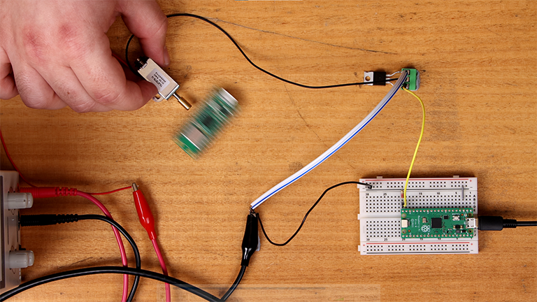
This is a freeze frame of our solenoid kicking around a Pico board.
Example 3: Controlling a Motor With PWM
Let's do one more example with a motor, but so it doesn't get boring we will spice this up with some PWM.
We will swap out our solenoid load with the motor (and accompanying flywheel diode), and then using the same code, when we plug in our Pico we should see that the motor powers on and off every second.
If you've played around with DC motors before you have likely encountered motor drivers. Take a closer look at one next time and you might spot some transistors on it. These drivers typically utilise transistors like we are doing so here, but with a bit of clever circuit design, they allow for the motor's direction to be reversed.

Another freeze frame of a motor connected to our circuit, spinning.
Now let's spice things up. A MOSFET can switch fast... really fast. This means we can pass a PWM signal from the pin of our microcontroller to the transistor and it will be able to switch our power supply with the same PWM signal.
Using the same setup, we are going to plug in the Pico, open up Thonny, then paste the following code into it:
from machine import Pin, PWM
import utime

MOSFET = PWM(Pin(15))  # Initialize a PWM object on the pin that is connected to the MOSFET gate

MOSFET.freq(1000)  # Set the PWM frequency to 1 kHz

try:
    while True:
        # Ramp up from 0 to full duty cycle
        for duty in range(0, 65536, 655):  # Iterate through duty cycles from 0 to 65535 in increments of 655
            MOSFET.duty_u16(duty)  # Set the duty cycle of the PWM output
            utime.sleep_ms(10)  # Wait for 10 milliseconds before incrementing the duty cycle

        utime.sleep_ms(1000);

        # Ramp down from full duty cycle to 0
        for duty in range(65536, 0, -655):  # Iterate through duty cycles from 65535 to 0 in decrements of 655
            MOSFET.duty_u16(duty)  # Set the duty cycle of the PWM output
            utime.sleep_ms(10)  # Wait for 10 milliseconds before decrementing the duty cycle

        utime.sleep_ms(1000);

except KeyboardInterrupt:
    MOSTFET.duty_u16(0)
This code is very straightforward. It cycles the PWM duty up from 0 to full over 1 second, then holds it there:
    # Ramp up from 0 to full duty cycle
    for duty in range(0, 65536, 655):  # Iterate through duty cycles from 0 to 65535 in increments of 655
        MOSFET.duty_u16(duty)  # Set the duty cycle of the PWM output
        utime.sleep_ms(10)  # Wait for 10 milliseconds before incrementing the duty cycle

        utime.sleep_ms(1000);
And then it ramps down from full duty cycle to 0 over 1 second, then holds it there:
    # Ramp down from full duty cycle to 0
    for duty in range(65536, 0, -655):  # Iterate through duty cycles from 65535 to 0 in decrements of 655
        MOSFET.duty_u16(duty)  # Set the duty cycle of the PWM output
        utime.sleep_ms(10)  # Wait for 10 milliseconds before decrementing the duty cycle

        utime.sleep_ms(1000);
Save the script to the Pico and Run it – If everything is working you should now see the motor ramping up and down as a result of our PWM cycle. Like before, we can use this same PWM code to power anything that can be controlled with a PWM. Feel free to try it on our initial LED example and you should see the same PWM cycle as the motor!
Other Types of Transistors
So far we have only talked about N-type MOSFETs, but there are many other types of transistors available. Transistors can be complex, so without diving into too much theory let's touch on some other types you may encounter and what applications they may be more appropriate in.
P-type MOSFETs
P-channel MOSFETs are very similar to N-channel MOSFETs but behave a little differently. In the opposite fashion to an N-channel, the gate voltage that we are supplying with our microcontroller must be higher than the voltage we are switching. This means a P-channel MOSFET cannot control a 12 Volt circuit with a 3.3 Volt signal. But what this does mean is that we are able to easily switch a negative power source, so we could switch a -12 Volt circuit with a 3.3 Volt signal, something an N-channel cannot do (as the N-channel needs a gate voltage to be lower than the circuit voltage). Additionally, whilst we place an N-channel between ground and the load, we place a P-channel between the positive Voltage and the load. This is called high-side switching and is sometimes sought after in circuit design.
BJT Transistors
We have been talking about MOSFETs but another type of transistor is the BJT (bipolar junction transistor). BJTs are often used in other than applications than switching (such as in amplifier circuits) but can still very easily be used as a switch. BJTs also utilise another naming convention for its pins: the base, emitter, and collector, and like MOSFETs also come in 2 types, NPN and PNP (similar to N-channel and P-channel). As we've seen, to "flick" the MOSFET as a switch we need to supply a voltage to one of its pins, but when using a BJT we will need to supply a current instead. BJTs are also often a little cheaper than MOSFETs.
Relays
While not a transistor, a relay is another form of switch that we can use in a very similar fashion and you can check out our guide on how to do so. Relays typically contain an internal mechanical switch that is flicked when a voltage is supplied. However, this means that they are a little less responsive as a physical mass needs to be moved around inside the relay, and that we cannot use PWM signals nor switch our circuits very fast as this would wear out the relay. But what relays do offer is better electrical isolation (as there is a physical separation in the circuit when switched open) and the ability to switch AC power much easily as transistors are more suited for controlling DC power.
Aside: Gate Voltage
We thought we should quickly touch on another important aspect of gate voltage now that we have a bit of knowledge about MOSFETS. We have already talked a bit about gate threshold voltage, however, when we cross this voltage the MOSFET doesn't completely "switch on", but starts to switch on.
The graph on the right is pulled from our MOSFET's datasheet. The axis on the bottom is the voltage on the gate pin that we would be setting with our microcontroller (it's actually the voltage between the gate and the source pin, but remember we wire our source to ground in this switch circuit). As we can see at 3.3 volts the MOSFET isn't "fully on" and is only capable of allowing a bit over 10 Amps of current to pass between the drain and source pins. We can also see that if we were to supply 5 Volt logic to the pin, we would be able to pass through 50 amps (but also remember our MOSFET has a 30 Amp continuous rating).
Additionally, the higher this gate voltage, the less resistance there is between the drain and source pins - meaning your MOSFET will consume less power, have less of a voltage drop across it, and will also stay a bit cooler.
Just a little more important information to know when dealing with MOSFETS.

Conclusion
The sky is the limit to what you can control with your microcontroller. If you've got a MOSFET and power supply big enough to drive your load, you can control it, and this is such an incredibly powerful tool to have as a maker. If you make something cool with this MOSFET circuit, please show us on our forums, and if you have any questions or need some help, start the conversation below. We're full-time makers and happy to help.
Happy Making!

