In this guide, we'll learn what a Relay is, why we might use one, how to choose a Relay, and finally how to use one with a Raspberry Pi Pico.
To follow along you'll need:
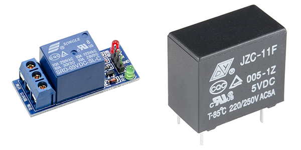
- A 5V SPDT Relay - I'll be using a 5V Single Channel Relay Module.
- An LED and current limiting Resistor - we have a handy LED and Resistor Pack that can get you hooked up.
- Optionally, A 12V DC Device and Power Supply - such as a 12V Blower Fan, a 12V Plugpack, and a Barrel Jack Adapter.
- A Raspberry Pi Pico.
- A way to connect them all together, I'll be using a Breadboard and some spare hookup wire.
Note: Not all Relays are compatible with the Raspberry Pi Pico or other 3.3V devices. The 5V Relay Module we are using is compatible with 3.3V power and logic. If you are following along with a different Relay, please check the product page/datasheet to confirm it is 3.3V compatible and that it will work with this guide.
If this is your first time using a Raspberry Pi Pico we also recommend that you check out our guide on how to Setup a Raspberry Pi Pico and Code with Thonny.
Contents:
Introduction
Have you ever wanted to control a higher-powered device from a low-powered microcontroller, such as a 12V fan from a 3.3V Raspberry Pi Pico, without frying the microcontroller?
One of the easiest ways is to use a Relay!
What Is A Relay?
Relays are a type of switch that can be turned on and off electronically. Internally they are actually made up of two physically and electrically separated circuits: the input circuit, which does the switching, and the control circuit, which is what gets turned on and off.
They are worked by sending an electrical signal to the input circuit - this will usually be from your microcontroller. The input circuit in turn causes the control circuit to activate, which turns on whatever you have attached to the control circuit.
Did you notice I mentioned that the input and control circuits are physically and electrically separated? Then how does the input circuit activate the control circuit? It's not done with magic, but rather using either magnetism (in Electromechanical Relays) or light (in Solid State Relays). Note there are other types of Relays, such as Reed, Coaxial, and more - but Electromechanical and Solid State are by far the most common types.
Relays can also do more than just connect or disconnect a single path of electricity: they come with different combinations of 'Poles' and 'Throws' which enable you to do interesting things when the input circuit is or is not activated - such as toggle between devices, or even completely invert the polarity or an entire circuit!
Poles
The number of Poles a Relay has defines how many switches there are in its control circuit.
A Single Pole Relay has one switch, and a Double Pole has two switches.
A Single Pole will let you switch only one device on/off, but a Double Pole will let you switch two devices on/off simultaneously.
Note that Poles cannot be controlled independently, they are both controlled by the same single input signal.
Throws
The number of Throws a Relay has (or more specifically a Pole has) defines how many output contacts each Pole in the Relay can switch between.
A Single Throw has one output contact per Pole, and a Double Throw has two output contacts per Pole.
A Single Throw can only switch its single contact from on to off and back again, whereas a Double Throw will alternate between its two contacts when the Relay is on or off. When Contact A is turned off, Contact B gets turned on, and when Contact A gets turned back on, Contact B gets turned back off.
Pole/Throw Combinations
We combine the Poles and Throws of a Relay together to define its Pole and Throw configuration, such as:
- Single Pole Single Throw - SPST for short
- Single Pole Double Throw - SPDT
- Double Pole Single Throw - DPST
- Double Pole Double Throw - DPDT

The contacts on a Double Throw Relay use the following terminology to describe the function of the contact:
- Normally Open (or 'NO') - When the Relay is not powered or not activated, this side of the control switch is an Open Circuit with the Common Contact. A device connected to this contact will be OFF by default.
- Normally Closed (or 'NC') - When the Relay is not powered or not activated, this side of the control switch is a Closed Circuit with the Common Contact. A device connected to this contact will be ON by default.
- Common (or 'C') - When the Relay is not powered or not activated, the NC contact is connected to this contact. When the Relay is activated the NO contact is connected to this contact.
Why Use a Relay?
So we have an understanding of what a Relay is, why would we want to use one?
First of all, the fact that the input and control circuits are physically and electrically separate gives Relays a superpower: being able to turn on and off high-powered devices from a much lower-power device - without frying the lower-power device!
In practice, this means we can use something small like a Raspberry Pi Pico to control things that need a lot of juice to run, such as a fan/motor or water valve/solenoid, that we otherwise simply could not do so safely.
I'm assuming you are not a qualified Electrician. While many Relays can control 240VAC or "Mains Power" - it is NOT safe for you to do it. Working with Mains Power can be fatal - do not attempt to manipulate Mains/240VAC power, with a Relay, or for any other purpose.
In addition to controlling higher-powered circuits, you can also use a Relay to take advantage of its Pole/Throw combinations, for example:
- You could use an SPDT Relay to toggle between devices - such as powering a pump when under normal conditions, but when a fault is detected cutting power to the pump and moving power to an emergency siren instead.
- You could use a DPST Relay to switch two independent circuits at the same time - such as turning on and off a grow light and a heated bed for a micro-greens garden.
- You could use a DPDT Relay to swap the direction of current in a circuit - such as changing a motor from forwards to reverse!
While Relays have a very useful place in electronics, it can be good to know when to consider using a different type of switching device - such as a Transistor or a MOSFET.
- If you need high-speed switching - Relays are relatively slow to turn on and off.
- If space on your circuit board is limited - Relays take up a lot more space than other components.
- If silence is an absolute must! Electromechanical relays can be a bit noisy when switching.
- If you just need to switch something on and off, and, that thing:
- is the same voltage as your microcontroller, in most cases, a Transistor will do just fine.
- is a higher DC voltage and sharing a common ground is safe, in most cases, a MOSFET will do just fine.
How To Choose A Relay?
Now that we've decided a Relay is the right device for our project, it's time to get the right one. There are a few factors to consider when choosing a Relay.
Input Power
First, we need to consider what input voltage the Relay requires to be activated and if your circuit can provide the required voltage to it. Most DC Relays available to makers come as either 5V or 12V input voltages.
If you are using a 5V or 3.3V microcontroller, such as an Arduino or Raspberry Pi Pico, you will have an easier time working with a 5V Relay over a 12V Relay.
Furthermore, if you are using a 3.3V microcontroller, you must check that your relay is compatible with 3.3V power and logic, which you can find on the product page or datasheet of your relay. If it only mentions 5V, then it is safest to assume that it cannot be used with a 3.3V microcontroller.

Control Power
Next, we need to consider the maximum Voltage and Current of the control circuit in the Relay. This is sometimes referred to as the 'Contact Rating' or how much the Relay can "Drive".
You need to select a Relay that's maximum is higher than your load. For example, a Relay that can drive up to 5A @ 30VDC will not be suitable for a 12VDC circuit that is expected to have an 8A load, as the load of 8A is more than the maximum of 5A.
On a side note, electricity starts to move from the dangerous to very-dangerous category between 12V and 30V upwards, so also consider if you should be controlling the circuit or device in the first place.
Pole/Throw Configuration
We've already covered the differences between Pole and Throw combinations in the previous section, but for a quick refresher:
- Use an SPST Relay if you only need to switch on/off a single circuit.
- Use an SPDT Relay if you need to toggle between circuits.
- Use a DPST Relay if you need to switch on/off two circuits simultaneously.
- Use a DPDT Relay if you need to toggle between two different circuits simultaneously.
Standalone vs Module
Finally, if you're just starting out with Relays I recommend getting one that comes as a Module, such as the one I'm using in this guide.
A module will make it easier to connect the Relay to your microcontroller and come with the necessary circuitry required to switch the Relay on from your microcontroller.
If you want to use a standalone/non-module Relay, check out the section below that shows what other components you'll need and how to wire one up to a microcontroller.
How To Use A Relay?
Let's have a look at how to actually use a Relay with a Raspberry Pi Pico.
Connecting up a Relay involves wiring the Input Circuit to the Pico, and wiring the Output Circuit to the device to be controlled. To begin with, we're going to control the LED.
Input Circuit
Since we're using a Module, it is very simple to connect the Relay to the Raspberry Pi Pico.
Connect the following 3 pins of the Relay Module to the corresponding pins on the Pico:
- Relay VCC -> Pico 3V3V
- Relay GND -> Pico GND
- Relay IN -> Pico GPIO 16
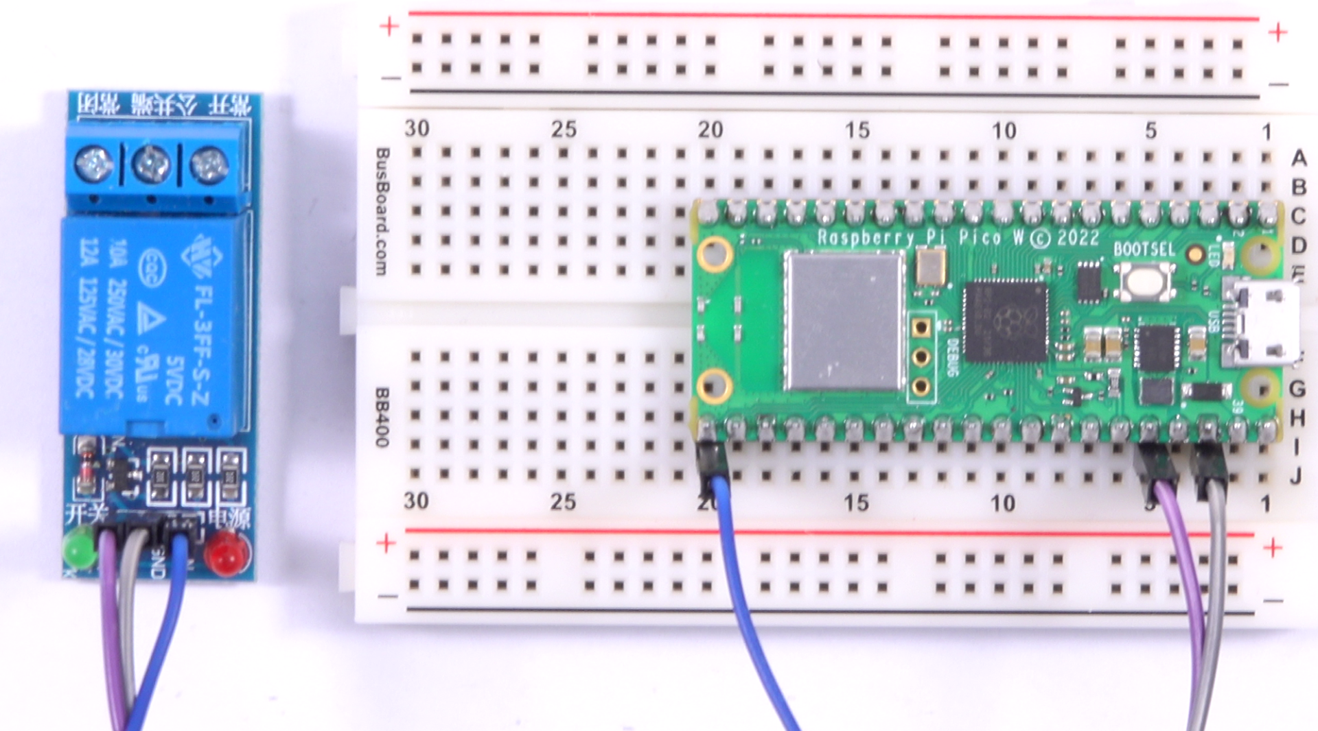
Click to open full-size image
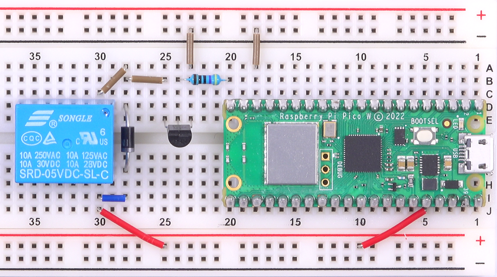
If you're using a Standalone Relay you will need a few extra components to safely activate the Input Circuit of the Relay.
You will need the following components:
- An NPN Transistor
- A current limiting Resistor - a 470 ohm from the LED Pack will do just fine
- A Schottky Diode - the General Purpose 1N4001 works fine
Refer to the image on the right for how to connect these together. A few points to note:
- The Relay IN pin is connected to GPIO 15 (instead of 16 in the section above). If you use this pin as well, don't forget to change the pin number in the example code below accordingly.
- The Relay is not driven directly from the GPIO pin of the Pico - it requires too much current to safely activate from GPIO, so instead a transistor is used.
- The Diode is used in reverse position as a "kick-back diode" - this prevents the energy tied up in the coil of the Relay from kicking-back into the circuit when the switch goes from closed to open.
- The Relay in the image is a 5V Relay, which I have tested works with the 3.3V output of the Pico. If you are using a 12V Relay, or your 5V Relay does not activate from the 3.3V power source, you will need to power the Relay externally. Do this by connecting Positive to the external power source and connecting Ground of both the external power source and the Pico together.
Click to open full-size image
Control Circuit
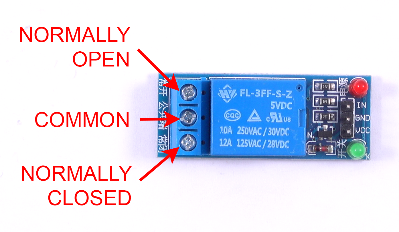
If you're using the same Relay Module as I am, you will likely notice that the terminal markings are in Chinese. The translation for them is as follows:
- Top Terminal - Normally Open
- Middle Terminal - Common
- Bottom Terminal - Normally Closed
If you're using a different Relay or Module, don't forget to check the markings on the device or it's datasheet to ensure you are connecting to the correct terminals/contacts.
Click to open full-size image
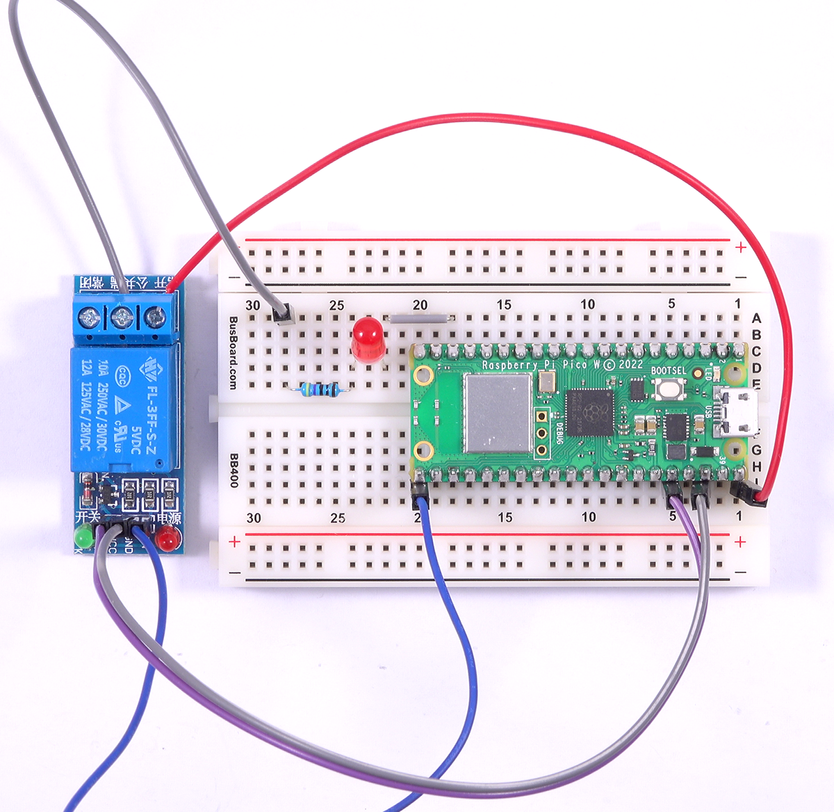
Let's wire up the LED to the control circuit of the Relay.
- Add the LED to the breadboard, connecting its Negative Leg to one of the Ground Pins of the Pico.
- Connect one side of the Resistor to the Positive Leg of the LED
- Connect the other side of the Resistor to the Common terminal of the Relay
- Connect the Normally Open terminal of the Relay to the VBUS pin of the Pico.
We have now completed the Control Circuit!
Note: the VBUS pin on the Pico is connected directly to the Pico's USB 5V power - be careful not to short any wires or you may damage your computer when you plug the USB cable into the Pico!
Click to open full-size image
Example 1: Switching an LED
Now that we have wired up the input and control circuits we are ready to use the Relay to control the LED!
Plug the Pico into your computer, open up Thonny and copy-paste the following code into a new script:
from machine import Pin
import time

relay = Pin(16, Pin.OUT) # The pin that is connected to the Input Circuit of the Relay

while True:  # Loop forever
    relay.value(0)  # Turn the relay ON
    time.sleep(1)
    relay.value(1)  # Turn the relay OFF
    time.sleep(1)
Note: If you used a different GPIO Pin on the Pico - like in the Standalone Relay wiring example above, don't forget to update the script accordingly by changing the number 16 to the GPIO number you are using.
Save the script to the Pico and Run it - all going well you should see the LED toggle between ON and OFF every second!
You should also be able to hear the Relay clicking every second - this is the sound of the electromagnet in the Input Circuit activating the switch of the Control Circuit!
What is the code doing?
The code required to control a relay is very simple, here's what the code is doing:
First we import 'Pin' and 'time', and use 'Pin' to define the GPIO OUTPUT we want to use for controlling the Relay. We will use 'time' later to add pause between toggling the Relay on and off.
from machine import Pin
import time

relay = Pin(16, Pin.OUT) # The pin that is connected to the Input Circuit of the Relay
Next we start an infinite loop with 'While True'
while True: # Loop forever
Finally we control the actual Relay. We turn it on with 'relay.value(0)' and 'time.sleep' for 1 second. Then we do the opposite of turning it back off with 'relay.value(1)' and sleep for another 1 second.
    relay.value(0)  # Turn the relay ON
    time.sleep(1)
    relay.value(1)  # Turn the relay OFF
    time.sleep(1)
Example 2: Switching a Higher Voltage (12V Fan)
We controlled an LED in the previous example, but we could have easily done that without using a Relay.
Let's try something we do need a relay for: Switching a higher voltage circuit from the lower-powered Pico!
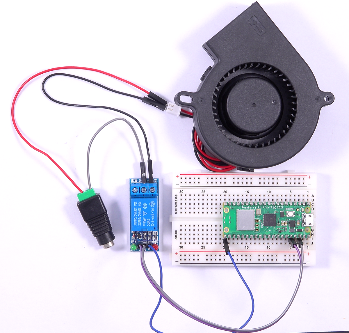
Remove the LED and Resistor from the previous example, and wire up the 12V Fan and Power Supply to the Relay so that it is switching the Negative side of the circuit.
- Connect 12V Negative to the Common terminal of the Relay
- Connect the Normally Open terminal to the Negative wire of the 12V Fan
- Connect the Positive wire of the Fan to 12V Positive
We have now completed the Control Circuit, which is completely isolated from the 3.3V Pico!
Click to open full-size image
Since this is purely a hardware change, we're going to reuse the code from Example 1.
With the 12V circuit all wired up, run the script for Example 1 again on your Pico. All going well, the 12V fan should toggle between ON and OFF every second, along with that now-familiar click of the Relay. You are now switching a higher-powered device/circuit without frying your microcontroller!
Example 3: Normally Open vs Normally Closed
Finally, let's take a closer look at the difference between Normally Open and Normally Closed.
Normally Open
The circuit from the previous example has the 12V Fan connected to the Normally Open terminal of the Relay, which means by default the Fan will be OFF.
Leave it connected that way for now, so we can see Normally Open in practice and the benefits we might use it for.
Create a new file in Thonny and copy-paste the following script:
from machine import Pin
relay = Pin(16, Pin.OUT) # The pin that is connected to the Input Circuit of the Relay
relay.value(0)  # Turn the relay ON
This is a super simple script - all it does is turn on the Relay so that it stays on. Run the script on the Pico and watch the fan turn on and stay on.
Now let's observe the behaviour of Normally Open: Unplug the USB cable of the Pico (and do not touch the 12V power to the fan). The loss of power to the microcontroller has deactivated the Relay and reverted the Control Circuit to the Normally Open position, causing the Fan to turn off.
This is a great feature to have in a system that needs to be turned off when there is a fault, such as a valve in a high-pressure water system - if there were a fault we would likely want to turn the water off automatically to prevent flooding while we found and fixed the fault.
Normally Closed
Now let's see Normally Closed. Leave the Pico disconnected, disconnect the 12V power source, and move the wire connected to the Normally Open terminal of the Relay to the Normally Closed terminal.
Now reconnect the 12V power source - you will see the fan immediately turn on, even with the Pico completely powered off and not running! Normally Closed is ON by default.
Reconnect the USB Cable to your Pico, and run the script again - you should see the fan turn OFF as the Relay activates and moves the Control Circuit across to the Normally Open terminal (which now has nothing connected). Pull the USB cable out from the Pico again, and the Fan turns back on!
At first, this might seem a little pointless - what is the use of a switch that does the opposite of what you want? Well imagine for a second, that instead of a Fan we connected an Emergency Siren, and we added that to the hypothetical high-pressure water system mentioned above. Now when there is a fault in the system not only does the high-pressure valve turn off automatically, but the Emergency Siren also turns on automatically - two useful tasks performed automatically, at the same time, thanks to the handy Relay!
Conclusion
Relays are useful devices that can do a lot more than you might first think!
If your next project needs to control something that runs on a higher power, or you like the idea of having hardware-level fail safes, then look no further than the Relay. We're looking forward to hearing what you come up with in the forums, and if you have any questions or need some help, start the conversation below. We're full-time makers and happy to help.
Happy making!

