If your 3D printer is an Ultimaker S5 then your prints will almost always come out looking brilliant. Although achieving desirable 3D printed components can sometimes require troubleshooting to resolve print errors. These errors often can be solved inside the 3D printing slicing software. This guide is mainly focused on improving results using your CAD (computer-aided design) slicing software but it will briefly talk about beneficial real-world changes when applicable. Sometimes hardware modifications or material selection can yield the greatest improvements.

Often a recipe can be tweaked on evaluation, drizzling in an extra twist of flavour or even a sprinkle of spice. This guide will help provide your prints with the best chance of becoming the greatest they possibly can. Quick links for the contents of this guide are seen below.
- Print Stronger Components
- Fix Surface Blemishes, Stringing and Z Seam
- Improve Build Platform Adhesion and Stop Warping
- Stop Delamination Between Layers
- Prevent Ghosting and Brittle Components
- Improve Surfaces Around Supports
- Small 3D Print Fixes
There is an Ultimaker Cura Overview Guide which is a great reference point if this is your first time encountering Cura and you want to hit the ground running. It is completely free software available online with a great track record, used by over a million users worldwide, and handles around 1.4 million prints per week. Cura can also help expand your creativity and this is best demonstrated in the rundown of Exciting Features in Cura.
Some of these settings talked about will be hidden settings in Cura. To be able to make them visible in the Print Settings Menu go to |Top Tool Bar > Settings > Configure Setting Visibility| then find the particular setting in the list and click on its Checkbox. This guide will be a great way to quickly figure out both what the problem is and how to fix it. If you like what you see here give our Instagram post on Why Your 3D Prints Aren't Perfect a look too. As always if you have got any questions, queries, or things you'd like to see added please let us know your thoughts!
Print Stronger Components
Your component came out aesthetically nice, but you desired a functional component. It needs to be stronger to best serve its purpose. Without changing materials there are several different Ultimaker Cura settings that will strengthen the final 3D printed model. These are explored and evaluated below.
- Infill Density. This setting is a percentage value that determines how much material is built inside your model. 0% produces a hollow object while 100% produces a completely solid object. Most 3D printed parts inside their perimeter walls are of a varying degree of hollowness. A normal fill amount is 20%. This means there will be an infill pattern internally inside your model (like geometric scaffolding) and 80% of anything inside will be empty space. The more you increase this percentage value the stronger your model will become. 50% and above are great values for functional 3D prints. Infill density can be accessed in the Recommended Print Settings as a slider or under the Infill Heading in the Custom Print Settings as a percentage value.
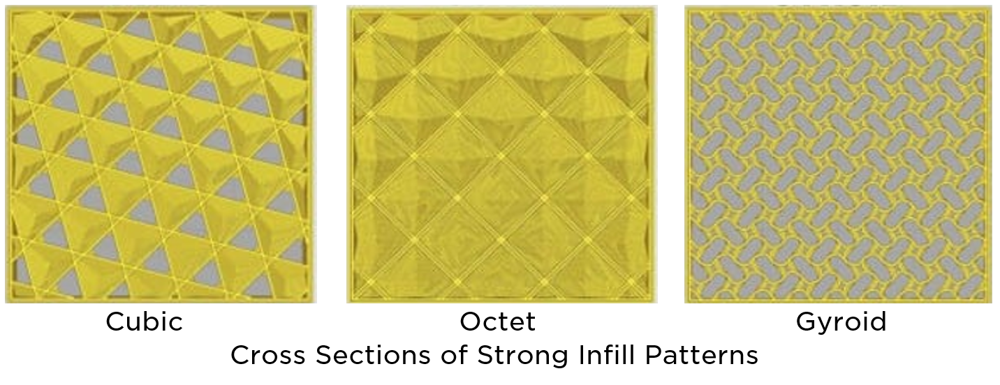
- Infill Pattern. There are several different types of infill patterns which are grid-like structures printed inside your model. Imagine these as geometric scaffolding. These can be used to increase strength, increase speed or improve flexibility in 3D printed components. Examples of strong Infill Patterns are Cubic, Octet, and Gyroid. Cubic is a 3D pattern of stacked and tilted cubes. Octet is a pattern that stacks pyramidical shapes. Gyroid infill is a pattern that looks like a wave and offers great strength when the model is stressed in multiple directions. Using any of these Infill Patterns will increase the strength of your model as compared to the default Triangles pattern. Infill Pattern setting can be found under the Infill Heading in Custom Print Settings.
- Wall Thickness and Top/Bottom Thickness. By increasing the values of these settings your printer will run more perimeter walls along around the surface of your model. This is a simple change that will yield an excellent improvement to strength results. It is also very economical as it uses only a little extra material for significantly greater rigidity. Worth noting the final model will not be larger as the perimeter lines will be laid internally inside the 3D print. The number of perimeter lines laid is a function of these settings and Line Width. Bumping up the values to have four perimeter lines is a great starting point. These hidden settings are found in Ultimaker Cura in the Custom Print Settings under the Shell Heading.
- Flow. Flow adjusts the amount of material being pumped out of the extruder nozzle which in Cura is determined by a percentage value. Over-extruding is a method to increase strength. Over-extruding means increasing the Flow value above 100%. This will cause a greater amount of material to be deposited as the model is printed. More material creates thicker walls and more mass which in turn creates a stronger component. Using a 140% value for Flow will produce models aesthetically comparable to models that use 100% value for Flow. A 150% value for Flow will give the strongest component using this technique. Flow values greater than 150% will end up structurally weaker and show blemishes on the surface of the component. This setting is found under the Material Heading in the Custom Print Settings.
Fix Surface Blemishes, Stringing and Z Seam
It can be difficult to join two pieces of plastic together without leaving marks but Ultimaker Cura offers several options to make this possible. On 3D prints, blemishes look like blobs, and stringing looks like whiskers or hairs. Both can be distributed all over the component. On close inspection, one can see that each individual error belongs to one layer. This is because the filament is incorrectly under pressure causing it to ooze incorrectly out of the print nozzle. These will be at locations where retraction or coasting occurs. Retraction is when the feeder pulls the filament away from the nozzle. Coasting is when the feeder stops all movement. Z-Seam is a specific name for a blemish that travels vertically up a printed object. Its location is determined by the point where a new layer is started. This happens because of a short burst of over extrusion that occurs when the print head finishes a layer.
Without using Ultimaker Cura these blemishes could be sanded smooth as a post-processing method. Other external to Cura methods is to keep the nozzle clean and to store hygroscopic filament properly.
There are many different methods within Cura to stop blemishes, stringing, and Z Seam. Some of the different Ultimaker Cura settings worth altering to prevent these on your 3D printed components are discussed below.
- Print Speed and Printing Temperature. Print Speed determines the overall speed of your 3D printer. A simple method of slowing printing to 20-30mm/s can help minimise blemishes and stringing. Print Speed is found under the Speed Heading in Custom Print Settings. By lowering the Print Head Temperature at 5° intervals it will give the best opportunity for the material to be deposited effectively. This will stop it from being too viscous which causes blemishes and stringing. This setting is found under the Material Heading in Custom Print Settings.
- Outer Wall Speed. In Cura as well as several other 3D printing slicing software by default they print the outside walls at a slower speed than infill pattern or internal perimeter walls. This speed change variation can be the cause of blemishes as the material is deposited on the surface due to over-extruding filament. By setting this value the same as your Print Speed you will prevent this. This setting is found under the Speed Heading in the Custom Print Settings.
- Z Seam Alignment. This option allows the starting location of each layer to be determined or made random for each layer. Z Seam blemishes can be hidden very well using the Sharpest Corner selection if your model has a sharp corner running up along the Z-Axis. Worth noting is this setting will not remove the blemishes but presents ways to disguise them. For instance, if the model was only ever going to be viewed from the front you could adjust the Z Seam to be on the back of the object. This setting is found under the Shell Heading in the Custom Print Settings.
- Alter the Coasting Setting. Closely watch the model printing. If the blemish occurs at the end of the layer when the extruder is coming to a stop, Coasting settings should be adjusted. Coasting slows extrusion a short distance before the perimeter end by stopping the feeder. This allows the pressure in the print nozzle to be relieved. The setting to alter in Cura is Minimum Volume Before Coasting. Modifying this by 0.2mm³ increments will be enough to show noticeable impacts. This hidden setting will be found under the Experimental Heading in Custom Print Settings.
- Alter the Retraction Settings. Closely watch the model printing. If the blemish occurs at the start of a new layer, Retraction is the setting to adjust. Retraction pulls the filament backwards out of the hot nozzle which relieves pressure and stops extrusion. To find the Retraction sweet point the two settings in Cura are Retraction Speed and Retraction Distance. Retraction Speed determines how quickly the filament is pulled back. This will be slow if blemishes are occurring, tweak by increasing in 5mm/s increments. Retraction Distance is how far the filament will be pulled backwards. If too low it will not relieve enough pressure, tweak by increasing 1mm at a time. These settings are found under the Travel Heading in Custom Print Settings.
Improve Build Platform Adhesion and Stop Warping

External to Cura, often the main problem with build platform adhesion has to do with the build platform. Usually, this problem is that the build platform isn’t perfectly parallel with the plane of the nozzle path (X-Y Plane). To calibrate Ultimaker 3D Printers here is an Ultimaker 3D Printer Build Platform Calibration guide. Another problem is certain materials, such as ABS, struggle to grip to build platforms. So changing to a better material can yield much-improved adhesion. Information about materials can be found in the 3D Printing Material Guide. There are also numerous glues and platform stickers/covers that can be used to improve build platform adhesion and stop warping.
There are many different methods within Cura to stop improve build platform adhesion. Some of the different Ultimaker Cura settings worth altering to improve adhesion on your 3D printed components are discussed below.
- Enable Prime Blob. A simple method to make sure your nozzle is ready to start laying material from the get-go is using a prime blob. When used 3D prints will start with the nozzle producing a glob of extruded filament in the corner of the build platform. This ensures the extruder will have material ready at the nozzle before the commencement of component printing. This setting is found under the Build Plate Adhesion Heading in Custom Print Settings.
- Bed Temperature. Depending on the type of material used different bed temperatures are required to ensure the best possible adhesion result. It is important to get these just right. For example, ABS a bed temperature of around 120°C is needed whereas for PLA a bed temperature of around 60°C is recommended. Also retaining build platform heating to a higher layer height will improve build platform adhesion. These settings can be found under the Material Heading in Custom Print Settings.
- Lower Fan Cooling. By minimising the cooling of the earlier layers you will be able to get the best adhesion between the platform and the first printed layers. Cooling makes the filament material contract which creates warping stresses. If these overcome the adhesion strength the material will pull away from the build platform. Adhesion can be improved using these settings; Regular Fan Speed At Layer and Initial Fan Speed. Increase the value of Regular Fan Speed At Layer to a higher layer level. This will create less cooling on earlier layers and improve build platform adhesion. Regular Fan Speed setting is a percentage value that directly determines the amount of airflow that the fan produces. Minimise this to improve build platform adhesion. These settings will be found under the Cooling Heading in Custom Print Settings.
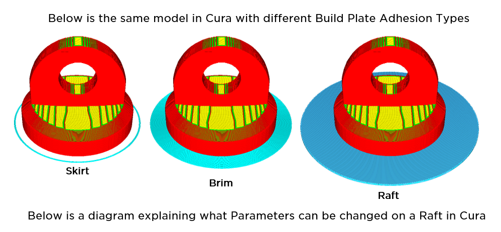
- Bed Adhesion Type. These are different methods to both prime your nozzle ready for extrusion and to improve adhesion to the build platform. The Skirt feature is a line printed around the model and is not connected to the model. Brim feature adds a single layer flat area around the base of your model to prevent warping. Brim feature has several intuitive settings associated with it. Raft feature adds a thick grid with a roof below the model. Raft feature has an extensive amount of settings associated with it. Below there is a diagram that is a great reference in association with these settings. Bed Adhesion Type settings are found under the Build Plate Adhesion Heading in Custom Print Settings.
Stop Delamination Between Layers

External from Cura methods to decrease the chance of delamination involves closing doors or encasing the 3D printer. The aim is to keep the temperature changes and airflows away from the 3D printer. Windows, fans, air-conditioners can all drastically affect 3D prints.
There are many different methods within Cura to minimise and stop delamination. The best Ultimaker Cura settings worth altering to prevent this are discussed below.
- Flow and Nozzle Temperature. Making sure Flow and Nozzle Temperature are correctly set for your model is crucial. Both these settings directly impact the flow rate of filament through the nozzle. By laying down more material it will improve the chances that the layer-on-layer adhesion strength will be greater than the warping forces. To tweak these increase Flow value by 5% increments and increase Nozzle Temperature value by 5°C increments. These Settings can be found under the Material Heading in Custom Print Settings.
- Enable Draft Shield. This will create a wall structure around the model as it is printed. This will trap hot air and shields it against exterior airflows. Particularly useful for materials that warp easily. This hidden setting can be found under the Experimental Heading in Custom Print Settings.
Prevent Ghosting and Brittle Components
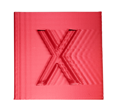
Externally from Cura to address these problems it is very important to find a solid base for your 3D Printer to sit on. Consider using vibration dampening printer feet or a non-slip mat. Also, take the time to adjust the 3D printer tensioner to remove slack from the 3D printer belts. If correctly tensioned your belts should be tight and make a low-sounding note if plucked.
However, these issues can be solved inside Ultimaker Cura. Some of the different Ultimaker Cura settings worth altering relieve some of these issues are as follows.
- Print Speed. By slowing the print head there will be fewer quick movements and thus smaller print head inertia. Smaller inertia means fewer vibrations through the 3D printing system. This will directly lower the effect of ghosting as the print head will not jerk around as aggressively. An excellent slower print speed would 20-30mm/s. Print Speed is found under the Speed Heading in Custom Print Settings.
- Mesh Fixes. Editing the print mesh can allow for simplified G-Code. G-code is the recipe that Cura produces and what the 3D printer follows. By simplifying the path for the print nozzle there will be fewer inertial changes for the extruder head. This setting will help minimise Ghosting but it will cause a small loss in resolution of the final model. The three settings worth changing are as follows. Maximum Resolution determines the minimum size of the line segment after slicing. Maximum Travel Resolution determines the minimum size of a travel line segment after slicing. Maximum Deviation is the maximum deviation allowed when reducing the resolution. The infographic below demonstrates how these settings evaluate the nozzle path and determine if a section can be simplified or not. The top section will have the red line turned into the new nozzle path as the deviation is small. The bottom section will retain the original nozzle path because the deviation on the bottom is too large. These are hidden settings found under the Mesh Fixes Heading in Custom Print Settings.
Improve Surfaces Around Supports
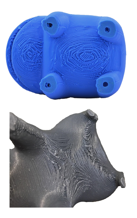
External from Cura you can use dual-extrusion in combination with water-soluble supports such as Ultimaker PVA. This will let you create very dense supports that can be easily removed. Check out Dual-Extrusion Printing Guide for more information on how best to employ dual-extrusion on future 3D prints. You can also change to a nozzle with a smaller diameter and print using smaller layer heights. This will take more time to print but definitely improves the surface.
There are many different methods within Cura to help improve the final component surface around where the supports are connected to. These settings are discussed below.
- Support Density. Increasing the density of supports creates more supports. This improves their assistance to the model. It will help stop material droop from edges that requiring support which will improve surface finish. The default in Cura is a Support Density value of 15%. To make surfaces around supports better increase Support Density value to 40% or greater. Support Density is a hidden setting and is found under the Support Heading in the Custom Print Settings.
- Support Overhang Angle. Decreasing the Support Overhang Angle value, default is 60°, will make Cura produce supports on less extreme angles over the component. This is good for when the poor surfaces start even before the location of the supports. An example of this would be a lengthy bridge of material. This would run into problems as the print would be prone to sagging. This setting is found under the Support Heading in Custom Print Settings.
- Support Z Distance and Support X/Y Distance. These two settings determine exactly how close the support structure is built next to the final model. The closer it is built the greater the support but the harder it will be to remove. There is a fine line between too close where you will cause artifacts on the surface of the model and not close enough where you will end up with saggy, messy-looking edges. Support Z Distance will help keep the top of your supports from bonding to the bottom of your part, commonly between 0.6-0.2. Support X/Y Distance will keep the sides of your supports from bonding to the side of your model, commonly between 0.2-1mm. These values can be significantly smaller if dual-extrusion is employed allowing specifically support material to be employed. These hidden settings are found under the Support Heading in Custom Print Settings.
- Tree Supports. This support is an experimental feature in Cura which is particularly effective at supporting organic shapes. Models of humans or animals will print better with these supports. Much like the name implies instead of producing supports in straight lines these supports use an automatically generated tree-esque structure which is used to support models. Both on material and print time will be saved by 3D printing with these supports. They will also produce a better bottom surface. Tree Supports are very effective and they are further explored in the Exciting Features in Cura Guide. This hidden setting is found under the Support Heading in Custom Print Settings.
Small 3D Print Fixes
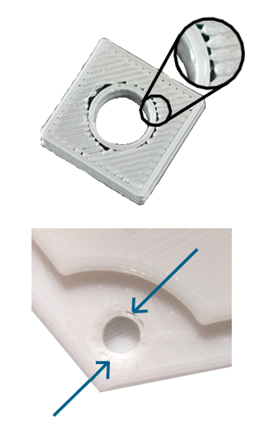
Externally from Cura to solve this it would be possible to use a nozzle with a smaller diameter which would allow smaller line widths to be laid and take more time, fixing these issues.
However, these issues with small 3D prints can be solved inside Ultimaker Cura. Some of the different Ultimaker Cura settings worth altering relieve some of these issues are as follows.
- Fill Gaps Between Walls. This setting lets you choose how Cura handles gaps between the inside and outside walls. By selecting Everywhere the gaps between walls will be filled with material even where no walls can fit. This is a hidden setting which is found under the Shell Heading in Custom Print Settings.
- Minimum Layer Time. This will set a minimum time to complete each layer. Setting it higher it will allow more time for the deposited material to cool down through convection. If your small prints are distorted start by using a 10 second minimum layer time. Increase this value by 5-second increments to find the best value. Minimum Layer Time setting is found under the Cooling Heading in Custom Print Settings.
- Higher Fan Cooling. By maximising the cooling of the earlier layers you’ll be able to get the best possible inter-layer adhesion. Start by setting Fan Speed setting at 100%. Then adjust Regular Fan Speed at Layer so that it starts at the second layer. This will give you significantly increased cooling for the second layer whilst still allowing the first layer to adhere correctly to the bed. These settings are found under the Cooling Heading in Custom Print Settings.
Follow what I say and you will be printing models without support that look insane. Just like the one below.

