
Dual VNH3SP30 Motor Driver Carrier MD03A
Retired Product
Replaced by: POLOLU-2507This product is no longer available. This page is only for reference.
 |
The Pololu dual high-power motor drivers are compact carriers for the VNH3SP30 and VNH2SP30 motor driver integrated circuits from ST. The board incorporates most of the components of the typical application diagram on page 8 of the VNH2SP30 datasheet, including pull-up and current-limiting resistors and a FET for reverse battery protection. (The current sense circuit might not be populated on the VNH3SP30 version of the board since only the VNH2SP30 supports current sense.) To keep the number of I/O lines down, the two enable/diagnostic lines on each chip are tied together. All you need to add is a microcontroller or other control circuit to turn the H-Bridges on and off.
Please note that Pololu offer several other products based on these same chips, including single carrier boards for controlling one motor, the qik 2s12v10 dual serial motor controller, the TReX motor controller, the jrk 12v12 USB motor controller with feedback, and the Orangutan X2 robot controller. Pololu also have a family of higher-power motor drivers that can deliver more current over a wider operating voltage range.
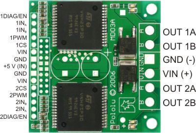 |
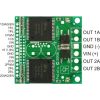
In a typical application, the power connections are made on one end of the board, and the control connections are made on the other end. +5 volts must be supplied to the board through the smaller 0.1"-spaced pins; the input voltage is available at those pins as well, but the connection is not intended for currents exceeding a few amps. The diagnostic pins can be left disconnected if you do not want to monitor the fault conditions of the motor drivers. INA and INB control the direction of each motor, and the PWM pins turns the motors on or off. For the VNH2SP30 version, the current sense (CS) pins will output approximately 0.13 volts per amp of output current. If you want to add current sensing to the VNH3SP30 version, or if you want higher-accuracy current sensing with the VNH2SP30 version, please consider Pololu's ±30A ACS714 current sensor carrier.
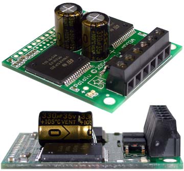 |
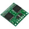
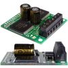
The dual motor driver PCB includes provisions for installing up to three large capacitors to limit disturbances on the main power line. Two 10mm radial capacitors may be mounted between the motor driver ICs, and an axial capacitor may be mounted between the ICs and power connections. It is generally not necessary to use all three capacitors; two radial capacitors are included with each unit. For applications that require a low profile, a single capacitor can be installed on its side as shown in the picture to the right.
Note: A 0.1" breakaway male header strip, three 2-pin terminal blocks, and two electrolytic capacitors are included but not soldered onto the boards. No printed documentation is shipped with these items; please see the VNH3SP30 and VNH2SP30 datasheets linked under the Resources tab.
VNH3SP30 and VNH2SP30 Comparison
| VNH3SP30 | VNH2SP30 | |
|---|---|---|
| Operating supply voltage (Vcc) | 5.5 – 36 V* | 5.5 – 16 V |
| Maximum current rating | 30 A | 30 A |
| MOSFET on-resistance (per leg) | 34 mO | 19 mO |
| Maximum PWM frequency | 10 kHz | 20 kHz |
| Current sense | none | approximately 0.13 V/A |
| Over-voltage shutoff | 36 V* | 16 V minimum (19 V typical) |
| Time to overheat at 20 A** | 8 seconds | 35 seconds |
| Time to overheat at 15 A** | 30 seconds | 150 seconds |
| Current for infinite run time** | 9 A | 14 A |
*Manufacturer specification. In Pololu's experience, shoot-through currents make PWM operation impractical above 16 V.
**Typical results using Pololu motor driver carrier with 100% duty cycle at room temperature.
Real-world power dissipation considerations
The motor drivers have maximum current ratings of 30 A continuous. However, the chips by themselves will overheat at lower currents (see table above for typical values). The actual current you can deliver will depend on how well you can keep the motor drivers cool. The carrier printed circuit board is designed to draw heat out of the motor driver chips, but performance can be improved by adding a heat sink. In Pololu's tests, Pololu were able to deliver short durations (on the order of milliseconds) of 30 A and several seconds of 20 A without overheating. At 6 A, the chip gets just barely noticeably warm to the touch. For high-current installations, the motor and power supply wires should also be soldered directly instead of going through the supplied terminal blocks, which are rated for up to 15 A.
This product can get hot enough to burn you long before the chip overheats. Take care when handling this product and other components connected to it.
Many motor controllers or speed controllers can have peak current ratings that are substantially higher than the continuous current rating; this is not the case with these motor drivers, which have a 30 A continuous rating and over-current protection that can kick in as low as 30 A (45 A typical). Therefore, the stall current of your motor should not be more than 30 A. (Even if you expect to run at a much lower average current, the motor can still draw high currents when it is starting or if you use low duty cycle PWM to keep the average current down.)
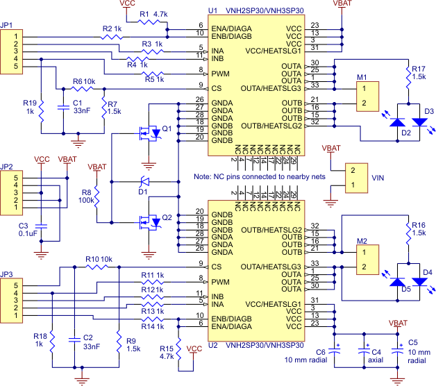 |
Schematic of the Pololu Dual High Current Motor Driver Carrier |
|---|
People often buy this product together with:
 | Dual VNH2SP30 Motor Driver Carrier MD03A |
 | Pololu Universal Aluminum Mounting Hub for 6mm Shaft, #4-40 Holes (2-Pack) |
 | Pololu Stamped Aluminum L-Bracket Pair for 37D mm Metal Gearmotors |
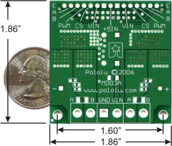
Dimensions
| Size: | 1.86" × 1.86" |
|---|
General specifications
| Motor driver: | VNH3SP30 |
|---|---|
| Motor channels: | 2 |
| Minimum operating voltage: | 5.5 V |
| Maximum operating voltage: | 16 V1 |
| Continuous output current per channel: | 9 A |
| Peak output current per channel: | 30 A |
| Continuous paralleled output current: | 15 A |
| Maximum PWM frequency: | 10 kHz |
| Reverse voltage protection?: | Y2 |
Notes:
- 1
- The datasheet claims a maximum of 36 V, but shoot-through issues make operation impractical above 16 V.
- 2
- There are unprotected electrolytic capacitors that will be damaged by reverse voltage.
File downloads
-
VNH3SP30 motor driver datasheet (586k pdf)
-
VNH2SP30 motor driver datasheet (670k pdf)
-
IRFR3707Z MOSFET datasheet (223k pdf)
-
STD60NF3LL MOSFET datasheet (413k pdf)
-
Dual Motor Driver Carrier VNH2SP30 or VNH3SP30 drill guide (122k dxf)
This DXF drawing shows the locations of all of the board’s holes.
Exact shipping can be calculated on the view cart page (no login required).
Products that weigh more than 0.5 KG may cost more than what's shown (for example, test equipment, machines, >500mL liquids, etc).
We deliver Australia-wide with these options (depends on the final destination - you can get a quote on the view cart page):
- $3+ for Stamped Mail (typically 10+ business days, not tracked, only available on selected small items)
- $7+ for Standard Post (typically 6+ business days, tracked)
- $11+ for Express Post (typically 2+ business days, tracked)
- Pickup - Free! Only available to customers who live in the Newcastle region (must order online and only pickup after we email to notify you the order is ready). Orders placed after 2PM may not be ready until the following business day.
Non-metro addresses in WA, NT, SA & TAS can take 2+ days in addition to the above information.
Some batteries (such as LiPo) can't be shipped by Air. During checkout, Express Post and International Methods will not be an option if you have that type of battery in your shopping cart.
International Orders - the following rates are for New Zealand and will vary for other countries:
- $12+ for Pack and Track (3+ days, tracked)
- $16+ for Express International (2-5 days, tracked)
If you order lots of gear, the postage amount will increase based on the weight of your order.
Our physical address (here's a PDF which includes other key business details):
40 Aruma Place
Cardiff
NSW, 2285
Australia
Take a look at our customer service page if you have other questions such as "do we do purchase orders" (yes!) or "are prices GST inclusive" (yes they are!). We're here to help - get in touch with us to talk shop.
Have a product question? We're here to help!
Guides

The Maker Revolution
Projects

The Rats Nest VCC Desktop Power Supply

Remote-Controlled Mars Rover

FlipperMate: Hands-Free Pinball

Makers love reviews as much as you do, please follow this link to review the products you have purchased.
Product Comments