
ACS711EX Current Sensor Carrier -15.5A to +15.5A
Available with a lead time
Expect dispatch between Mar 10 and Mar 13
Quantity Discounts:
- 10+ $7.15 (exc GST)
- 25+ $6.94 (exc GST)
 |
 |
This current sensor is a carrier board or breakout board for Allegro’s ACS711KEXLT-15AB-T Hall effect-based linear current sensor with overcurrent fault output; Pololu therefore recommend careful reading of the ACS711 datasheet (533k pdf) before using this product. This sensor has an operating voltage of 3 V to 5.5 V and an output sensitivity of 90 mV/A when Vcc is 3.3 V (or 136 mV/A when Vcc is 5 V). The following list details some of the sensor’s key features:
- Designed for bidirectional input current from -15.5 A to 15.5 A (though the robust sensor IC can tolerate 100 ms transient current spikes up to 100 A).
- Conductive path internal resistance is typically 0.6 mO, and the PCB is made with 2-oz copper, so very little power is lost in the board.
- Use of a Hall effect sensor means the IC is able to electrically isolate the current path from the sensor’s electronics (for applications up to 100 V), which allows the sensor to be inserted anywhere along the current path and to be used in applications that require electrical isolation.
- 100 kHz bandwidth.
- Good accuracy and reliability: factory calibration results in a typical total output error of ±5% at room temperature, the output offset voltage is extremely stable, and the sensor has zero magnetic hysteresis.
- Overcurrent FAULT output latches low when current magnitude exceeds 15.5 A.
- Operating temperature range of -40°C to 125°C.
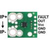
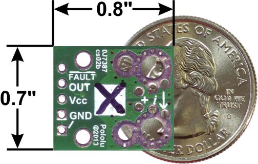
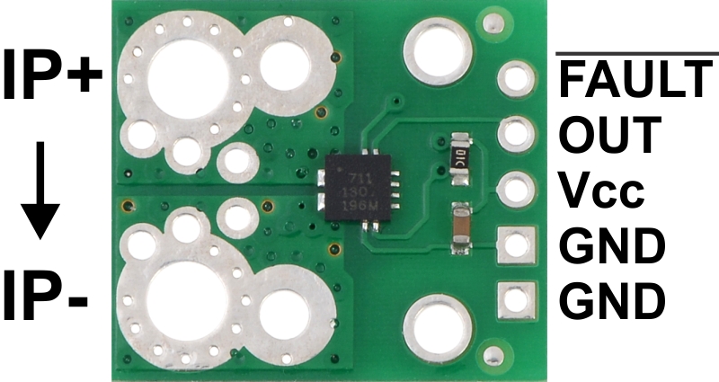
The pads are labeled on the bottom silkscreen, as shown in the picture to the right. The silkscreen also shows the direction that is interpreted as positive current flow via the +i arrow.
This 15.5 A current sensor is marked with a black X. Pololu also sell a 31 A version that uses the same carrier PCB; you can distinguish the versions by reading the text on the IC or by looking at the color of the X on the bottom silkscreen.
This sensor is very similar to Pololu's original ACS711 -12.5 to +12.5 A Current Sensor Carrier, but uses a smaller “EX” package that has a larger optimized sensing range and reduced internal resistance. The board size, pinout, and hole locations are all unchanged, so it can generally be used as a drop-in replacement for Pololu's ACS711 carriers with “LC” packages.
Using the sensor
Electrical connections
The sensor requires a supply voltage of 3 V to 5.5 V to be connected across the Vcc and GND pads, which are labeled on the bottom silkscreen. The sensor outputs an analog voltage that is linearly proportional to the input current. The quiescent output voltage is Vcc/2 and changes by 90 mV per amp of input current (when Vcc = 3.3 V), with positive current increasing the output voltage and negative current decreasing the output voltage. The relationship between the instantaneous input current, i, and sensor output voltage, VOUT, can be represented by the following equations:
 |
The FAULT pin is normally high and latches low when the current exceeds ±15.5 A. Once the FAULT pin is latched low, the only way to reset it is by toggling power on the Vcc pin. In Pololu's tests, this module was able to handle 15 A of continuous current without exceeding 50°C, with no cooling beyond the heat dissipation of the PCB.
|
|
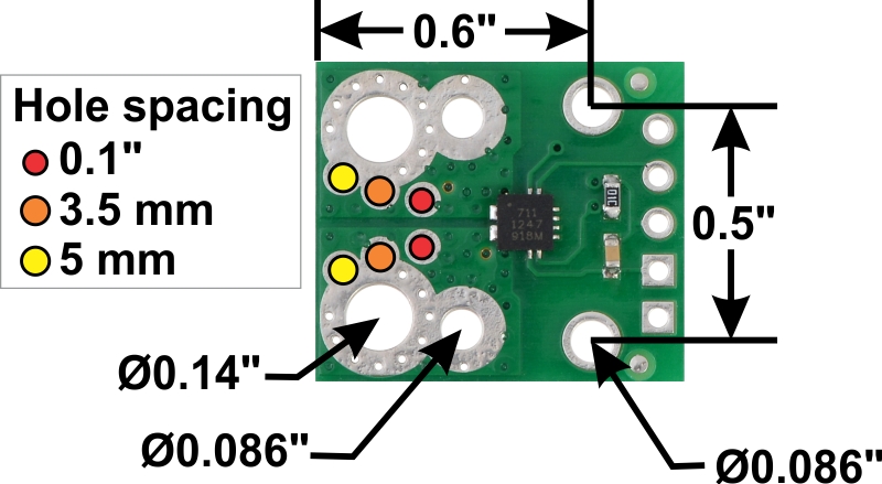
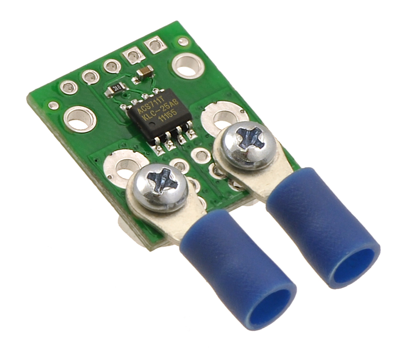
The input current can be connected to the board in a variety of ways. Holes with 0.1", 3.5 mm, and 5 mm spacing are available as shown in the diagram above for connecting male header pins or terminal blocks. For high-current applications, you can solder wires directly to the through-holes that best match your wires, or you can use solderless ring terminal connectors, as shown in the picture above. The large through-holes are big enough for #6 screws.
Warning: This product is intended for use below 30 V. Working with higher voltages can be extremely dangerous and should only be attempted by qualified individuals with appropriate equipment and protective gear.
Mounting information
The board has two mounting holes on the logic side of the board. These mounting holes are 0.5" apart and are designed for #2 screws.
Included components
This board ships assembled with all surface mount components, and a 5×1 strip of 0.1" header pins is included but not soldered in, as shown in the picture below.
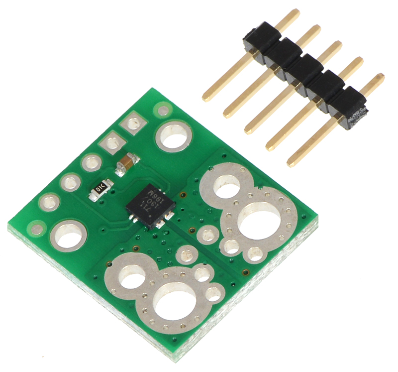 |
ACS711EX current sensor carrier with included 5 × 1 0.1" header pins. |
|---|
Schematic diagram
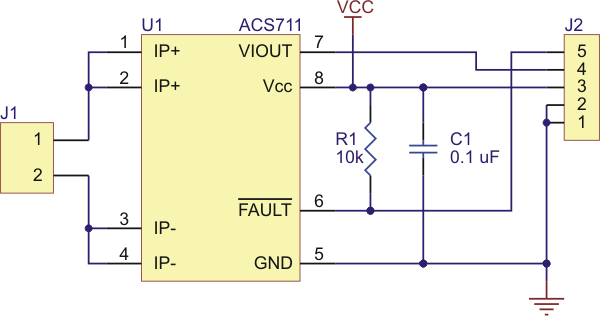 |
ACS711 current sensor carrier schematic diagram. |
|---|
People often buy this product together with:
 | ACS714 Current Sensor Carrier -5A to +5A |
 | ACS711EX Current Sensor Carrier -31A to +31A |
Dimensions
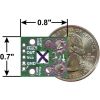
| Size: | 0.7" x 0.8" |
|---|---|
| Weight: | 1.0 g1 |
General specifications
| Current sense: | 0.090 V/A2 |
|---|---|
| Minimum logic voltage: | 3 V |
| Maximum logic voltage: | 5.5 V |
| Supply current: | 4 mA |
Identifying markings
| PCB dev codes: | cs02b |
|---|---|
| Other PCB markings: | 0J7387, white box with black X |
Notes:
- 1
- Without included optional header pins.
- 2
- When Vcc is 3.3 V. This specification is proportional to Vcc.
File downloads
-
Allegro ACS711 current sensor datasheet (533k pdf)
-
Drill guide for ACS711EX Current Sensor Carrier (43k dxf)
This DXF drawing shows the locations of all of the board’s holes.
Exact shipping can be calculated on the view cart page (no login required).
Products that weigh more than 0.5 KG may cost more than what's shown (for example, test equipment, machines, >500mL liquids, etc).
We deliver Australia-wide with these options (depends on the final destination - you can get a quote on the view cart page):
- $3+ for Stamped Mail (typically 10+ business days, not tracked, only available on selected small items)
- $7+ for Standard Post (typically 6+ business days, tracked)
- $11+ for Express Post (typically 2+ business days, tracked)
- Pickup - Free! Only available to customers who live in the Newcastle region (must order online and only pickup after we email to notify you the order is ready). Orders placed after 2PM may not be ready until the following business day.
Non-metro addresses in WA, NT, SA & TAS can take 2+ days in addition to the above information.
Some batteries (such as LiPo) can't be shipped by Air. During checkout, Express Post and International Methods will not be an option if you have that type of battery in your shopping cart.
International Orders - the following rates are for New Zealand and will vary for other countries:
- $12+ for Pack and Track (3+ days, tracked)
- $16+ for Express International (2-5 days, tracked)
If you order lots of gear, the postage amount will increase based on the weight of your order.
Our physical address (here's a PDF which includes other key business details):
40 Aruma Place
Cardiff
NSW, 2285
Australia
Take a look at our customer service page if you have other questions such as "do we do purchase orders" (yes!) or "are prices GST inclusive" (yes they are!). We're here to help - get in touch with us to talk shop.
Have a product question? We're here to help!
 Solderless Breadboard - 830 Tie Point (ZY-102)SKU: CE00304 Brand: Core ElectronicsIf you're prototyping a circuit big or small, then you'll want a quality breadbo ...
-
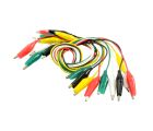
- Alligator Clip Wire / Cable 10 PackSKU: 019-ZY-810 Brand: Core ElectronicsGreat for prototyping and interfacing with devices. 5 colors per pack, 2 of each ...
- DHT22 Temperature and Relative Humidity Sensor ModuleSKU: 018-DHT22 Brand: Core ElectronicsThe DHT22 is a step up from the older DHT11 and has some improved features.

Videos
View AllGuides

The Maker Revolution

Getting Hands-on with Sensors
Projects

WhyzaGC - Feather ESP32 addon to the MightyOhm Gieger Counter

Makers love reviews as much as you do, please follow this link to review the products you have purchased.
Product Comments