 So in case you haven’t heard yet, digital LEDs are the go-to solution for any project that uses RGB LEDs and you want to avoid the rat's nest that ensures when using multiple RGB LEDs, each colour requiring its own connection. Digitally addressable LEDs allow you to control large numbers of LEDs using digital communication to tiny onboard chips integrated into the LEDs which read these digital commands and do all the heavy lifting for you. The go-to LED chip for these purposes has been the WS2812 which you might know most prominently as Adafruit’s NeoPixels. These have been around for a few years, and are fantastic, low-cost devices which bring your rainbow creations to life, however, there are several disadvantages to these chips. They require a very specific 800Khz data transfer rate which uses very exact timing pulses to transfer the data. This isn’t an issue for real-time processors such as Arduino, Particle, Teensy, and other such platforms, however, driving them from operating system based platforms such as Raspberry Pi isn’t recommended because of the timing required by the chips. They may work, but you may not get stable operation. Never fear, however, there’s another chip in town designed to offer a solution for this timing protocol, the APA102(or SK98225), used by Adafruit in their DotStar digital LEDs.
Adafruit provides a fantastic comparison between NeoPixels and DotStar LEDs so we won’t go into that too much, rather we’ll be taking a look at the key features of the DotStar LEDs and how to use them. If you're looking for information specifically on NeoPixel's we've got a separate article for those here.
Why DotStar LEDs?
DotStar LEDs are awesome. They operate over a generic 2-wire SPI bus which removes the need for a finicky transfer speed and allows for data transfer at 8-32Mhz rather than 800Khz. The APA102 chip uses PWM rates of 19.2Khz which allows DotStar LEDs to be used in Persistence of Vision (POV) displays and smoother PWM fading. However instead of only requiring a single pin to transfer data, the DotStar LEDs require two, so let’s take a look at how to use them.
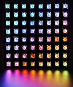
If you're looking for a great way to get started with DotStar LED, then check out this sweet 8x8 flexible DotStar matrix as shown above. It'll be sure to kick your creative mind into gear for your next project.
Using DotStar LEDs
Using DotStar LEDs is incredibly easy, no matter what platform you’re on thanks to Adafruit’s fantastic libraries for both Arduino and Raspberry Pi. If you go to the link we posted above to Adafruit’s site, they provide access to libraries for both the Raspberry Pi and Arduino which both use the same object orientated control, however with the syntax for Python vs. C (Arduino).
If you’ve used NeoPixels before, then you’ll be familiar with the basic functionality of the library. After initializing the DotStar object (you can have multiple objects, or daisy chain them), you set the colour of the LEDs using the .setPixelColor(n,R,G,B) and then use the .show() to display that colour on the targeted pixel. Everything else used to create pretty animations and effects is just manipulation of those two commands, so it’s incredibly easy to implement DotStar LEDs into your projects.
To wire up your DotStar strip or display, it’s important to note that data flows in one direction. Manufacturing processes can change the order of the pins, and even which end a connector is attached to so it’s important that before use you always check on the strip which pins is which. Speaking of pins, there are 4 pins required to use DotStar LEDS:
- Power (5V) DO NOT USE THE 5V OUTPUT OF YOUR BOARD! We’ll explain this further below
- Ground
- Clock
- Data
**Note that as DotStars are 5V devices, whilst 3.3V may be enough to drive it, you should use a logic level converter if you’re using them with a 3.3V board such as Teensy or Raspberry Pi**

The clock and data pins can be connected up to any digital pin on your board, you’ll just need to specify this pin when you initialise the object. As mentioned above, DotStar LEDs operate over an SPI protocol just using the CLOCK and DATA OUT pins from your microcontrollers, but the beauty of the libraries is that you can use any digital pins for software SPI given your microcontroller can run fast enough for software SPI (anything over 8MHz will be fine). Alternatively feel free to use the pins on your microcontroller that connect to the hardware SPI bus of the chip to free up software resources.
For more info on the specifics of using the libraries, check out the Arduino and Raspberry Pi Github pages.
Sample Code
To get your precious DotStar strips up and running and confirm that every LED colour is working the way it's supposed to, Adafruit has provided some fantastic example code. There're some extra layers added to this code if you're using a Gemma or Trinket board which require some special setup, however everything else is pretty straight forward, and code can be used pretty much line for line with DotStar LEDs and NeoPixel LEDs providing you use the correct library.
// Simple strand test for Adafruit Dot Star RGB LED strip.
// This is a basic diagnostic tool, NOT a graphics demo...helps confirm
// correct wiring and tests each pixel's ability to display red, green
// and blue and to forward data down the line.  By limiting the number
// and color of LEDs, it's reasonably safe to power a couple meters off
// the Arduino's 5V pin.  DON'T try that with other code!

#include <Adafruit_DotStar.h>
// Because conditional #includes don't work w/Arduino sketches...
#include          // COMMENT OUT THIS LINE FOR GEMMA OR TRINKET
//#include <avr/power.h> // ENABLE THIS LINE FOR GEMMA OR TRINKET

#define NUMPIXELS 30 // Number of LEDs in strip

// Here's how to control the LEDs from any two pins:
#define DATAPIN    4
#define CLOCKPIN   5
Adafruit_DotStar strip = Adafruit_DotStar(
  NUMPIXELS, DATAPIN, CLOCKPIN, DOTSTAR_BRG);
// The last parameter is optional -- this is the color data order of the
// DotStar strip, which has changed over time in different production runs.
// Your code just uses R,G,B colors, the library then reassigns as needed.
// Default is DOTSTAR_BRG, so change this if you have an earlier strip.

// Hardware SPI is a little faster, but must be wired to specific pins
// (Arduino Uno = pin 11 for data, 13 for clock, other boards are different).
//Adafruit_DotStar strip = Adafruit_DotStar(NUMPIXELS, DOTSTAR_BRG);

void setup() {

#if defined(__AVR_ATtiny85__) && (F_CPU == 16000000L)
  clock_prescale_set(clock_div_1); // Enable 16 MHz on Trinket
#endif

  strip.begin(); // Initialize pins for output
  strip.show();  // Turn all LEDs off ASAP
}

// Runs 10 LEDs at a time along strip, cycling through red, green and blue.
// This requires about 200 mA for all the 'on' pixels + 1 mA per 'off' pixel.

int      head  = 0, tail = -10; // Index of first 'on' and 'off' pixels
uint32_t color = 0xFF0000;      // 'On' color (starts red)

void loop() {

  strip.setPixelColor(head, color); // 'On' pixel at head
  strip.setPixelColor(tail, 0);     // 'Off' pixel at tail
  strip.show();                     // Refresh strip
  delay(20);                        // Pause 20 milliseconds (~50 FPS)

  if(++head >= NUMPIXELS) {         // Increment head index.  Off end of strip?
    head = 0;                       //  Yes, reset head index to start
    if((color >>= 8) == 0)          //  Next color (R->G->B) ... past blue now?
      color = 0xFF0000;             //   Yes, reset to red
  }
  if(++tail >= NUMPIXELS) tail = 0; // Increment, reset tail index
}
It's important to note that any complexity in the code is coming from the animation sequence to turn the LED colours on in a specific order. The actual functions to use the LEDs are just .setPixelColor() and .show().
Powering RGB LEDs
You need to be careful when using RGB LEDs because they draw so much power. If you try to power more than a couple of the 5V pin of your microcontroller, you will most probably fry the board. Use a separate 5V power supply that can handle the total current draw. For more info on working with LEDs in general, take a look at our All About LEDs tutorial, however, we’ll give you a simple formula to work with. Given that each RGB LED at full brightness will draw around 60mA, take the number of LEDs (n) you’re using and put it into the equation:
Total Current (A) = n(total number of LEDs) x 0.06
A high-density LED strip can have 144 LEDs/m which would give a total current draw of 8.64 Amps! So make sure you can adequately power your LEDs.
Hopefully, this has given you some info on how to use the Adafruit DotStar digital LED strips in your projects, we can’t wait to see what awesome projects you make with them.

