Recently, we've talked a lot about Slicing software, settings, materials and the like. It's time to take a deeper dive into the actual design of model files. We've got a basics guide for Computer Aided Design available here. We're going to help explain the process of designing for manufacture using an FDM 3D Printer. If you're a hobbyist trying to design your first handy hinge, this tutorial is for you. This guide will explain the little things you learn when printing practical parts.
I'll start off with the 3 most important things when designing for FDM 3D Printing:
- Smallest Detail Possible in the X-Y Axis
- Smallest Detail Possible in the Z-Axis
- Largest model size for your 3D printer in each axis (X, Y & Z dimensions)
Why are they critical? Imagine drawing a circle. No matter how hard you try, the absolute smallest circle you can draw is one that is at least 2x the thickness of your pen stroke. That's why you have to know your nozzle diameter. Without it, you could be designing parts too small to print. Vertical steps dictate how far shapes can engrave and emboss from a model's surface. Finally, if your model is too big for your printer, you're gonna have a bad time.
In this article, 'vertically' refers to the layer direction (bottom to top). The term 'horizontally' refers to the left-to-right direction of printing.
Smallest printable features!
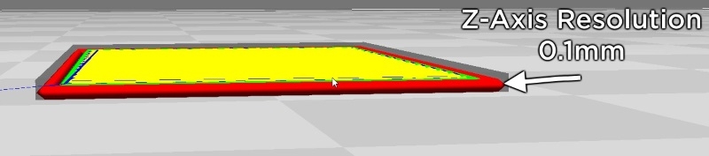
The finest resolution on your printer (above) dictates the size of features that you can print. For the X-Y direction it is your nozzle width, and for the Z-direction, it is the smallest layer height. For example, I love the LulzBot Mini 3D Printer. But, without some serious time, energy and effort, I have to abide by those limitations.
In the Z-direction I don't have much luck with anything less than 0.1mm with standard profiles.
The smallest X-Y features possible are 0.5mm wide.

So keep those values in mind when adding small features to models, they can be an easy gotcha. Also, your printer may have different specs, and therefore resolutions.
Supporting your model
Next up is the general rule of support-less prints. If your model is printing too far away from itself, it will try to extrude into thin air. This is FUSED deposition modelling, so there has to be something to fuse to. The answer to that is support material that can prop it up and help it print.
The support material can be hard to remove. It leaves marks on the model surface once removed, and it can even be impossible to remove in certain cases. The best practice? Design the model, always trying to reduce the amount of support material required. Sure, geometry exists that cant side step the need for support material. Do the best you can and save yourself the time and energy from the removal process.
In spite of the clear hate for support material above, it's not that bad. Especially since there have been huge advances in Dual Extruding recently. The tricky nature of the 'overhang' constraint is starting to become null in void.
I'd say for someone brand new to 3D Model Design, it's best to stick to the general rule of 45 degrees. This rule applies from a horizontal perspective of your model.
"If the model prints away from the previous layer at an angle of greater than 45 degrees the model needs support (see below).

Fillet's and Chamfers
Your 3D Printer's nozzle opening is always some geometry other than a perfect square. That means that printing perfect right angles is not possible. You might've seen cubes printed, but I guarantee they aren't perfect right-angles. It's on these right-angled edges that fillets can be particularly useful.
Fillet - A rounded corner or edge.

By adding a small fillet to the edges of your print, not only do you make it (a lot!) stronger, but you also give the model a nicer aesthetic. See the images below if my written description of that geometry made your eyes roll over.

Chamfer - A sloped corner or edge.
Chamfering an edge is a different method we use to design models. This is invaluable for designing small features into a vertical wall of a model file. To chamfer an edge, add a small feature to a wall and press the bottom side edge of that feature into the model. Try and keep that angle at 45 degrees to see the benefit of a chamfer. See below for a visual representation of what I mean.

These two design methods allow us to make right-angled edges and geometry far more printable!
Printing Holes for Fasteners
To join printed parts with the environment you can print them in place, or, you can join them with fasteners. "Printing a model in place" is when you have many parts joined together, such as living hinges. Usually, you will be designing holes with (and without) threads. Printing threaded holes 'vertically' is best practice. Printing non-threaded holes 'horizontally' works very well.
There are a few reasons for this:
- Threads cannot 3D print 'horizontally' as the resolution of X-Y movements is too large.
- 'Vertical' 3D printing of threaded holes works far better. But, it causes mechanical force from the fasteners, to act at right angles to the layer adhesion force. This is not good for part strength.
- Circular geometry printed on the side of models does not appear circular (see below)
- Printing holes 'vertically' allows fasteners to 'bite' into the walls of the print. Yet, your hole may be completely unsupported on the inside of the model; depending on your infill. Printing holes 'horizontally' guarantees internal support (+1 to strength, yay).

For the strongest joins possible, use a 'horizontal' hole orientation. But, if you need clean, accurate holes in your model, print them 'vertically'. Above, I mentioned thread design and 3D printing, but I haven't dived into that. I'll do that in a future tutorial called 3D Printing Threads!
The above methods and practices will allow you to know a little more when it comes to 3D model design. Every tip has helped me when it comes to designing bits and pieces around the workshop. If you think I've missed a tried and tested design guideline, please let us know! I'd love to hear from the community when it comes to designing practical 3D Printed Parts.

