[Update – Until there is correct compatibility of OPEN-CV with the new Raspberry Pi ‘Bullseye’ OS I highly recommend at this stage flashing and using the previous Raspberry Pi ‘Buster’ OS onto your Micro-SD for use with this guide – Official 'Buster' Image Download Link Here]
Have you ever wanted to get your Raspberry Pi 4 Model B to actively search, identify and record the data of any QR code? Or use QR codes to control GPIO pins? Then you have come to the right place.
QR (Quick Response) Codes are absolutely everywhere in our modern world and for great reason. Sharing a lot of similarities to barcodes, but instead of a laser, a camera is used to identify spaces between square markings. Being able to encode data represented by black and white squares is incredibly useful and with machine learning, it has never been easier to decode their (indecipherable by human eyes) secrets. Then depending on your software you can then display the output live, send that information to be processed, allow it to direct you to a website, or do anything that you desire.
So let's use our Raspberry Pi to view a whole bunch of QR codes in real-time, display their data live, and then capture the information in a text/excel compatible file. Then we can go a step further and use certain QR codes to control the GPIO pins of our Raspberry Pi Single Board Computer. The contents of this guide are as follows.
- What You Need
- Hardware Set-Up
- Software Set-Up
- QR Identification and Decode Code and Demonstration
- Output CSV Data from QR Code and Demonstration
- Where to Now (GPIO Control)
- Downloads
QR codes can encode a variety of data types, including numbers, characters, and binary, which can allow for many creative uses. Advertisers often encode URLs with them to redirect the user to their website. Companies place important product information in a QR code, such as a serial number, and attach it to a component. And in Australia, they are regularly used when entering businesses. There are lots of standards and types of QR codes but this system will work with all common types. Any custom QR codes created by this generator will be read by our Raspberry Pi system.
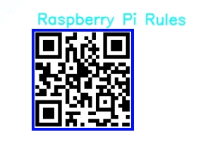
This will use Open-CV which is a huge resource that helps solve real-time computer vision and image processing problems. This will be the fourth foray into the Open-CV landscape with Raspberry Pi and Facial Recognition being the first, Object and Animal Recognition with Raspberry Pi being the second, Speed Camera With Raspberry Pi being the third. Other computer vision guides I have created are Face and Movement Tracking with a Pan-Tilt System and Pose Estimation/Face Masking with Raspberry Pi. See below for an image from a live stream of a Raspberry Pi camera as it sees a QR Code, draws a blue box around it, successfully reads the data, and writes it above the QR square.
If you happen to be holding a Raspberry Pi single-board computer and not quite sure what it is? Then check out this guide Raspberry Pi Generations to identify it. As always if you have got any questions, queries, or things you'd like to see added please let us know your thoughts!
What You Need

- Raspberry Pi 4 Model B (Having the extra computing power that this Pi provides is very helpful for this task)
- Raspberry Pi Official Camera Module V2 (You can also use the Raspberry Pi High-Quality Camera and a Lens)
- Micro SD Card
- Power Supply
- Monitor
- HDMI Cord
- Mouse and Keyboard
Hardware Set-Up
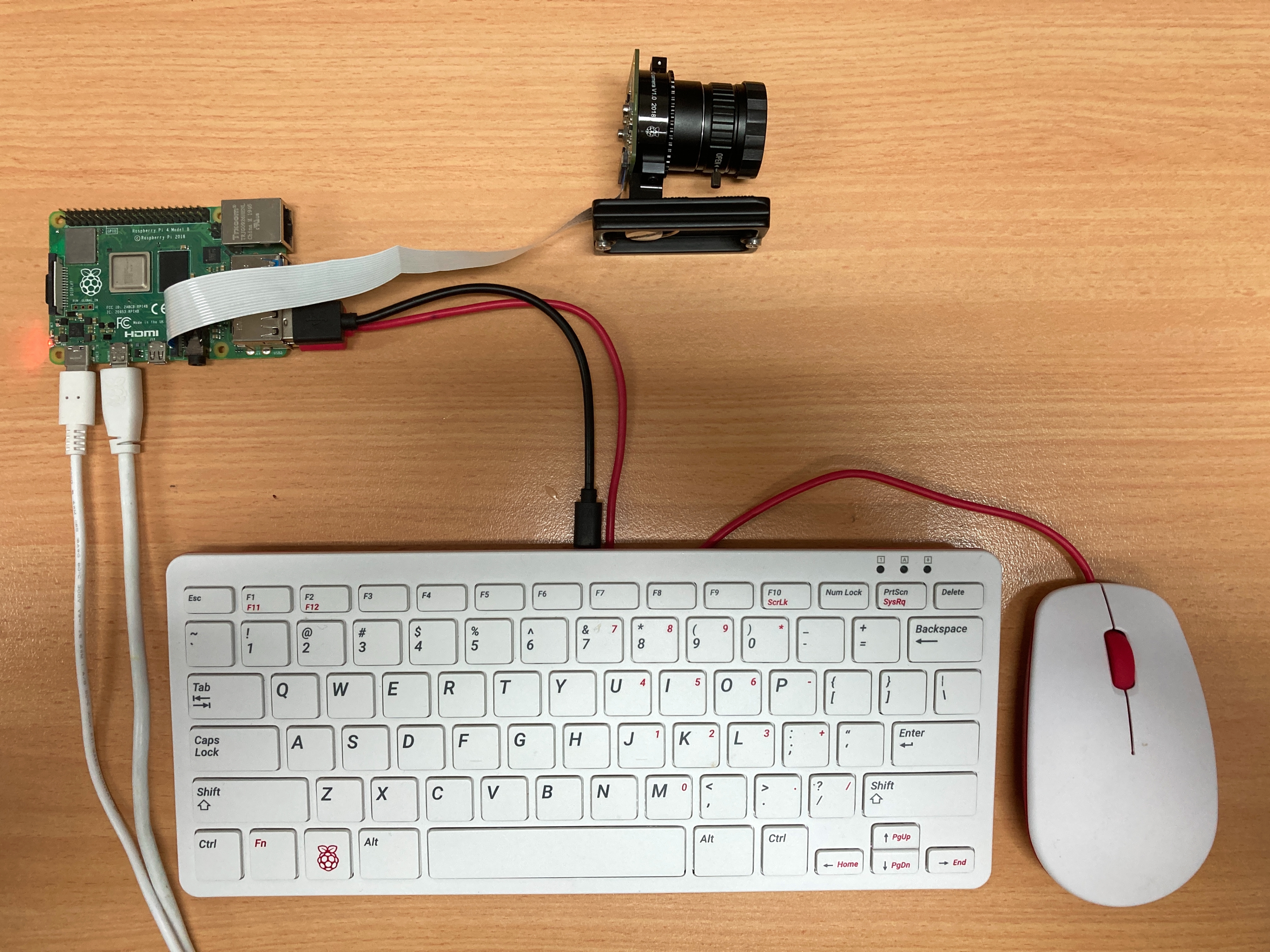
The fast way to get up and running with object recognition on the Raspberry Pi is to do the following. Flash a micro-SD card with a fresh version of Raspberry Pi 'Buster' OS. Link on how to flash micro-SD with Raspberry Pi 'Buster' OS found here. With the Micro-SD Card flashed you can insert it into your Raspberry Pi. Then make sure to have the Raspberry Pi connected to a Monitor, have peripheries (keyboard and mouse) and a Pi Camera is installed in the correct slot with the ribbon cable facing the right way. With that plug in a USB-C cable to provide power to the system. See below for an image of all the hardware and plugs connected up.
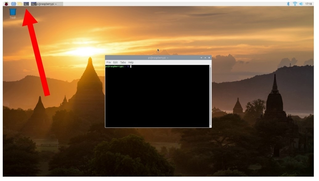
As soon as you provide power to the Pi through the USB-C plug it will start booting the Raspberry Pi. Then once the booting sequence is over you will be welcome with the Raspberry Pi OS and the familiar Angkor Wat background. This you can see in the image below as well as an arrow pointing to the internet connection button. Connect the system to the internet using that WIFI symbol on the top right.
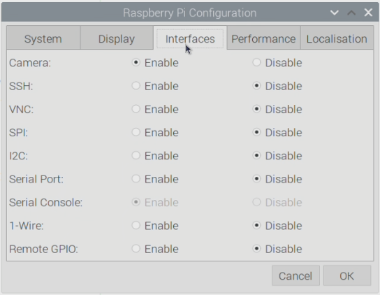
Then open up the Raspberry Pi Configuration menu (found using the top left Menu button, the one with a Raspberry Icon, and scrolling over Preferences). In this menu enable the Camera found under the Interfaces tab, see the image below for the setting location. After enabling reset your Raspberry Pi.
Software Set-Up
For this to work, we will incorporate the incredible Open-CV software and code for our QR system. Open-CV is a huge resource that helps solve real-time computer vision and image processing problems. To install it we will type and enter the following lines into the Raspberry Pi Terminal. Open up a new terminal using the black button on the top left of the screen. Below you can see what it looks like when you open this in Raspberry PI 'Buster' OS and there is a big arrow pointing to the icon which was clicked with the mouse.
In the Terminal, we are going to type and enter the following below lines. If prompted type | Y | and press enter to continue the install process. Installing each of the packages should take less than 4 minutes. See further below an image of the second line being downloaded. Most lines here start with | sudo | (which means each line will run with admin privileges) and is being used here to update and install all the current packages to the current setup.
sudo apt-get update
sudo apt-get install python3-opencv
sudo apt-get install libqt4-test python3-sip python3-pyqt5 libqtgui4 libjasper-dev libatlas-base-dev -y
pip3 install opencv-contrib-python==4.1.0.25
sudo modprobe bcm2835-v4l2
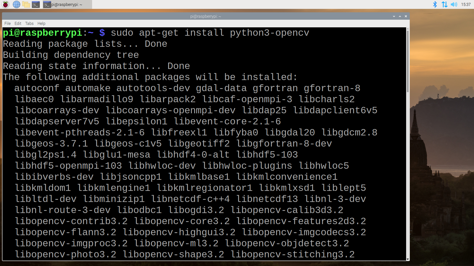
That is all the packages you will need for this application to work. Run a quick reboot to lock in all these changes.
QR Identification and Decode Code and Demonstration
In this section we will use our Raspberry Pi to analyse a live stream (coming from the Raspberry Pi Camera) for QR Codes. When it finds one it will draw a blue box around it and then will write the decoded QR data in plain text above the box. The live stream (which we will be able to see running on the Raspberry Pi) will be actively searching for QR codes and when it finds a QR code it will look a lot like the below screen capture.

Below is the code to do just this thoroughly commented. No extra packages need to be downloaded to run this code successfully. All you need to do is open it up (or copy, paste, and save it) in Thonny IDE (or any Python interpreter that you would like). Then with it open, run that code pressing the Green Run Button. You can also download this code at the bottom of the page.
#most importantly for this code to run is to import OpenCV which we do in the below line
import cv2

# set up camera object called Cap which we will use to find OpenCV
cap = cv2.VideoCapture(0)

# QR code detection Method
detector = cv2.QRCodeDetector()

#This creates an Infinite loop to keep your camera searching for data at all times
while True:

    # Below is the method to get a image of the QR code
    _, img = cap.read()

    # Below is the method to read the QR code by detetecting the bounding box coords and decoding the hidden QR data
    data, bbox, _ = detector.detectAndDecode(img)

    # This is how we get that Blue Box around our Data. This will draw one, and then Write the Data along with the top (Alter the numbers here to change the colour and thickness of the text)
    if(bbox is not None):
        for i in range(len(bbox)):
            cv2.line(img, tuple(bbox[i][0]), tuple(bbox[(i 1) % len(bbox)][0]), color=(255,
                     0, 0), thickness=2)
        cv2.putText(img, data, (int(bbox[0][0][0]), int(bbox[0][0][1]) - 10), cv2.FONT_HERSHEY_SIMPLEX,
                    1, (255, 250, 120), 2)

        #Below prints the found data to the below terminal (This we can easily expand on to capture the data to an Excel Sheet)
        #You can also add content to before the pass. Say the system reads red it'll activate a Red LED and the same for Green.
        if data:
            print("data found: ", data)
            if data == 'red':
                pass
            if data == 'green':
                pass


    # Below will display the live camera feed to the Desktop on Raspberry Pi OS preview
    cv2.imshow("code detector", img)

    #At any point if you want to stop the Code all you need to do is press 'q' on your keyboard
    if(cv2.waitKey(1) == ord("q")):
        break

# When the code is stopped the below closes all the applications/windows that the above has created
cap.release()
cv2.destroyAllWindows()
As soon as you run the code it will actively search for QR codes. When it finds a QR code and captures the data it will write it into the Shell, this will be useful in the next step to record the information in CSV (comma-separated value) format. It will also draw a box around it on the live stream and write the data above the square. See the image below for a screencap of what you should see on your Raspberry Pi when it captures information from a QR code, note the Green Run Button.
Output CSV Data from QR Code and Demonstration
This code will do exactly what was happening before except this time it will take that recorded information and store it in a text file format that can easily be read by excel. The format used will be CSV and each QR code will have the data, date and a time-stamp recorded into a text file. To capture this information with the code below you will need a text file named | Database.csv | saved in the same directory (in my case the desktop) as the code. The code used to do this is below. You can find it called | QR-Simple-Code-With-CSV.py | and a blank text file named correctly at the bottom of the page in the download section.
Code is similar to before but note the Adding Time section and the CSV Write control

#most importantly for this code to run is to import OpenCV
import cv2
import csv

#adding time and date stuff and rearranging it
from datetime import date, datetime

today = date.today()
date = today.strftime("%d-%b-%Y")

now = datetime.now()
timeRN = now.strftime("%H:%M:%S")


# set up camera object called Cap which we will use to find OpenCV
cap = cv2.VideoCapture(0)

# QR code detection Method
detector = cv2.QRCodeDetector()

#This creates an Infinite loop to keep your camera searching for data at all times
while True:

    # Below is the method to get a image of the QR code
    _, img = cap.read()

    # Below is the method to read the QR code by detetecting the bounding box coords and decoding the hidden QR data
    data, bbox, _ = detector.detectAndDecode(img)

    # This is how we get that Blue Box around our Data. This will draw one, and then Write the Data along with the top
    if(bbox is not None):
        for i in range(len(bbox)):
            cv2.line(img, tuple(bbox[i][0]), tuple(bbox[(i 1) % len(bbox)][0]), color=(255,
                     0, 0), thickness=2)
        cv2.putText(img, data, (int(bbox[0][0][0]), int(bbox[0][0][1]) - 10), cv2.FONT_HERSHEY_SIMPLEX,
                    1, (255, 250, 120), 2)

        #Below prints the found data to the below terminal (This we can easily expand on to capture the data to an Excel Sheet)
        #You can also add content to before the pass. Say the system reads red it'll activate a Red LED and the same for Green.
        if data:
            print("data found: ", data, date, timeRN)


       #**** This location is where we are adding the ability for the code to capture the Data and write it to a Text file
       #For this here we are writing the Information to Database.csv File located in the same directory (the desktop) as this code.
            with open('Database.csv', mode='a') as csvfile:

                csvfileWriter = csv.writer(csvfile, delimiter=',', quotechar='"', quoting=csv.QUOTE_ALL)
                csvfileWriter.writerow([data, date, timeRN])


            if data == 'red':
                pass
            if data == 'green':
                pass


    # Below will display the live camera feed to the Desktop on Raspberry Pi OS preview
    cv2.imshow("code detector", img)

    #At any point if you want to stop the Code all you need to do is press 'q' on your keyboard
    if(cv2.waitKey(1) == ord("q")):
        break

# When the code is stopped the below closes all the applications/windows that the above has created
cap.release()
cv2.destroyAllWindows()
See a screencap of exactly what will happen when you scan QRs with the above code running.
Where to Now (GPIO Control)
The natural next step would be to use QR Codes to activate the GPIO pins on the Raspberry Pi. For example, if a QR Code had embedded into the data | Red | when the Raspberry Pi identifies that QR code it will light up a red LED. This we will do here but understand that this LED is just a placeholder for anything! GPIO pins are the doorway to controlling almost an endless amount of sensors, motors, actuators, hardware. It is up to your curiosity to decide what you will do with it. Simply, as you can see in the below images, I will add the following lines to the top section of the code and lower down. You can also simply download this completed code at the bottom of this page.
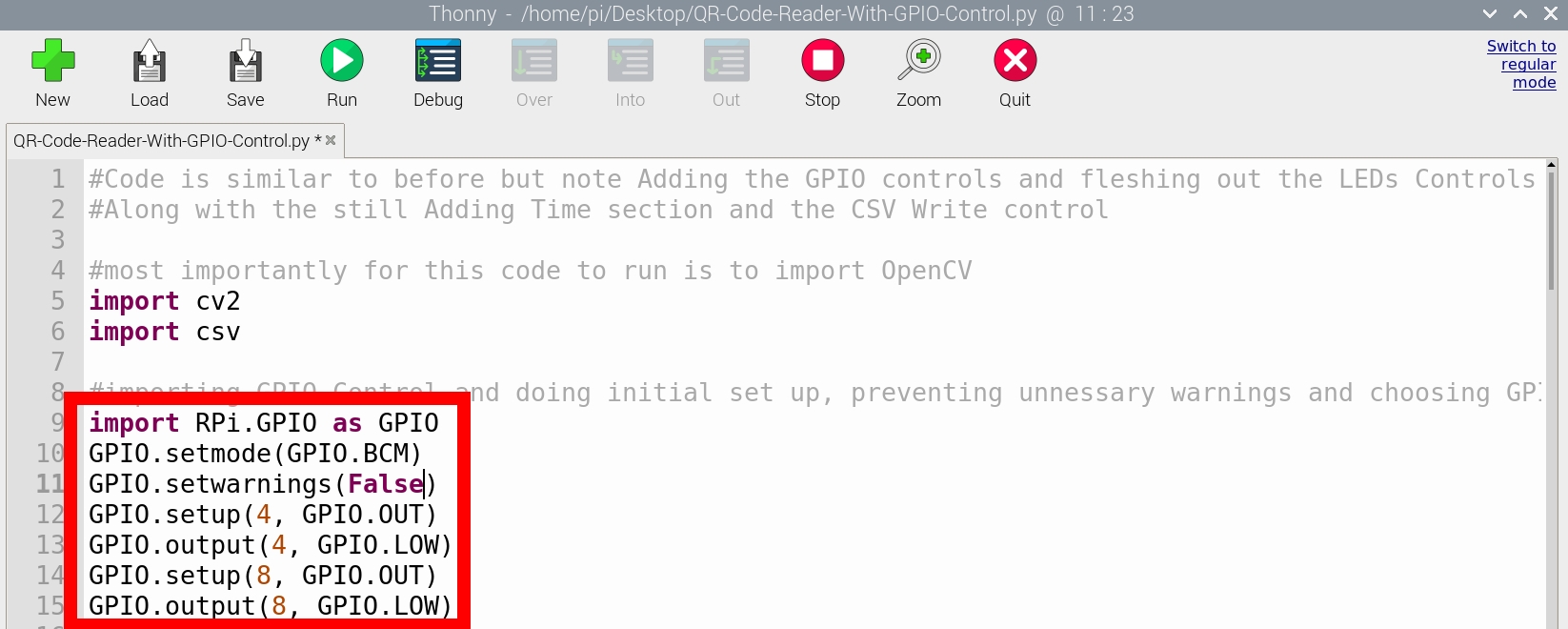
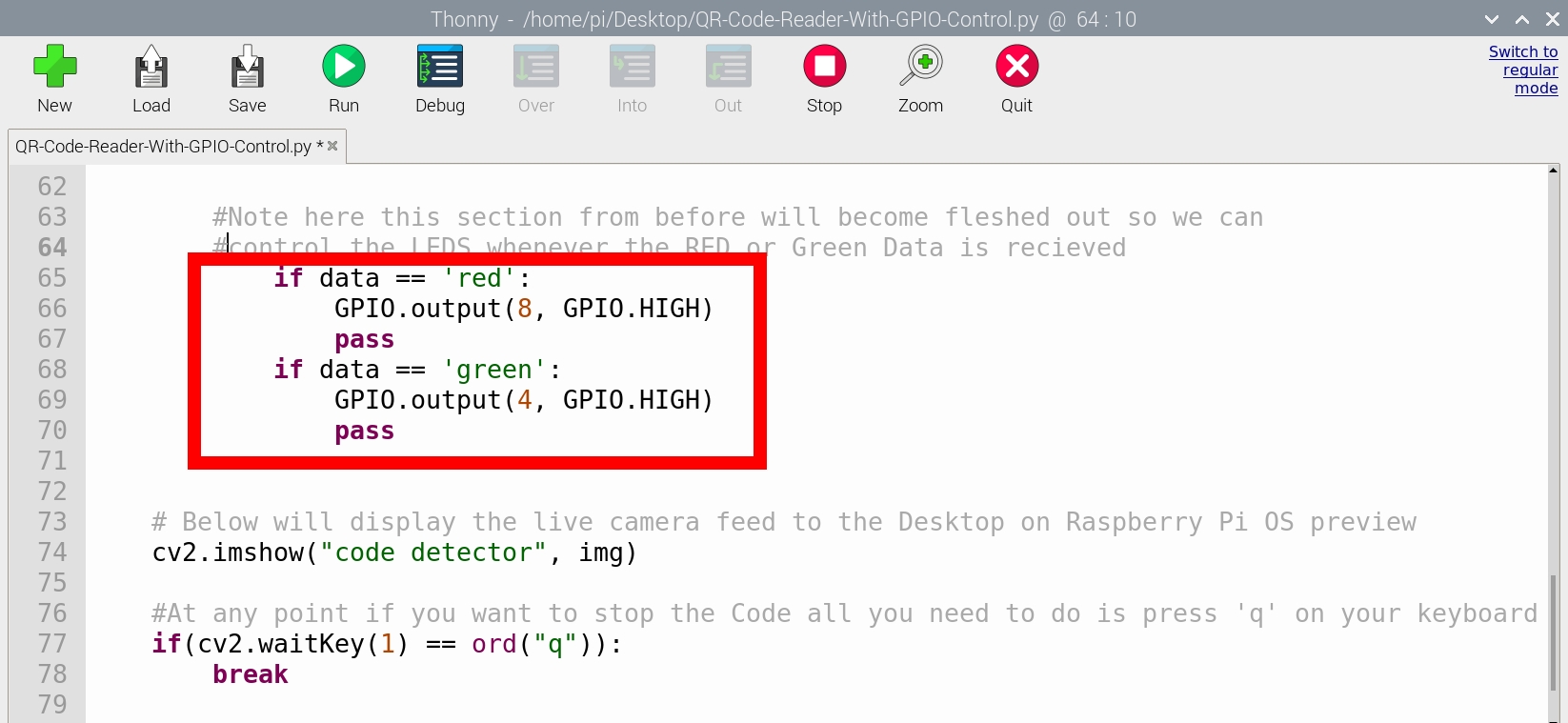
Now wire up two LEDs (with matching resistors in series for both) and attach them to Ground Pins and the GPIO Pin 8 and GPIO Pin 4 respectively of the Raspberry Pi. Then whenever you run the code and show it QR data that has | Red | or | Green | encoded to it they are going to light right up! See the image below for this setup running and a very clear top-down view of the breadboard used.

A great guide to clarify at a grassroots level the code and why certain connections are made can be found in Chapter 2 of the Raspberry Pi Workshop. GPIO (General Purpose Input and Output) is the interface that allows your Raspberry Pi to connect to the outside world. This can be any manner of control and you are only limited by your imagination.
Downloads
Below is all the code you need to get up and running with these examples above. They have been fully commented so you can easily understand and alter them to do exactly what you want for your purposes.

